
Abstract
The influence of difference in thickness, material properties and the weld zone on deep drawing and stretch forming behavior of tailor welded blanks is a critical laboratory scale study before implementation in car body design. Mostly, various low-carbon steel sheets are used for fabrication of tailor welded blanks due to their excellent weldability and formability, and these steel sheets have high normal and planar anisotropy from preprocessing stage due to large deformation cold rolling. In this study, two different tailor welded blanks and one laser welded blank of similar material combination were fabricated by laser welding of interstitial-free, interstitial-free high-strength and high-strength low-alloy steels. Transverse tensile testing of the laser welded blanks of similar material combination (interstitial free–interstitial free) and two tailor welded blank specimens (interstitial free–interstitial free high strength and interstitial free–high strength low alloy) were conducted to evaluate the weld quality in terms of strength and failure location. The effect of anisotropy on formability of tailor welded blanks was investigated in terms of cup depth and fracture location in cylindrical deep drawing process. Finite element simulations of the deep drawing process were conducted using the commercial available nonlinear solver, RADIOSS. It was observed that the Lankford anisotropy parameter, R-value, influences the thickness distribution, weldline movement and failure location in tailor welded blanks.
Introduction
The stringent emission norms and economic concerns impel the automotive manufacturing industries to push the limits in design of vehicles for weight and cost reduction while maintaining or improving structural integrity and crashworthiness. Weight savings have a remarkable influence on vehicle’s efficiency, and researchers have showed that 1% reduction in vehicle weight can result in 0.6%–1% reduction in fuel consumption. 1 In this regard, the last decade has seen several research work targeted to improve utilized manufacturing processes and materials in automotive body stampings. Among these various research works aiming at fulfilling the above conflicting demands, tailor welded blanks (TWBs) have emerged as the most widely accepted technology in the automotive body manufacturing industries. TWBs consist of two or more sheet metal pieces differing in gauge, strength and/or surface coatings that are mostly laser welded together prior to sheet forming. 2 These multi-material engineered blanks with an intention of taking the advantages of localized material properties wherever required are subsequently stamped into three-dimensional automotive components. Laser welding is commonly used in various TWB fabrication as it provides narrow fusion zone (FZ) and heat-affected zone (HAZ) with deep penetration. 3 Some potential applications of TWBs are vehicle body structures including body side panels, pillars, floor panel, door inner panel, wheel house panel, frame rail and so on. 4 The various advantages of application of TWBs in manufacturing these components are as follows: weight saving, part count reduction, stiffness/weight ratio improvement, crashworthiness and overall manufacturing cost reduction. 5
The formability of TWBs is found to be significantly affected by the weld and HAZ properties 6 and the location and orientation of the weldline. 7 It was observed that nonuniform deformation in the thicker/stronger and thinner/weaker sides leads to the movement of weldline in the sheet formed part. 8 Padmanabhan et al. 9 had conducted the finite element (FE) simulation of deep drawing of TWB consisting of mild steel and dual-phase steel. A weldline displacement toward the dual-phase steel, which was the stronger material in the cup section, was observed. The application of adaptive clamping pins at the weldline, 10 segmental blank holders with differential holding force 11 and draw-beads at the thinner blank side 12 is successfully tried by various researchers to restrict the weldline movement, thereby improving the formability of TWBs.
The formability of TWBs has been studied by many researchers both experimentally and numerically using standard formability tests, such as free bending, stretch forming and limit dome height test. However, most of the previous studies were confined to the effect of thickness mismatch on formability of TWBs. It is observed that very little information is available on formability characterization of TWBs made of different materials experimentally and especially the effect of material property mismatch under complex stress–strain states such as in deep drawing process. Hence, the present investigation is focused on the evaluation of forming behavior of TWBs fabricated by laser welding two different materials, and the followings are the main objectives:
to successfully fabricate laser welded blanks (LWBs) of similar material combinations of interstitial-free (IF) steel sheets and two TWBs (interstitial free-high strength low alloy(IF-HSLA) and interstitial free-interstitial free high strength) using 2-kW fiber laser setup;
to compare the formability of parent metals and the welded blanks in terms of cup depth in a laboratory scale cylindrical deep drawing setup;
to develop an FE model of deep drawing of the TWB incorporating the difference in material properties to study the influence of anisotropy properties on deep drawing behavior in terms of cup depth, failure location, thickness distribution and weldline movement.
Materials and methods
The materials used in this work were IF and HSLA steels both with a nominal thickness of 1.0 mm and IFHS with a nominal thickness of 0.7 mm. The chemical compositions of these steel sheets are mentioned in Table 1. These are particularly low-carbon steel sheets that have been developed for stamping automotive parts for structural and exterior applications. All these steels showed equiaxed ferrite grains. However, HSLA steel consists of ferritic microstructure in which the submicron second-phase precipitates are revealed at the grain boundaries. 13
Chemical composition of the sheet materials used in this study.
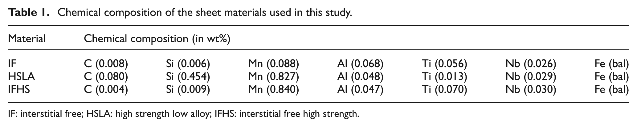
IF: interstitial free; HSLA: high strength low alloy; IFHS: interstitial free high strength.
Preparation of TWBs
In this study, LWB of IF-IF combination was just tried to understand the effect of fiber laser welding on deep drawing. TWBs were prepared with combination of IF-HSLA and IF-IFHS. First combination was supposed to enlighten the predominant influence of strength or anisotropy on deep drawing. Second combination was performed to know the influence of thickness over strength or vice versa. First, the samples from the parent metals were cut in required size and orientation using the wire cut electric discharge machining (EDM) machine. The cut steel samples were polished smoothly and cleaned using acetone to remove the oxides at the faying surface to be welded in butt configuration. The laser welding head of the 2-kW fiber laser setup was kept at a focal distance of 346 mm in the z-axis. After a series of trials, all the weldings of IF-IF LWBs and IF-HSLA TWBs were carried out with a laser power of 1.8 kW and at a scan speed of 6000 mm/min successfully. However, the IF-IFHS TWBs of different thickness combination were fabricated with laser power of 1.6 kW at the scan speed mentioned earlier. The argon gas at a flow rate of 20 standard liter per minute (SLPM) was used as shrouding gas to prevent oxidation of the weld pool during the laser welding. All the LWBs and TWBs were obtained with weldline oriented perpendicular to the rolling direction (RD). The similar material combination LWBs (IF-IF), different material combination TWBs (IF-HSLA) and thickness combination TWBs (IF-IFHS) were fabricated successfully with complete weld penetration. The weld zone section of IF-HSLA and IF-IFHS TWBs is shown in Figure 1(a) and (b), respectively, for reference. It was observed from microhardness profile across the weld section that very narrow weld zones were obtained with the weld widths ranging from 0.5 to 0.7 mm. The hardness was found to increase in the FZ and HAZs for all the welded samples as compared to that of the respective base metals. In LWBs, the FZ hardness increased by 75%–100% in the HSLA-HSLA combination having the maximum value of 349 VHN. Similarly, FZ hardness increased by 245% in the IF-HSLA TWB with a peak value of 352 VHN (Figure 1(c)). The detailed metallographic and microhardness studies of these welded samples were presented elsewhere. 14
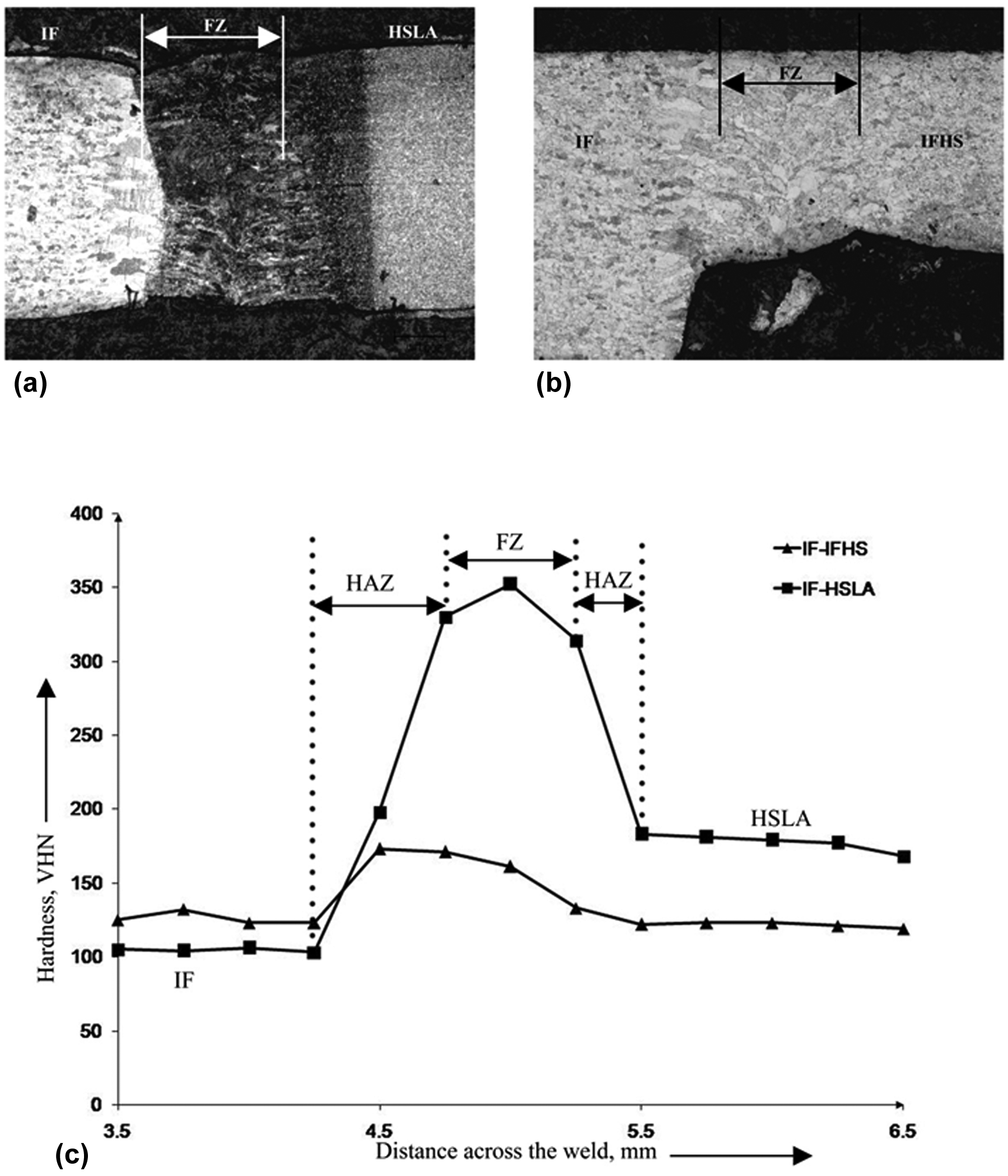
Macrostructure and microhardness observed in the cross-sectional TWBs: (a) IF-HSLA weld profile, (b) IF-IFHS weld profile and (c) microhardness profile across the TWBs.
Uniaxial tensile testing
The room temperature uniaxial tensile testing was conducted on the ASTM E8M standard specimens using Instron 8088 uniaxial tensile testing machine at a crosshead speed of 4 mm/min. The parent metal specimens were tested along the three directions, where the tensile axis was parallel (0°), diagonal (45°) and normal (90°) to the RD of the sheet. The standard tensile properties, 0.2% yield strength (YS), ultimate tensile strength (UTS), percentage elongation, strain hardening coefficient (n-value), strength coefficient (K-value) and Lankford anisotropy parameters (R-value), were determined. 14 Transverse tensile tests of the subsized welded samples were conducted to characterize the weld quality and fracture location.
Deep drawing experiment
The formability of both parent metals and welded blanks was evaluated by carrying out laboratory scale cylindrical deep drawing operation. Circular blanks of 80 mm diameter were blanked and then deformed by a cylindrical punch mounted on a 25-ton single-action hydraulic press attached with a load indicator. The tooling used for the deep drawing operation includes the following: a die of 39.0 mm diameter with corner radius of 8.0 mm, a cylindrical punch of 36.0 mm diameter with a corner radius of 6.0 mm and a blank holder plate. Figure 2(a) shows the schematic representation of the deep drawing setup. Adequate blank holding force was applied using a torque wrench to allow flange material draw into the die cavity while avoiding wrinkles as shown in Figure 2(b). All welded blanks were aligned with the weldline passing the center of the die cavity and weld root pointing toward the punch face while deep drawing of LWBs and TWBs. The parent metal blanks and welded blanks were deep drawn in dry condition (without lubrication) till localized necking was observed. It was observed that the drawing load gradually increased from the start of deep drawing, and it started to fall at the onset of localized thinning, which led to subsequent failure. This phenomenon was observed from deflection of the load indicator. After exploiting some trial experiments, it was possible to stop the deep drawing experiment during the onset of thinning/failure, and the deep drawing test was stopped within a fall of load of 0.3 ton from the maximum load.
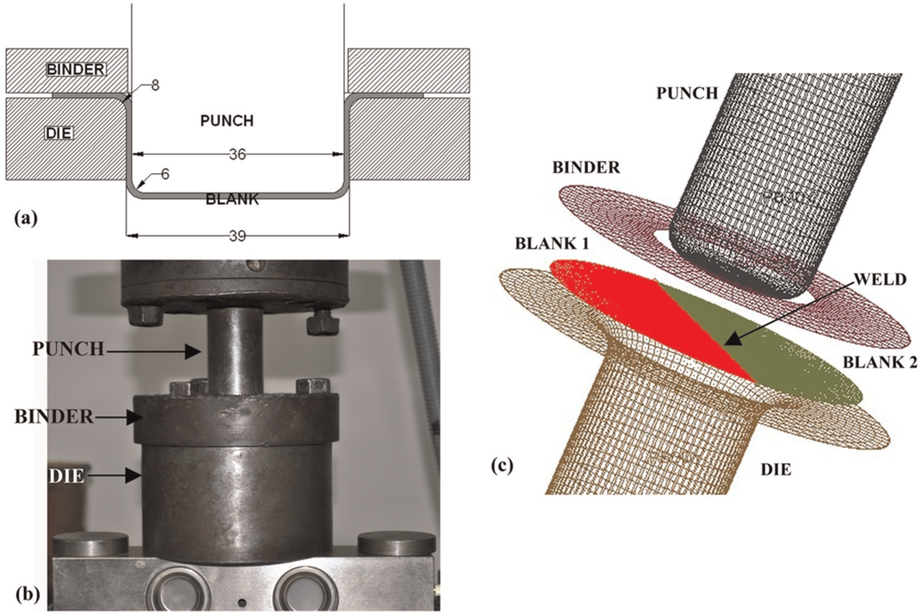
Tooling used in deep drawing: (a) schematic diagram of the tools (with dimensions in millimeters), (b) experimental test setup and (c) finite element modeling of tooling and TWB.
FE simulation
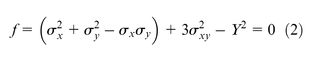
Numerical simulation of the deep drawing process was performed using commercially available FE-code, RADIOSS nonlinear solver. All the tooling surfaces were modeled using four-node shell elements (Figure 2(c)). The blanks were modeled using four-noded quadrilateral Belytschko–Tsay shells. As deformation of blank is of the main concern, tooling was modeled with shell element and considered to be rigid experiencing no deformation. Die was fixed; however, both punch and binder were allowed to move only in the z-direction, which was coinciding with the punch axis. Adequate blank holding force (binder force) was applied to avoid flange wrinkling. In TWBs, the weld zone was treated as a weldline at the center of the blank. The deformable blank was modeled using both von Mises and Hill’s quadratic yield criteria. The von Mises yield criterion is one of the most widely accepted yield functions for isotropic materials. It is expressed in terms of general stress state as 15
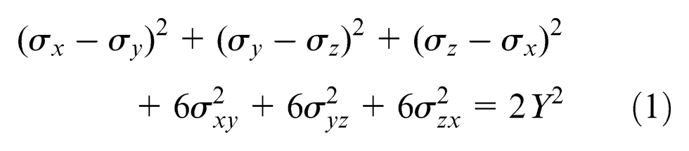
where σx, σy and σz are the normal stresses in an arbitrary set of orthogonal directions with σxy, σzx and σyz representing the corresponding shear stresses and
The Hill’s 48 yield criterion is most commonly used for anisotropic sheet materials. Woodthrope and Pearce have reported anomalous yield behavior in sheet metal having R < 1 (especially aluminum sheet) using Hill’s 48 criterion.16,17 However, all the steel sheet materials used in this study have R > 1, and hence, Hill’s 48 yield criterion is suitable in the present FE modeling. It is expressed by a quadratic function in plane stress condition as 18
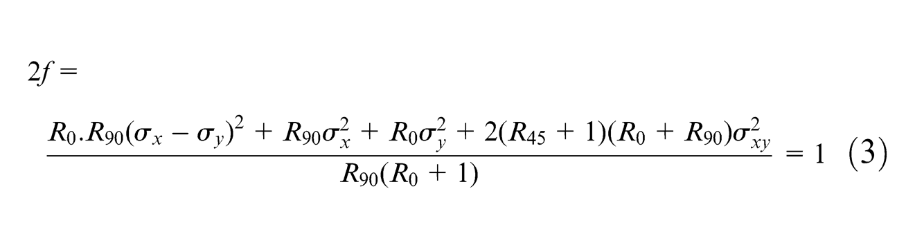
where R0, R45 and R90 are Lankford anisotropy parameters along the three tensile axes.
The material hardening behavior was described using Hollomon’s power hardening law

where σeq is the equivalent stress and εeq is the equivalent strain. The isotropic hardening model was considered due to following reasons: (1) Bauschinger effect is neglected during sheet deformation and (2) the change in strain hardening exponent has a negligible influence on deep drawing behavior of sheet metal. 19
Failures of sheet metal occur by strong local thinning/necking after diffuse necking. The deformation is confined to the localized necking region without further contraction of width of specimen, and this region leads to tearing of sheet metal on further deformation. This localized necking is a visible indication that the sheet metal has been worked beyond its prevailing limit. Whether or not a particular sheet metal can be formed without failure depends on many factors such as material properties, surface conditions, blank size and shape, lubrication, press speed, blank holder pressure, punch and die design. Limiting strain values at the surface of the sheet material elements under localized necking can be defined as the forming limit strains, while a forming limit diagram (FLD) can be constructed with combinations of various forming limit strains obtained from different strain path from uniaxial tension, plane strain tension and biaxial tension tests.20,21 The FLDs were used as a damage model to identify the time step at which there was first appearance of localized necking on the drawn cup, which limits the formability of the sheet metal. Fracture location, weldline movement and the thickness distribution of the TWB were predicted in the simulation.
Results and discussion
Uniaxial tensile testing of welded sheets
The standard tensile properties of IF, IFHS and HSLA sheet metals used in this study are given in Table 2. Figure 3 shows the comparison of engineering stress–engineering strain response of the parent metals and all welded blanks. IF-IF LWB specimen was found to have UTS similar to that of the parent IF specimen indicating negligible influence of weld zone. In IF-HSLA TWB, deformation and failure occurred in the IF side during tensile testing as HSLA has higher YS compared to the UTS of IF. So, tensile strength of IF-HSLA was found to be less than that of HSLA parent material and comparable with IF parent metal. Figure 4 shows the failure locations observed in all the transverse tensile tested specimens. Failure occurred at the base metal in all transverse LWBs, ensuring good quality of welds with complete penetration without porosity and mismatch. The necking and fracture occurred at a distance of 13.5 mm from the weld center in the IF-IF LWBs. Hence, the fracture location and the stress–strain response of the LWBs indicated that there was no major reduction in ductility due to the presence of the narrow and hard weld. In IF-HSLA TWBs (having strength ratio, defined as
Mechanical properties of the sheet metals.
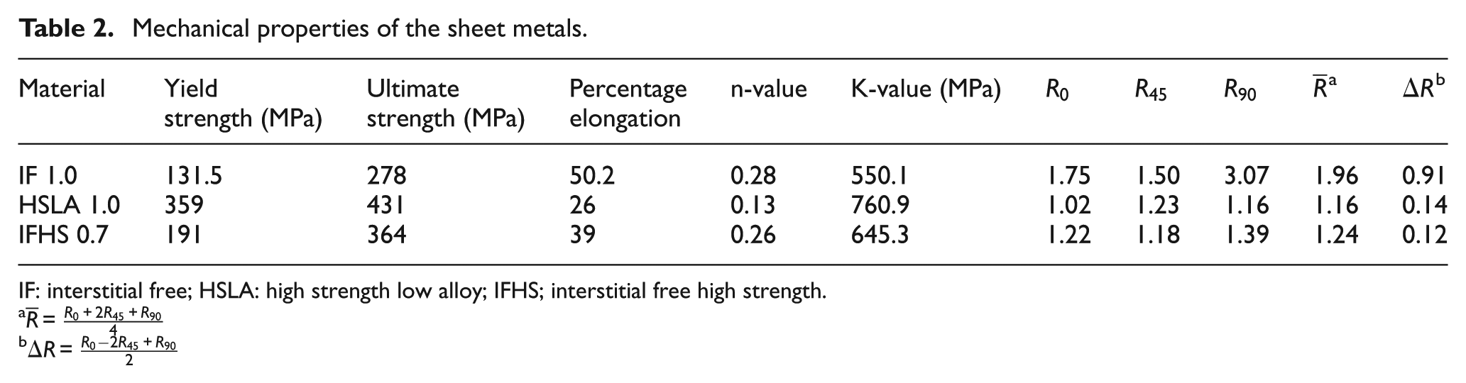
IF: interstitial free; HSLA: high strength low alloy; IFHS; interstitial free high strength.
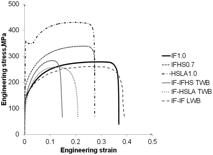
Engineering stress–engineering strain curves of parent metals, IF-IF similar welded specimen and the TWBs.
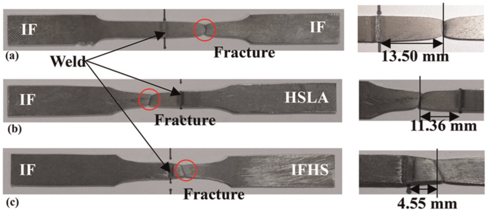
Transverse tensile tested specimens with fracture location from weld in millimeters: (a) IF-IF LWB, (b) IF-HSLA TWB and (c) IF-IFHS TWB.
Influence of anisotropy on drawability of welded blanks
The depth of the cylindrical drawn cups till necking/failure was measured using a height gauge of least count of 0.01 mm. All the deep drawn cups with their measured height are shown in Figure 5. It was observed that deeper cups were obtained from IF steel with a cup depth of 22.25 mm compared to those from HSLA and IFHS steels. The cup depth is the measure of formability (also referred as drawability) of steel sheets in deep drawing process. The higher drawability of IF steel was due to its higher average anisotropy parameter, R-value, which leads to higher resistance to thinning during deep drawing. A reduction in cup depth of about 5%–7% was observed for the LWBs compared to the respective parent metals that showed the negligible effect of weld zone on the drawability of the selected steel sheets. The cup depth for the IF-HSLA TWB (14.20 mm) was found to be higher than that of the HSLA parent metal but lower than that of IF parent metal. Hence, the drawability of TWBs depends on the material combination. Moreover, the localized necking and subsequent failure were observed to be initiating at the cup corner of the stronger HSLA steel side (Figure 5(c)), which was contrary to the observations by previous researchers. 9 This shows the effect of anisotropy parameter, R-values, on the deep drawing behavior of IF-HSLA TWB. Higher R-values of IF steel resist thinning during deep drawing, which results in necking on the stronger HSLA side having a lower R-value, and this leads to 37% reduction in the cup height compared to parent IF steel sheet. In the IF-IFHS TWB with thickness ratio of 1.43, the cup depth was found to be 19.45 mm, which was more than the cup depth of the thinner parent metal IFHS (18.25 mm) but lower than the thicker counterpart IF (22.5 mm). In this TWB, necking was observed in the thinner IFHS side as shown in Figure 5(d).
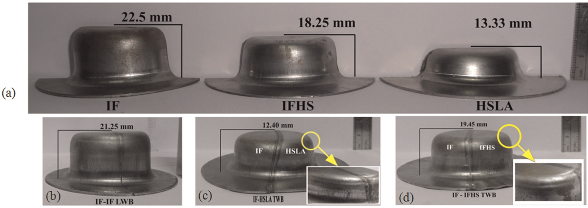
Deep drawn cups with cup depth in millimeters: (a) parent metal cups of IF, IFHS and HSLA; (b) IF-IF LWB cup; (c) IF-HSLA TWB cup and (d) IF-IFHS TWB cup.
The influence of anisotropy on deep drawing of TWBs was further studied through FE simulations incorporating two different yield criteria: (1) von Mises yield criterion that considered the blanks as isotropic and (2) Hill’s yield criterion that incorporated the sheet anisotropy effects. Figure 6(a) shows the fracture locations predicted in the IF-HSLA TWB deep drawn cups by FE simulations. The FE simulation incorporating von Mises yield criterion predicted fracture at the weaker IF side propagating parallel to the weldline. This predicted fracture location by incorporating von Mises criterion defers from the actual experimental results. However, incorporation of Hill’s yield criterion that accounted for the anisotropy parameters predicted the fracture at the cup corner in the stronger HSLA steel side having a lower R-value as observed in the deep drawing experiment. Hence, effect of anisotropy on deep drawing is significant, and it cannot be neglected in the FE model. Figure 6(b) shows the FE simulation results for the uniaxial tensile testing of the IF-HSLA TWB, which matches with the experimental observation. In this case, both the yield criteria predicted fracture to take place in the weaker IF steel side indicating the negligible influence of R-values on the uniaxial tensile straining of TWBs.
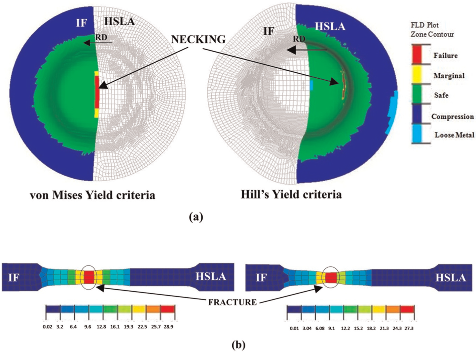
FE prediction of failure location by incorporating von Mises and Hill’s yield criteria: (a) deep drawn cup and (b) uniaxial tensile specimen.
Thickness distribution in the drawn cup
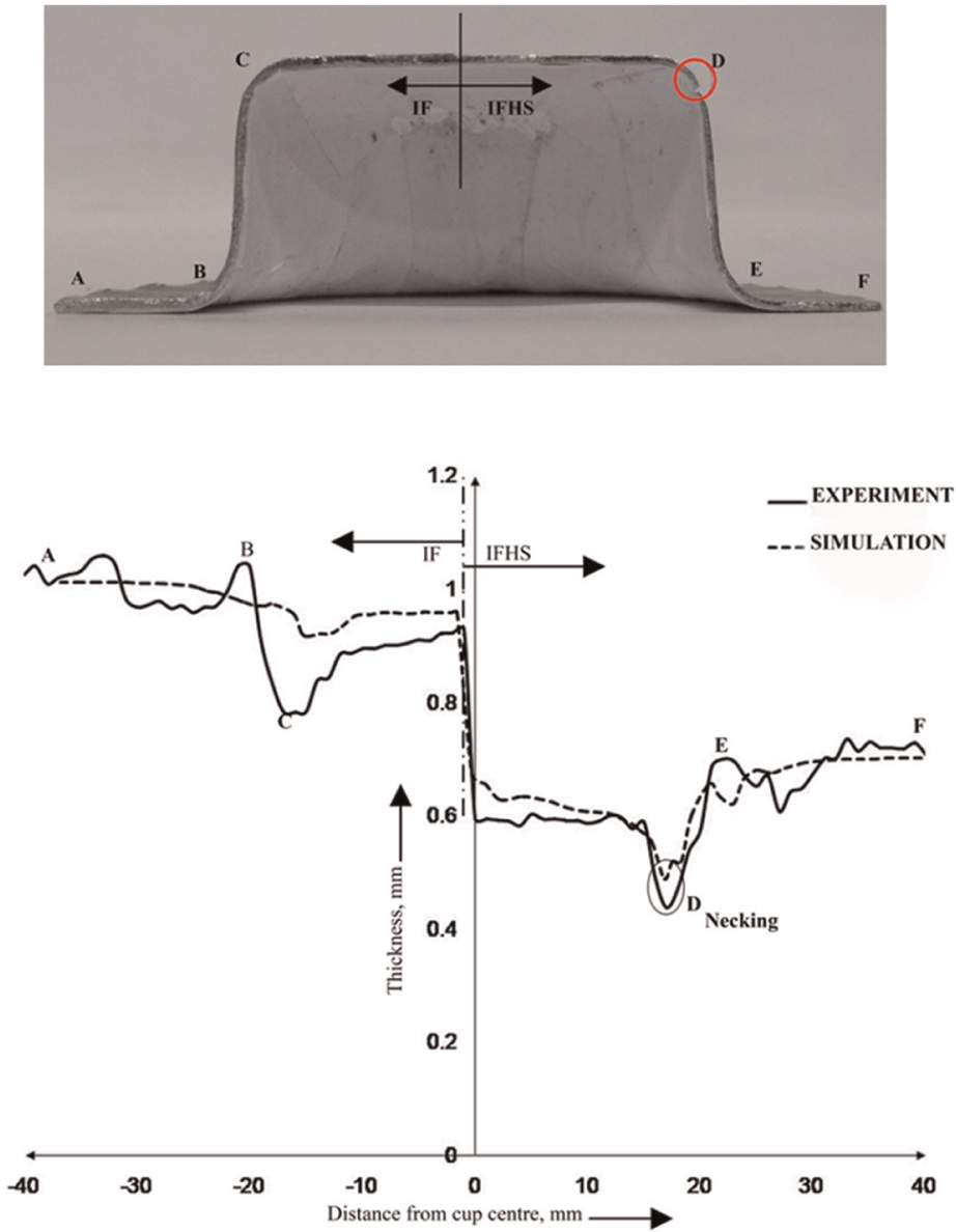
The cylindrical TWB cups drawn were cut into two parts along the RD, and the thickness variation was measured across the weld using a pointed anvil micrometer of least count of 0.01 mm. Figure 7 compares the experimentally measured and numerically predicted thickness distributions of the IF-HSLA TWB cup. In experiment, reduction in thickness on the flat portion of the cup (cup bottom) was negligible in the IF-HSLA TWB. The maximum thinning took place at the cup corner in the HSLA steel side (at location D), and thickening was observed at the flange (at locations A and E). While using von Mises yield criterion, maximum thinning was found on the weaker IF side. However, FE simulations incorporating Hill’s yield criterion predict maximum thinning to be occurring on the cup corner in the stronger HSLA side. This reveals the influence of R-value on thinning during deep drawing of TWBs of different material combination. Figure 8 compares the thickness distribution of IF-IFHS TWB cup. In this TWB, reduction in thickness was observed on the flat portion of the cup, although necking occurred at the cup corner in the thinner IFHS side (location D). Minimum thickness values of 0.44 and 0.49 mm were observed in experiment and simulation, respectively. It was observed that FE simulations incorporating the Hill’s yield criterion predicted maximum thinning and failure location in both the TWB cups.
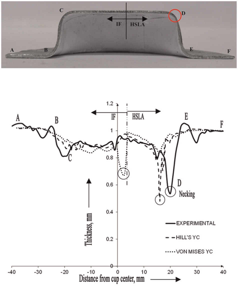
Comparison of thickness distribution in IF-HSLA TWB cup measured experimentally and predicted numerically.
Comparison of thickness distribution in IF-IFHS TWB cup measured experimentally and predicted numerically.
Weldline movement
The weldline displacement from its initial position was observed in the drawn TWB cup (Figure 9), and the displacement was measured using a bridge-type coordinate measuring machine (CMM) with least count of 0.001 mm. Figure 10 compares the weld movements measured in experiment with those predicted by FE simulations. A maximum weld displacement of 2.57 mm toward HSLA (stronger) side at the cup bottom and 4.02 mm toward IF (weaker) side on the flange was observed in the IF-HSLA TWB. Hill’s yield criterion predicted the weld movement more accurately than the von Mises criterion. The nonuniform drawing of sheet metal into the die cavity from the flange caused the weld movement in the TWBs. In IF-IFHS TWB, the weld moved toward IF (thicker) side at the cup center and IFHS (thinner) side at the cup flange. However, lesser movement was observed in IF-IFHS TWB compared to IF-HSLA TWB.
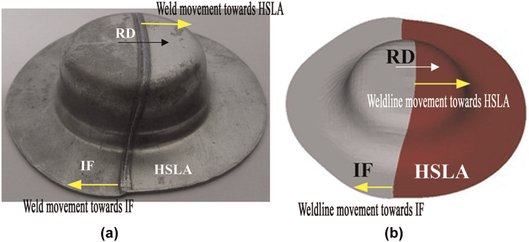
Weldline movement in IF-HSLA TWB at cup center and flange: (a) experiment and (b) FE simulation.
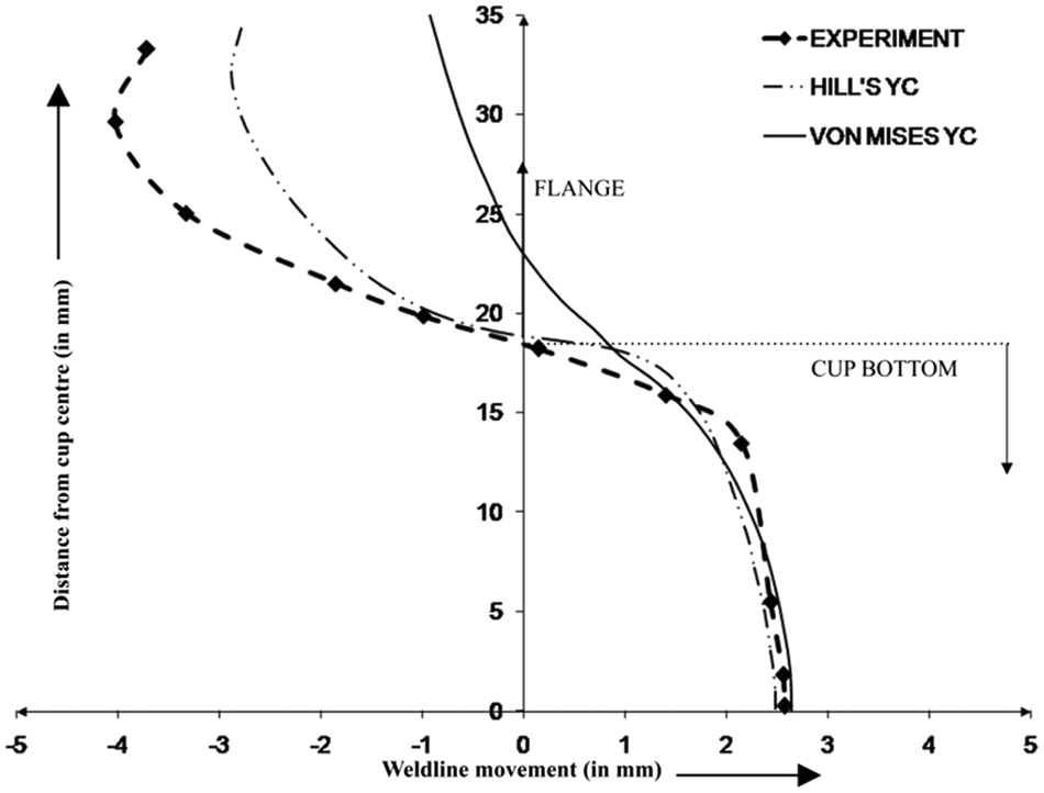
Prediction of weldline movement in IF-HSLA TWB.
Conclusion
The formability characterization of IF, IFHS and HSLA anisotropic steel sheets with IF-IF LWBs was studied. Formability of IF-HSLA and IF-IFHS TWBs of different material and thickness combination was evaluated experimentally and numerically. The following are the main conclusions from this study.
In all uniaxial tensile tests of LWBs and TWBs, the failure/fracture occurred in the parent metal and away from the weld, which confirmed sufficient weld strength without any defects. Fracture occurred in the weaker or thinner side for all the LWB and TWB specimens due to strain localization in those parts. All these results are in good accordance with previous reported studies.
The cup depth of the LWBs decreased marginally by 5%–7% compared to the respective parent metal, and this was due to negligible influence of a very narrow weld zone (0.5–0.7 mm) where the local metallurgy was different from the parent metal. However, formability of IF-HSLA TWB decreased by 37% compared to parent IF steel sheet. This was due to nonuniform thickness distribution in the deformed cup leading to thinning and subsequent failure in the HSLA side due to its lower R-value. Fracture was observed in the stronger IFHS side for IF-IFHS combination as IFHS has lower thickness.
Thinning was observed to be more compared to other locations at the punch corner for both the sides of IF-HSLA deep drawn cup. A thinning of 0.81 mm was observed in the cup corner of IF side, but a maximum thinning of 0.54 mm was observed at the cup corner in the stronger HSLA side of TWB, which led to failure. This was completely different from failure location in the uniaxial tensile TWB specimen, where the fracture took place in IF side. Localized thinning occurred in the HSLA side as it has low
The FE results revealed that incorporation of von Mises yield criterion predicted failure in the weaker IF steel and close to the weld. However, incorporation of Hill’s yield criterion with Lankford anisotropy parameter into FE model predicted the failure location exactly same as the experimental observation. Hence, it is concluded that anisotropy parameter, R-value, influences the failure location in TWBs.
Weldline movement was observed in TWB cup due to nonuniform drawing of sheet materials into the die cavity from the flange leading to decrease in cup depth. The Hill’s yield criterion predicted the weld movement more accurately than the von Mises criterion. Hill’s yield criterion incorporates anisotropy and thus can predict weldline movement in the flange region better than von Mises yield criterion. Maximum weldline movement in the flange region of IF-HSLA TWB was recorded as 4.02 mm. However, simulation incorporating von Mises and Hill’s yield criterion predicted maximum weldline movement to be 1 and 3 mm, respectively.
Footnotes
Appendix 1
Acknowledgements
The authors are thankful to Dr R. Verma of TATA steel and Dr A. Das of ESSAR steel for providing the steel sheets. Metallographic and computational facilities provided by Steel Technology Centre, IIT Kharagpur, are greatly acknowledged. This article is a revised and expanded version of the article entitled “Influence of Anisotropy Parameter in Deep Drawing of Tailor Welded Blanks” presented at AIMTDR 2013 (14–16 December) JU, Kolkata, West Bengal, India. The authors are also thankful to the conference organizers for giving permission for publication of this research work.
Declaration of conflicting interests
The authors declare that there is no conflict of interest.
Funding
This research received no specific grant from any funding agency in the public, commercial or not-for-profit sectors.