
Abstract
Tailor-welded blank is one of the promising technologies in the application of lightweight materials for auto body parts manufacturing. The material discontinuity across the weld line results in an inhomogeneous deformation and weld line displacement. In this study, a two-dimensional analytical model is proposed to predict the tension distribution along the cross section. An energy method is used to calculate the restraining force due to bending, sliding, and unbending phenomena on the die and punch radii. To control the weld line movement, a blank holder force control strategy is proposed to achieve force equilibrium at the bottom of the part across the weld line. Finite element simulations are performed to study the effect of die and punch radii, friction coefficient, thickness ratio, and blank holder forces on the weld line displacement in strip drawing process. Under a uniform blank holder force, the weld line moves toward the thicker/stronger side implying a higher blank holder force is required for the thinner/weaker side. The results show that the weld line displacement can be controlled by an appropriate blank holder force adjustment. In order to control the weld line movement in square cup deep drawing, blank holder force on the thinner side is increased and its influences on the deformation process are investigated. Comparisons of material draw-in, weld line movement, and forming force show a good agreement between the theoretical, numerical, and experimental results.
Keywords
Introduction
In the field of the manufacture of automotive sheet components, nowadays, lightweight materials and designs are in the spotlight due to their considerable influence on savings in energy consumption. In this regard, the substitution of monolithic blanks with equivalent tailor-welded blanks (TWBs) has been proven to be a promising strategy to achieve the aforementioned goal and also crashworthiness improvement of vehicle structure. The implementation of TWBs, which consist of base blanks with differences in the thickness, coating, or mechanical properties consolidated into a single blank with a desirable layout using an appropriate welding process prior to the forming, also results in a higher performance of automotive sheet structures and a more efficiency in using materials and hence leads to a reduction in manufacturing costs. 1
A successful utilization of TWBs to meet the requirements of industry is, however, dependent on how much the important concerns associated with the forming of TWBs can be alleviated. One of the problematic issues affecting formability, springback, and quality of a product is the tendency of the weld line to move toward the thicker or stronger base blank. 2 The weld line movement can be attributed to uneven deformations developed in the base blanks in each side of the weld line. In order to control and reduce the weld line movement, some approaches have been proposed such as using appropriate blank holder forces (BHFs),3–6 draw beads,7,8 and constraining weld line.9–11
The possibility of using a non-uniform BHF with respect to the thicker and thinner sides was experimentally and numerically investigated by Ahmetoglu et al. 3 to reduce the weld line movement in the circular cup drawing of a circular AKDQ steel TWB with the difference in the thickness. It has been shown that the deformation in the thinner blank as well as the movement of the weld line can be controlled using the proposed method of applying local BHF. Based on a two-dimensional (2D) analytical model and assuming a non-uniform BHF, He et al. 4 predicted the required BHFs on each side of a TWB with difference in thickness to suppress the weld line movement and increase the formability. In their analytical model, the effect of bending and unbending on the tension increase was neglected. The experiments and finite element (FE) simulations were conducted to validate the analytical model and further study the deep drawing of TWBs. As proven by the experiment and the analytical model, the BHF over the thinner side should be higher than the one on the thicker side to prevent the weld line movement and achieve a higher formability. Using an implicit FE code, the deep drawing of TWBs made of dissimilar materials was simulated by Padmanabhan et al. 5 to investigate the thickness distribution, the punch force, and the weld line movement. A non-uniform BHF was utilized to enhance the formability and control the draw-in of aluminum–steel TWBs. Hu et al. 6 carried out some simulations on the deep drawing of a square cup made from a TWB of different thickness with a non-linear weld line under a set of non-uniform BHFs. It was observed that by increasing the BHF on either the thicker or thinner side while the BHF on the other side is kept constant, a more weld line movement occurs toward the thicker side at the bottom of the part and a less movement takes place toward the thinner side at the flange area.
Choi et al. 12 reported that the blank shape of TWBs and the initial position of the weld line are two effective parameters on the weld line movement and hence cannot be neglected. In the case of the circular TWB, smaller movements of weld line were observed compared to the ones in the square TWB. It was concluded that by positioning the weld line further away from the center line of the cup, the amount of the weld line movement and deformations increase. It has also been shown7,8 that the weld line movement in the box drawing of TWBs with different thickness combinations can be controlled using an appropriate layout of circular draw beads in the thinner side.
Kinsey et al. 9 simulated the deep drawing of a car door inner panel from an aluminum TWB with a non-linear weld line using an FE model considering clamping components along the weld line in specified locations to restrict any movement. A reduction in the weld line movement, an increase in the drawability, and a more uniform strain distribution were observed by utilizing the proposed arrangement of restriction forces on the weld line. The effectiveness of a stepped blank holder and weld line clamping pins on the weld line movement and the thickness reduction in the box drawing of steel TWBs were assessed by Chen et al. 10 through experiments and FE simulations. Among the 12 schemes consisting of the flat or stepped blank holder with or without clamping pins for each of three considered forming depths, the ones utilizing both the stepped blank holder and weld line clamping pins were the most effective to obtain a sound quality with a reduced weld line movement. Morishita et al. 11 proposed a new method to eliminate the weld line movement and consequently enhance the formability in the square cup drawing of TWBs with the material combination of mild steel–high-strength steel by utilizing a counterpunch which can be applied either on the whole bottom of the part or only on the thicker (stronger) portion. The experimental results showed that the formability can be significantly improved by increasing the counterpunch pressure.
Using limiting dome height tests, it was demonstrated by Panda and Kumar 13 that in plane strain stretching of TWBs with difference in thickness and properties, the weld line movement can be affected by the weld orientation such that it is higher for the case in which the weld line is parallel to the width compared to the one in which the weld line is parallel to the length. It was also reported that the weld line movement is higher in the TWB with different thickness than that of different properties. Conducting a similar experimental and numerical study on the biaxial stretch forming of IF steel TWBs with difference in thickness, 14 they showed that the amount of the weld line movement increases as the thickness ratio increases and then becomes constant beyond a certain value of the thickness ratio. An increase in the weld line movement by increasing the thickness ratio has also been reported by Korouyeh et al. 15 in the ball punch test of st12 steel TWBs through the experiment and by Aurelian 16 in the square cup drawing of AA5182 TWBs predicted by FE simulations.
The formability of tailor-welded dual-phase steel blanks was compared with that of the parent metals by Bandyopadhyay et al. 17 through experiments and FE simulations. Due to the existence of a soft zone in the heat-affected zone, the formability of laser-welded blanks evaluated using the Erichsen cupping test was lower than that of the monolithic blanks. Vasudevan et al. 18 experimentally and numerically considered the deep drawing of TWBs of low-carbon steels with different material and thickness combinations. They showed that the Lankford coefficient can affect the weld line movement and the fracture location in deep drawn TWBs. Lee et al. 19 investigated the mechanical properties and the formability of TWBs with different thickness made from boron steels using the laser welding process. The hot Erichsen test and the tensile test were implemented to examine the effect of different conditions.
As briefly reviewed above, most of the studies have employed numerical simulations and physical experiments to investigate the weld line movement in forming TWBs. Besides, due to bending and unbending at the corner of the die and punch, the effect of tension increase in the base blanks would be an important issue in an analytical model, which was neglected in the article by He et al. 4 with non-uniform BHF assumption and simply considered in the article by Kinsey and Cao 20 with assuming uniform BHF.
In this study, the deep drawing of IF steel TWBs with difference in thickness under a non-uniform BHF is considered. By developing an analytical plane strain model, the effect of some parameters on the non-uniform BHF required to suppress the weld line movement is studied. Unlike He et al. 4 and Kinsey and Cao, 20 the tension increases as a consequence of bending and unbending is incorporated more accurately into the analytical model based on the virtual work principle proposed by Chen and Tszeng. 21 The experiments and FE simulations are conducted to validate the results of the analytical model and further study the weld line movement. As an application of the non-uniform BHF, the weld line movement in the square cup drawing is investigated using the FE model and the experiment.
2D analytical model
Figure 1 shows the 2D plane strain model of the deep drawing process proposed by Marciniak et al.
22
In this model, the through-thickness stress is assumed to be negligible. In Figure 1,
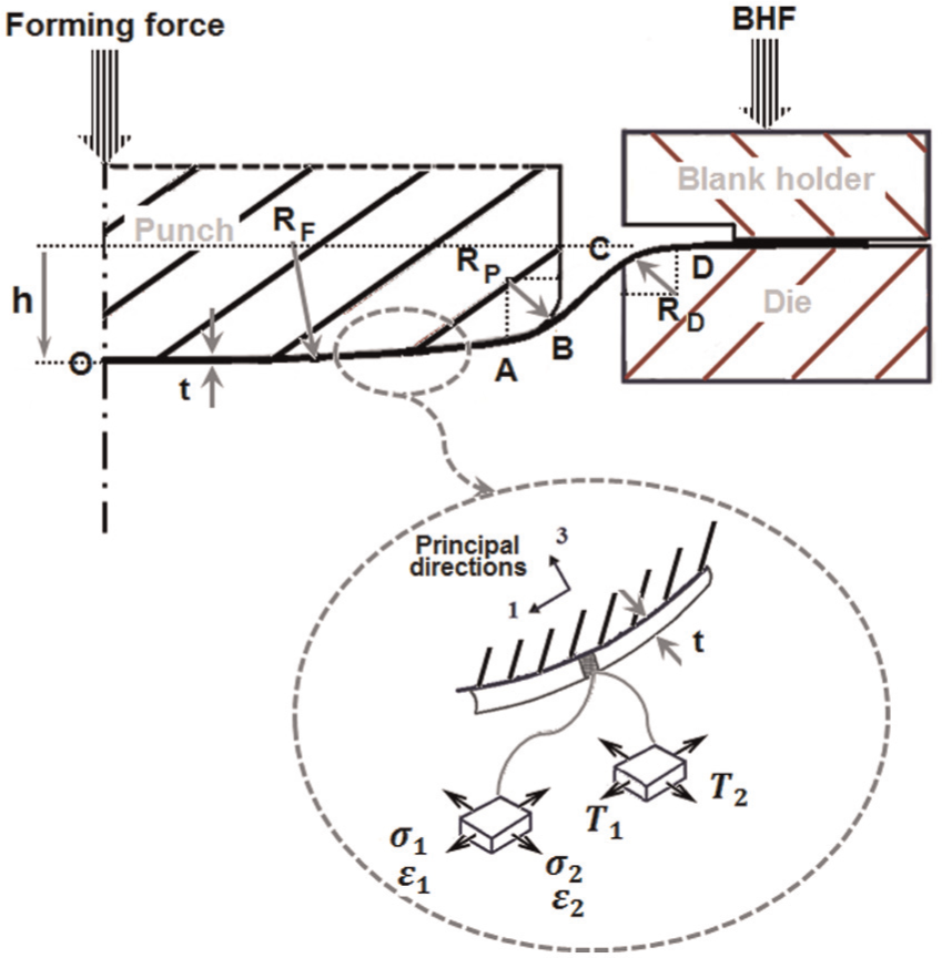
The 2D plane strain model of the deep drawing process.
By considering an element of the sheet like the element shown in Figure 1 for the contact area of the sheet and punch face and under the plane strain and incompressibility conditions, the strain state can be written as follows
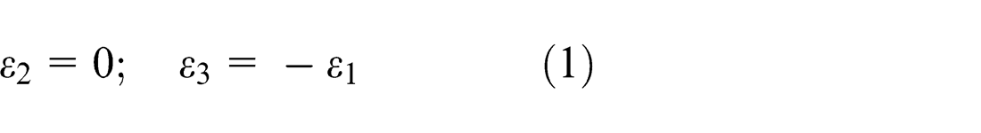
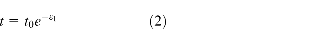
where 1, 2, and 3 are the local principal directions along the section profile, perpendicular to the section, and through the thickness, respectively. At any instant, the thickness of the sheet can be expressed as
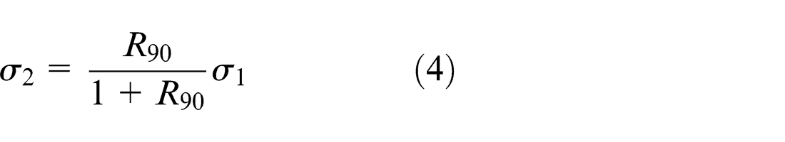
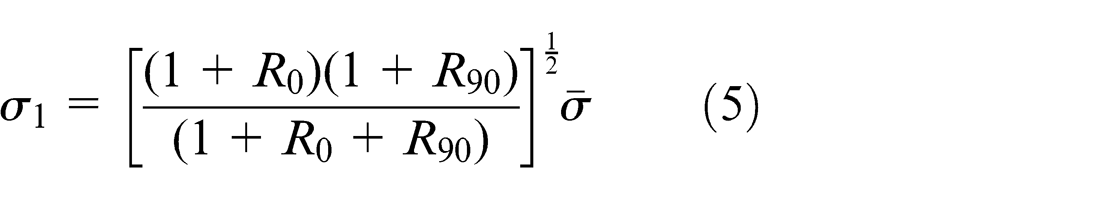
in which
where
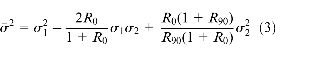
Substituting equation (4) into equation (3) yields
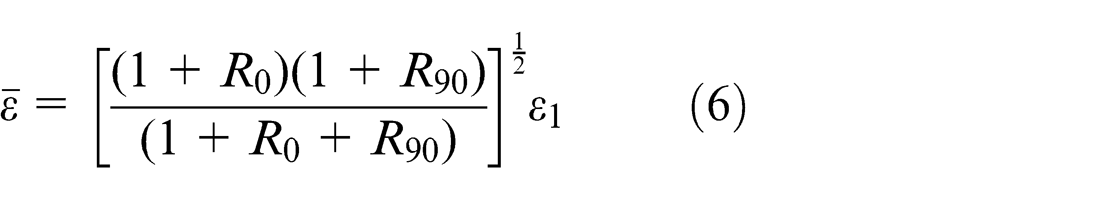
The equivalent strain is therefore obtained as
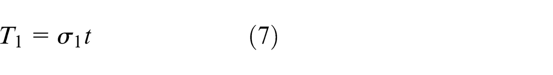
The force per unit width of the sheet in direction 1 can be written as follows
Assuming the power law strain hardening,
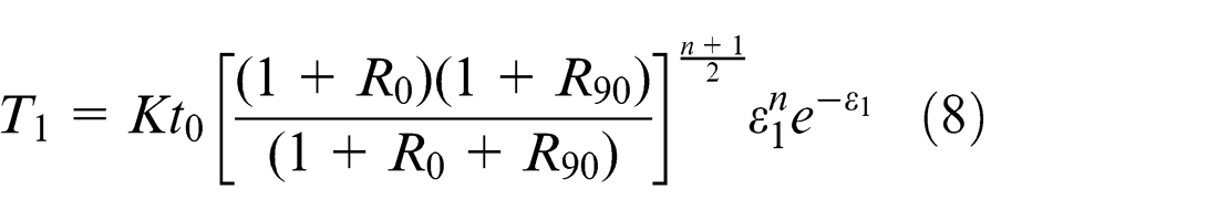
where
To determine
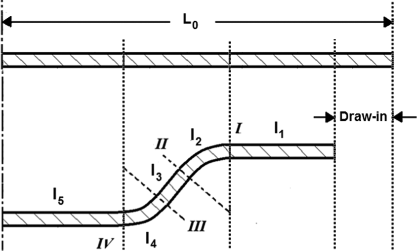
Assumed sections and segments in the blank.
Applying force equilibrium at section I, tension
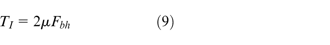
in which
Tension
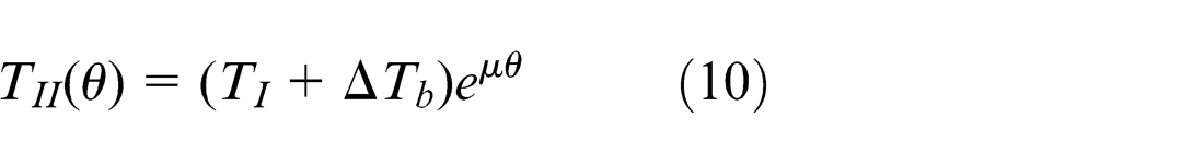
where
Neglecting the friction between the side wall and the punch, the tension throughout the side wall would be constant and
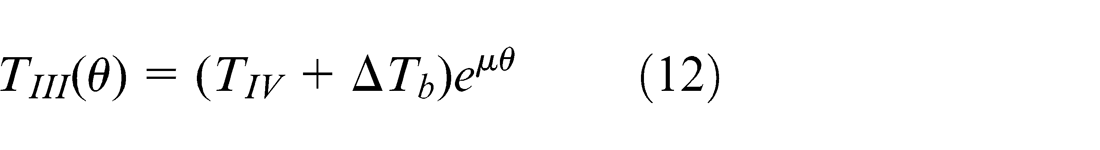
Taking into account the material flow sliding outward from the center O, like equation (10) the following relation can be expressed for the tension at sections III and IV considering the tension increase at the punch corner radius
In this article, the theoretical model based on the principle of virtual work, proposed by Chen and Tszeng
21
to estimate the draw-bead restraining force, is implemented for calculating the tension increase
It is now possible to obtain the principal strain along direction 1, that is,
Using the condition of volume constancy during the plastic deformation, the amount of the material draw-in (Figure 2) can be predicted at each stroke of the punch. In this way, the length and the thickness of all segments should be determined at considered strokes. Regarding Figure 2, lengths
In this study, strains and tensions are calculated at each increment of forming height
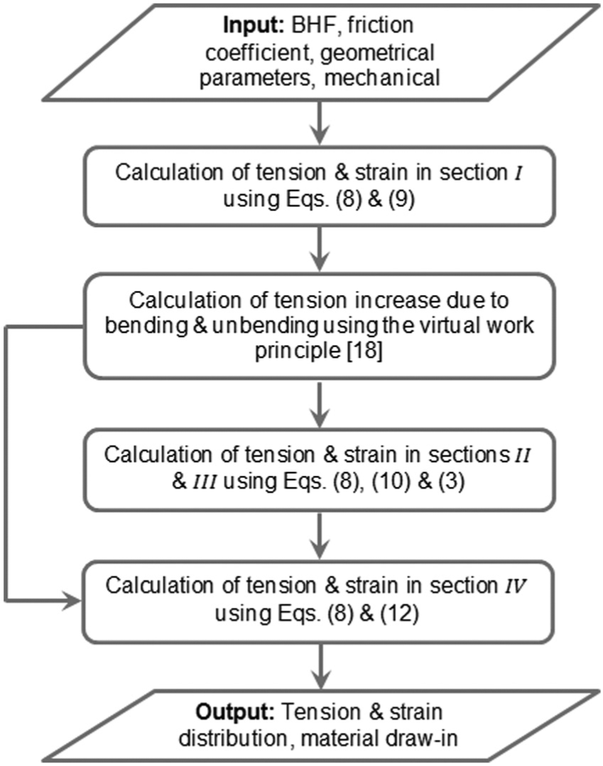
Utilized procedure for the 2D analytical model.
Since asymmetry with respect to the weld line exists in TWBs, a different material flow can be observed in each blank. This inhomogeneity in the material flow leading to the different draw-in and the weld line movement is the result of different states of stress and strain occurred in each blank. In the case of TWB with difference in thickness, the tension increase in the thicker blank due to bending and unbending is much higher than the thinner blank. According to the theoretical model explained above, the tension increase also affects friction forces at the die and punch corner. Consequently, the resultant tension will pull the weld line toward the thicker blank side and the material draw-in of the thinner side would be larger.
Parameters such as BHF, die corner radius, friction coefficient, and draw beads, that redistribute and balance the resultant tension across the weld line would prevent weld line movement. Since the BHF is one of the most effective parameters on the tension distribution at the various sections of the blank, it is appropriate to use different BHFs on each blank instead of similar ones. Neglecting small plastic strains, the following condition must hold at the bottom of the part to satisfy the equilibrium preventing the weld line movement
For instance, the BHF on the thicker side can be determined first and then the tension
FE model
A simplified elastoplastic FE model was established using ABAQUS/Explicit to simulate and further study the deep drawing of TWBs with different thickness combinations. Both uniform and non-uniform clamping forces are incorporated into the model by considering a segmented blank holder. The four-node shell elements S4R with 2 mm × 2 mm size and five integration points through the thickness are used to model the initial blank as illustrated in Figure 4. Smaller elements are used in the vicinity of the place in which the thickness change has occurred. The punch, die, and blank holder are also discretized using the rigid shells R3D4. Like the theoretical model presented above, strain hardening and anisotropy are considered to describe the plastic behavior of the sheet. The mechanical properties of the sheet and the dimensions of the die set and blank are presented in the next section. The weld zone properties are ignored for simplicity. Based on sensitivity analyses and regarding the drawing depth, the velocity of the punch is set to 3000 mm/s with the appropriate amplitude in which the ratio of the kinetic energy to the internal energy is negligible. Considering the symmetry existing in the box drawing and due to the thickness change in the blank, a half of the process is modeled as shown in Figure 4(b). Therefore, symmetry boundary condition is imposed on the corresponding edge of the sheet. Friction between the sheet and die components is defined by Coulomb’s friction law with different friction coefficients in the range of 0.05–0.1, as considered by He et al. 4 . The solving time required by the FE model for simulating the strip and box drawing varies from a simulation to another due to the implementation of different fine elements in the vicinity of the place in which the thickness change occurs for various cases. For the strip and box drawing, it varies from 40 to 50 min and from 90 to 120 min, respectively.
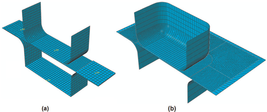
FE model of (a) strip and (b) square cup deep drawing utilized in the simulations.
Experimental work
In order to assess the capability of the proposed analytical and FE models, strip drawing and square cup drawing of both monolithic and TWBs were conducted experimentally. IF steel sheets of grade DX540 were used as the experimental material. Tensile tests at 0°, 45°, and 90° from the rolling direction according to ASTM-E8 were performed to obtain the mechanical properties of the IF steel sheet as presented in Table 1.
Mechanical properties of IF steel sheet of grade DX540.
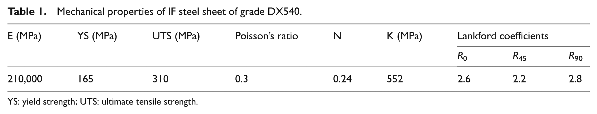
YS: yield strength; UTS: ultimate tensile strength.
The TWBs with the thickness combination of 0.77 and 1.17 mm and dimensions of 185 × 35 mm and 185 × 185 mm were used for the strip and square cup drawing, respectively. The CO2 laser-welded blanks were supplied by Supplying Auto Parts Company (SAPCO). The monolithic blanks of 0.77 and 1.17 mm thicknesses were also considered in the experiments. A die with a segmented blank holder capable to exert different clamping forces on each side of the weld line was utilized. The punch dimensions are 100 × 100 mm. The clearance between the die and the punch and the corner radius of both the punch and the die are, respectively, 2 and 15 mm. All tests were carried out on a 50-ton hydraulic press. Figure 5 depicts the experimental deep drawing setup.
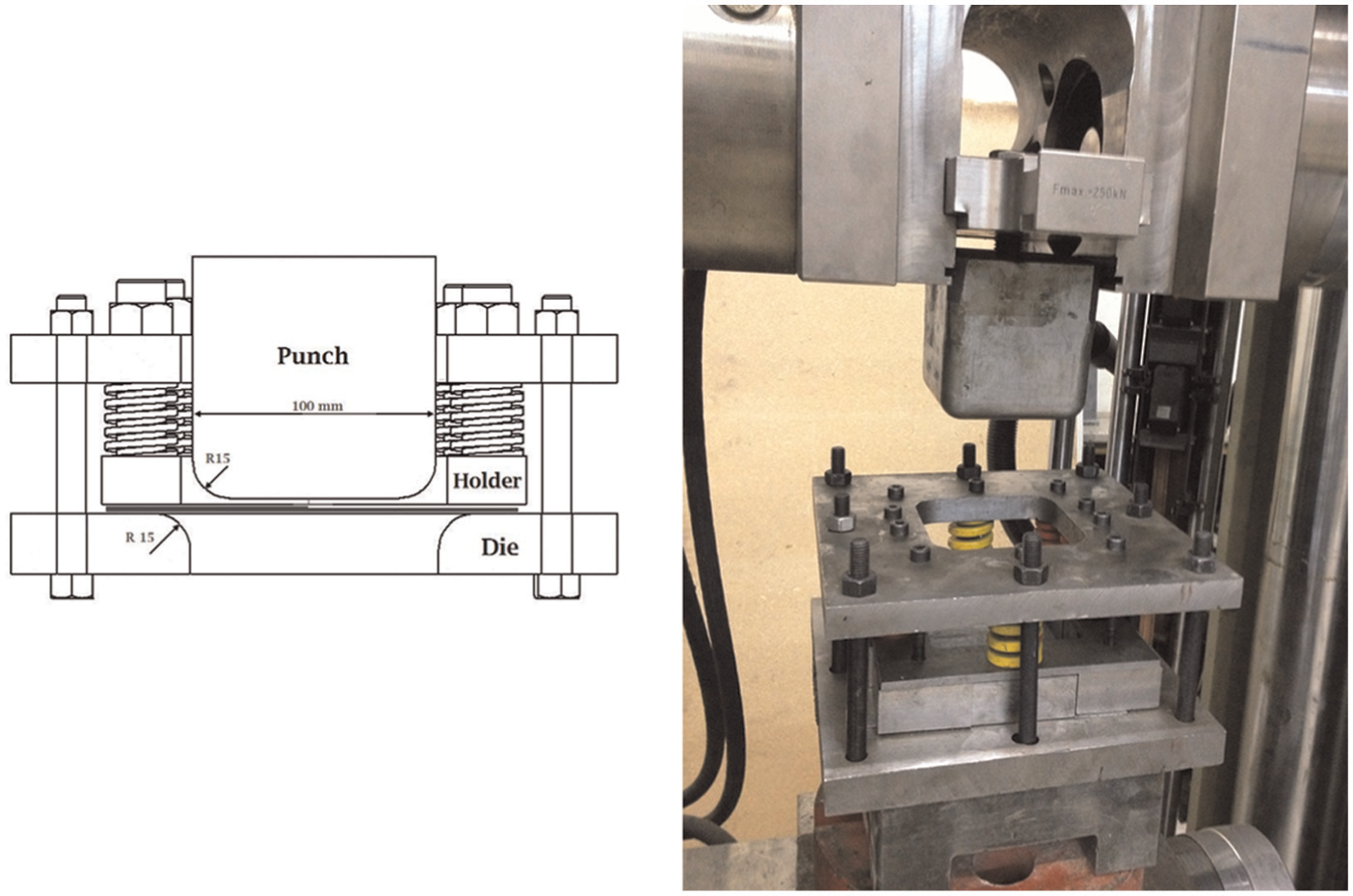
Experimental platform used in the experiments.
Results and discussion
Validation results
To prevent weld line movement, the analytical model illustrated in Figure 3 is utilized for the strip drawing at the experimental conditions mentioned before with a prescribed BHF of 2.45 kN on the thicker side. Implementing a trial-and-error procedure and using the equivalent FE model and the experiment, the corresponding BHF on the thinner side leading to a weld line movement of about 0can also be found. Table 2 compares the predicted BHFs on the thinner side with the experimental ones. As compared to the result obtained from analytical model having a reasonable agreement with the experimental value, the predicted clamping force using FE model is much closer to the experimental one. This is due to the simplifications involved in the analytical method as mentioned before. However, the analytical model can easily be implemented and is capable to calculate BHF on the thinner side associated with a predefined BHF on the thicker side in only a few seconds when compared to the FE model by which this can take hours. So, it would be appropriate to utilize the analytical model for anticipating an initial value and then use FE model to predict a nearly exact one by some trials around the predicted value.
Predicted and obtained BHFs on the thinner side to reduce the weld line movement (the thickness combination is 0.77 and 1.17 mm).
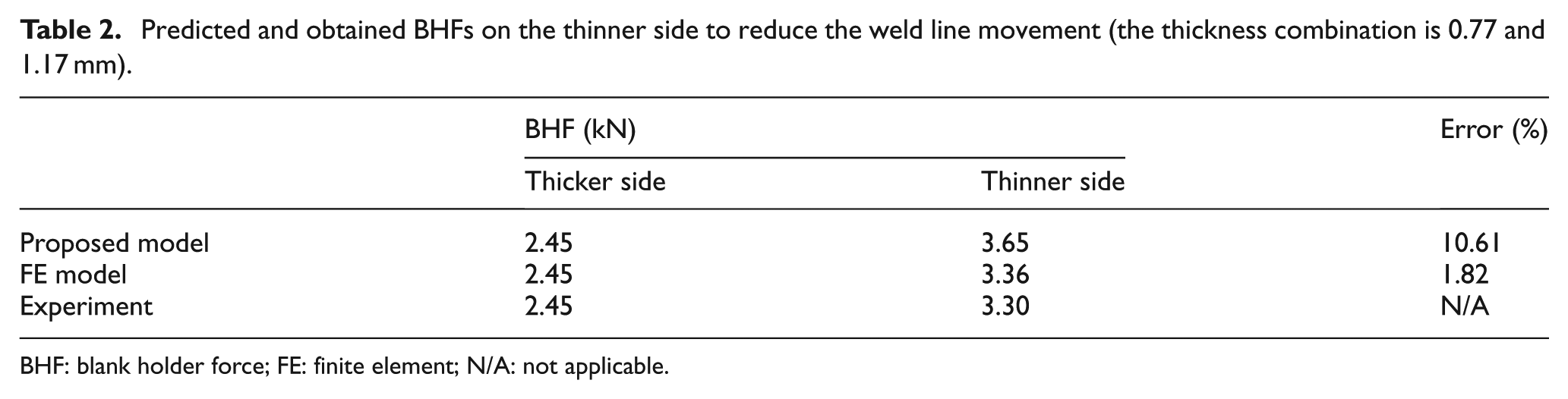
BHF: blank holder force; FE: finite element; N/A: not applicable.
Figure 6 shows the strips deep drawn at various BHFs and the corresponding configurations predicted by the FE model. The values of draw-in and weld line movement obtained using the FE model are compared with those of the experiment in Table 3, showing a good agreement between them. The average and maximum differences between the experimental and predicted results are 8.6% and 13.9%, respectively. For further comparison, Figure 7 shows the punch force–stroke diagram required to form a strip using the BHF combination of 2.45 and 3.30 kN at which the weld line movement is eliminated as found experimentally (see Table 2).
Comparison of the draw-in and the weld line movement at various BHF ratios obtained by the FE model and the experiment.
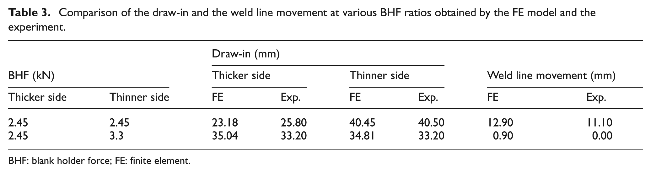
BHF: blank holder force; FE: finite element.
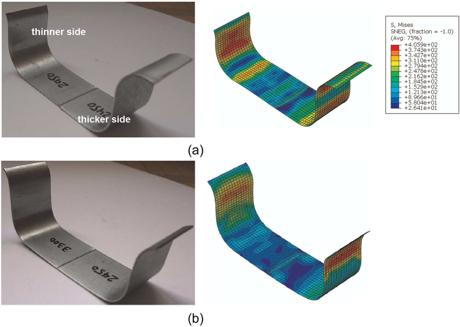
Experimental and simulated deformed parts at various BHF ratios.
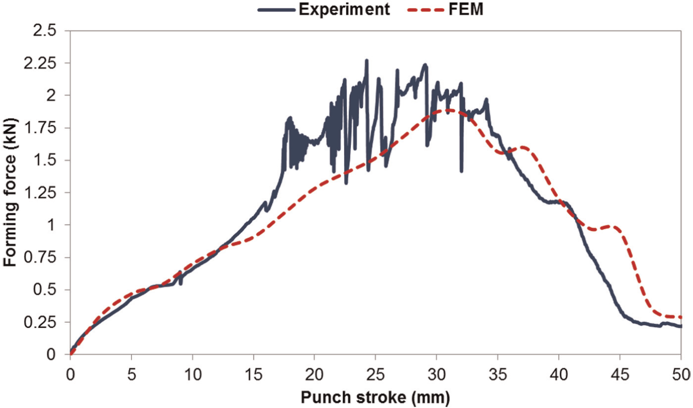
Comparison of experimental and predicted forming forces. The BHF and the thickness combinations are, respectively, 2.45 and 3.3 kN and 0.77 and 1.17 mm.
As illustrated above, the results from the analytical and FE model are in good agreement with those of the experiment. In the following sections, the mentioned models are utilized to study the deep drawing of TWBs under the uniform and non-uniform BHFs.
Weld line movement
In order to reduce the weld line movement under the condition of a uniform BHF, higher clamping forces should be applied. This reduction in the weld line movement continues until the blank is released from under the blank holder. So, Figure 8 illustrates the material draw-in and the weld line movement for different BHFs at the punch stroke of 35 mm. As a higher BHF is applied, the amount of draw-in at the thinner and thicker sides becomes smaller and larger, respectively, and, therefore, the weld line movement decreases.
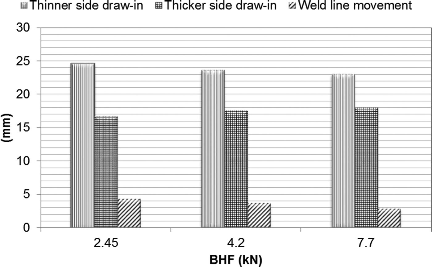
Material draw-in and weld line movement in deep drawing of TWB under various uniform BHFs predicted using the FE model.
As demonstrated above, however, there would be a difference between tensions induced in the two sides during the deep drawing of a TWB with different thicknesses under a uniform BHF. Therefore, an undesirable weld line movement occurs. To eliminate the tension difference, a non-uniform BHF consisting of two different forces applied separately on each side of the weld line can be used in such a way that the BHF on the thinner side should be higher than that on the thicker side because of the weld line movement toward the thicker side. The effect of the BHF ratio of the thinner side to the thicker side on the weld line movement and the material draw-in, obtained using the FE model, is shown in Figure 9. The thickness combination and the BHF over the thicker side is, respectively, 0.77 and 1.17 mm and 2.45 kN. From the figure, it can be concluded that increasing the BHF ratio from 1 to 1.37 leads to the more symmetric material draw-in and the less weld line movement. By further increasing the BHF ratio, a reverse weld line movement toward the thinner side happens.
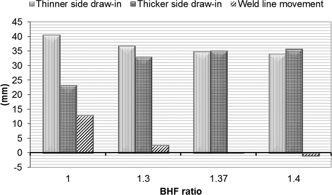
Effect of the BHF ratio on the weld line movement and the material draw-in predicted by the FE model (BHF on the thicker side = 2.45 kN).
Utilizing the proposed analytical model, it is possible to predict the required amount of the BHF on the thinner side with respect to the BHF applied on the thicker side to prevent the weld line movement. Figure 10 shows the effect of the BHF over the thicker side on the necessary BHF ratio at various thickness ratios. The thickness of the thicker side is 1.17 mm and other parameters are the same as those mentioned in the experimental work. As can be seen in Figure 10, by increasing the BHF over the thicker side, the BHF ratio decreases. This is due to the fact that the difference between tensions in both sides of the weld line is mainly related to the amount of tension increase at the die and punch corners. The increase in tension due to bending and unbending with considering pre-tension induced by the BHF has previously been calculated using the virtual work principle. By increasing the pre-tension in the sheet, the tension increase due to bending decreases. 4 Accordingly, as the BHF which directly affects the pre-tension increases, the difference between tensions in the thicker and thinner sides decreases and, therefore, the weld line movement becomes smaller. Hence, a smaller increase in the BHF over the thinner side is required.
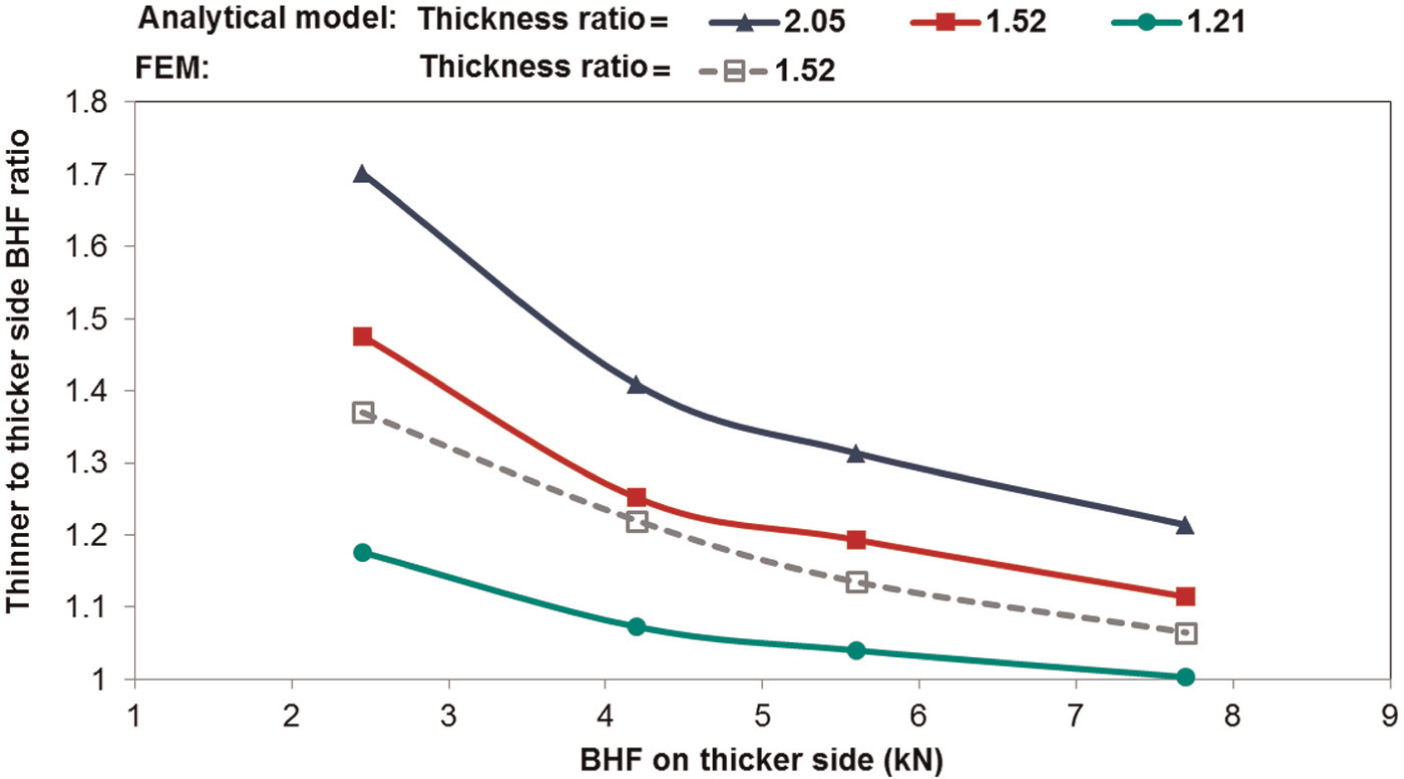
Effect of BHF over the thicker side on the necessary BHF ratio predicted using the analytical model to prevent the weld line movement.
The influence of the thickness ratio of two sides on the BHF ratio at different BHFs for the thicker side is depicted in Figure 11. When the thickness ratio becomes larger, the tension difference between the thicker and thinner sides increases, which leads to more weld line movement. Hence, it is necessary to increase the BHF more on the thinner side to prevent such a movement, as shown in Figure 11. The increased weld line movement as a result of the higher thickness ratio is demonstrated in Figure 12 for two different friction coefficients. At the considered range for the friction coefficient, this figure also shows the negligible dependency of the weld line movement on the friction coefficient.
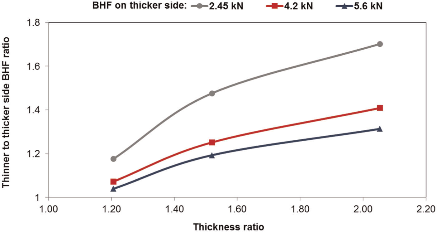
Effect of thickness ratio on the necessary increase of BHF over the thinner side predicted using the analytical model to prevent the weld line movement.
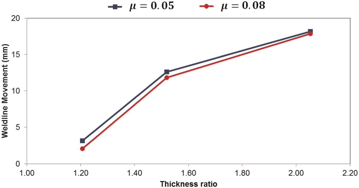
Variation in the weld line movement with changing thickness ratio obtained by the FE model at a uniform BHF for two different friction coefficients.
The variation in the required BHF in order to prevent the weld line movement with the die corner radius can be studied as the following two cases. In the first case, the same die corner radius is assumed for both sides. The effect of the die corner radius on the BHF ratio is illustrated in Figure 13 at various BHFs on the thicker side. The thickness combination is 0.77 and 1.17 mm. It can be seen from the figure that at a constant BHF over the thicker side, a decrease in the die corner radius leads to the higher BHF to be applied on the thinner side. In other words, the weld line movement toward the thicker side becomes more significant by decreasing the die corner radius and, consequently, higher BHF is needed over the thinner side.
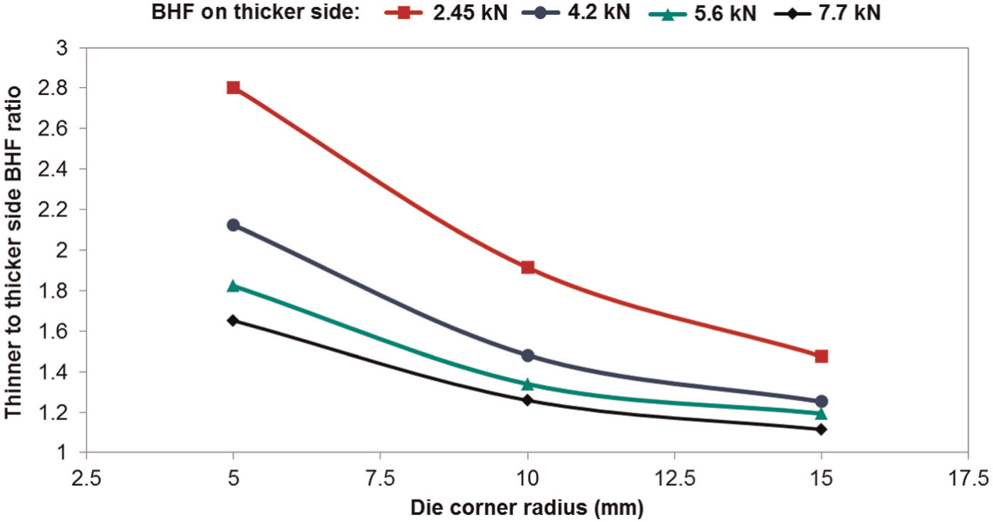
Variation in required BHF ratio with the die corner radius.
For the other case, a different corner radius is considered for each side. Figure 14 shows the influence of the die corner radius at the thinner side on the BHF ratio for two different thickness ratios. The die corner radius and the BHF at the thicker side are considered as 15 mm and 2.45 kN, respectively. As seen, by decreasing the corner radius associated with the thinner side, the required BHF ratio decreases so that the values lower than unity can be reached, which is the case of the thickness ratio of 1.52 in Figure 14. Such a value means that a lower BHF should be applied over the thinner side than that applied over the thicker side because of the weld line movement toward the thinner side. Figure 15 demonstrates the effect of the die corner radius at the thinner side on the weld line movement, obtained using the FE model, under the uniform BHF of 2.45 kN. At the smaller die corner radius, the tension increase due to both bending and unbending and correspondingly the tension in the thinner sheet would be higher so that it might reach or exceed the tension in the thicker side, which results in a reduced weld line movement or, reversely, the one toward the thinner side, as depicted in Figure 15. In this figure, the positive and negative values are, respectively, related to the weld line movements toward the thicker and thinner sides. It is worth noting that increasing the die corner radius at the thicker side under a constant die corner radius at the thinner side has the same effect on the weld line movement and the required BHF ratio as discussed above.
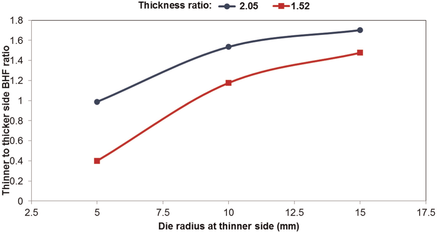
Variation in required BHF ratio with the die corner radius at the thinner side. At the thicker side, the die corner radius is 15 mm.
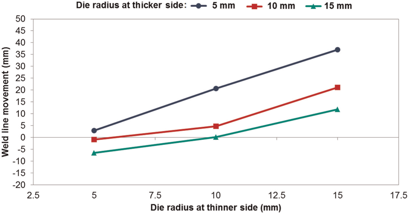
Variation in weld line movement with the die corner radius at the thinner side obtained using the FE model under a uniform BHF.
Application to square cup drawing
The effects of the uniform BHF and the thickness ratio on the weld line movement, obtained using the FE model, are demonstrated in Figure 16. At the center of the part (the origin of the curve), the weld line moves toward the thicker side (positive values) and gradually the movement reduces to 0 at the wall of the cup (approximately 80 mm) and then reaches negative values at the flange region, which means a reverse weld line movement toward the thinner side. This movement toward the thinner side can be attributed to the difference in the material flow velocity between the thicker and thinner sides around the weld line on the flange region at which the thinner side is drawn into the die more rapidly than the thicker side. It can be seen in Figure 16 that at a constant BHF, by increasing the thickness ratio, the weld line movement increases and also for a known thickness ratio, by increasing the uniform BHF, the weld line movement decreases.
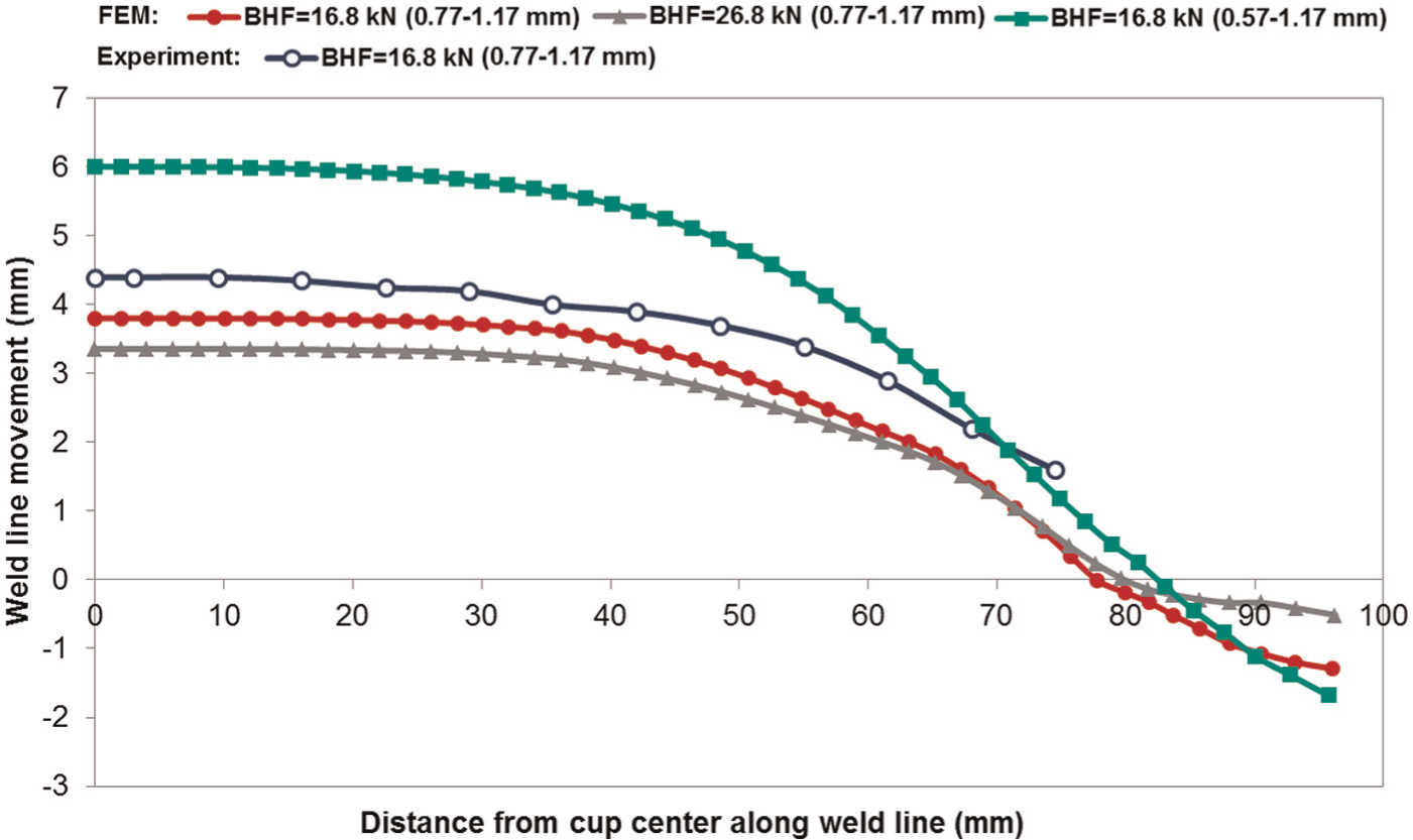
Weld line movement in deep drawn square cups made from TWBs under uniform BHFs obtained by the experiment and the FE model.
According to the promising results for controlling the weld line movement in the strip drawing of a TWB using an appropriate non-uniform BHF, some combinations of BHFs acting on each side of the TWB separately are examined through the FE model to reduce the weld line movement in the square cup drawing as shown in Figure 17. As the BHF over the thinner side is raised from 8.4 to 13.4 kN, a reduction of 74% in the maximum weld line movement is observed. The weld line movement at the flange area also decreases by increasing the BHF on the thinner side. Figure 18 compares the experimental and simulated configurations of the square cup deep drawn from a TWB with the thickness of 0.77 and 1.17 mm using a non-uniform BHF of 8.4 and 13.4 kN.
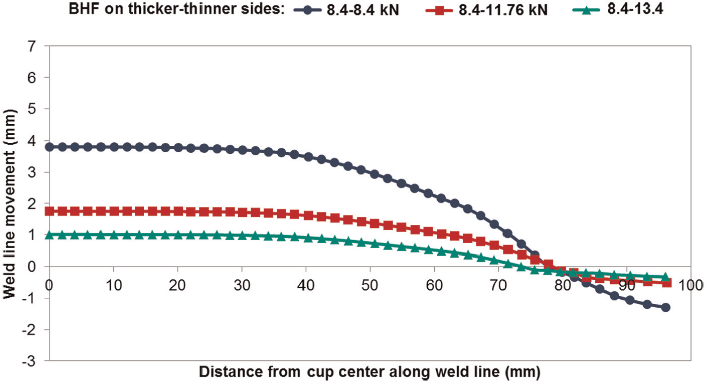
Effect of non-uniform BHF on weld line movement in a deep drawn TWB with the thickness combination of 0.77 and 1.17 mm.
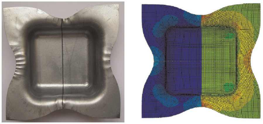
Experimental and simulated configurations of the deep drawn TWB with the thickness combination of 0.77 and 1.17 mm using the non-uniform BHF of 8.4 and 13.4 kN.
Conclusion
The main objective of this study was to restrict the weld line movement using a non-uniform BHF. The proposed analytical model predicts the required BHFs based on Hill’s quadratic yield criterion and by considering the effect of frictional forces and bending–unbending in the die and punch corner radii. The FE models of strip and square cup deep drawing were established using the commercial FE code ABAQUS. It has been shown that the experimental, theoretical, and numerical results are in a reasonable agreement. The following conclusions can be highlighted:
To reduce the weld line movement under the condition of a uniform BHF, higher clamping forces should be applied.
Using an appropriate non-uniform BHF, the weld line movement can be effectively reduced.
Increasing the thickness ratio leads to more weld line movement and hence a further increase in the BHF on the thinner side would be necessary.
For the same die corner radius at both sides, a decrease in the radius leads to the higher BHF ratio. On the other hand, by decreasing the corner radius at the thinner side, the required BHF ratio decreases so that the values lower than unity can be reached.
Footnotes
Appendix 1
Appendix 2
Acknowledgements
The authors would like to thank Mr Hasanniya of Materials Research and Engineering Department of Supplying Auto Parts Company (SAPCO, Tehran, Iran) for the laser-welded blanks.
Declaration of conflicting interests
The authors declare that there is no conflict of interest.
Funding
This research received no specific grant from any funding agency in the public, commercial, or not-for-profit sectors.