
Abstract
Tailor-welded blanks of interstitial free steel are commonly used in complex automotive skin panels. The presence of weld zone, difference in thickness and high anisotropic behaviour affect forming behaviour of tailor-welded blanks significantly. Therefore, incorporation of anisotropy of the sheets and properties of the weld zone in finite element simulations is very important for accurate prediction of springback in bending of tailor-welded blanks. In this study, experimental and finite element simulations of V-bending were carried out on tailor-welded blanks of three thickness combinations, prepared by Nd-YAG laser welding of interstitial free steel sheets of thicknesses 0.8, 1.2 and 1.5 mm. The orientation of the weld line in longitudinally welded blanks was kept at 0°, 45° and 90° with respect to the rolling direction to study the effects of anisotropy on springback in V-bending. The tensile properties of the weld zone in different thickness combinations were determined and incorporated in finite element simulations for prediction of springback. It was observed that springback results were mainly governed by the springback behaviour of the thicker sheet in a particular thickness combination. Weld zone properties affect the springback of tailor-welded blanks more significantly than the anisotropy of the sheets. Accuracy of predicted values of springback in simulations increased when the properties of the weld zone were incorporated in the material model.
Keywords
Introduction
The focus on improving vehicle crashworthiness along with weight reduction for better fuel economy has led to worldwide interest in application of tailor-welded blanks (TWBs) in manufacturing of automotive sheet metal parts. A TWB consists of two or more blanks that have been welded together in a single plane prior to forming. The blanks thus joined by welding can have same or different thickness, mechanical properties and surface coatings. Various issues related to TWBs, such as joining and forming issues, defects, characterization of microstructure, mechanical properties and formability have been studied by a significant number of researchers.1–10 Springback in forming of TWBs is an important issue as it leads to geometrical and dimensional changes in the formed components. Springback, most pronounced in sheet metal bending, is defined as the change in the bend angle due to elastic recovery after the removal of forming loads.
Several researchers have investigated and explored the various issues related to springback behaviour and its minimization in bending of conventional blanks. Behrouzi et al. 11 applied bending theory in an inverse algorithm for springback compensation in V-bending of sheets. Rahmani et al. 12 examined effects of sheet thickness and bending orientation with respect to the rolling direction (RD) on springback in V-bending of steel sheets. It was shown that by increasing bending orientation, yield strength and springback increased. Lajarin and Marcondes 13 statistically analysed the influence of process and tool parameters on the magnitude of springback in U-bending of high-strength steels. Choudhury and Ghomi 14 investigated the effects of punch holding time, type of material and lubrication on minimization of springback in V-bending of aluminium sheets using the Taguchi approach. Apart from providing allowance in die/punch design, compensation for springback can also be accomplished by bottoming the punch or stretch bending the work piece. 15
Springback behaviour in TWBs is more complex as compared to a conventional blank, due to the differences in material properties and/or thickness and the presence of weld zone. Accurate prediction of springback in TWBs in a bending operation is very challenging and also necessary to allow optimum die design incorporating springback compensation as a corrective measure. Chang et al. 16 studied the effect of different punch profile radii on springback in TWBs with weld line oriented in transverse and longitudinal directions in a U-bending process and concluded that springback in transverse welded strips is same as that of unwelded strips, whereas springback decreased in longitudinal welded strips. It was suggested that for accurate prediction of springback, inclusion of weld zone should be addressed in further studies. Seo et al. 17 investigated the effects of punch and die profile radii and blank holding force on springback behaviour of TWBs in a U-draw bending operation. It was observed that springback in both transverse and longitudinally welded strips reduced with an increase in blank holding force. Xu et al. 9 carried out experimental studies on effects of weld orientation and thickness combinations on deformation behaviour of high-strength steel structures using three-point bending tests and demonstrated that TWB structures with weld orientation at 45° to the bending moment have the greatest advantages of different TWB steel sheets. Kim et al. 18 carried out experimental and numerical investigations on springback behaviour of friction stir welded TWBs in cylindrical bending and draw bending and observed that springback of TWBs is significantly affected by the ratio of the yield stresses for a particular thickness combination.
Some researchers have investigated weld zone and its influence on formability. Ciubotariu and Brabie 5 studied the tensile behaviour of TWBs and found that formability is reduced due to increased tensile strength and reduced elongation and work hardening coefficient. It was also emphasized that heat affected zone (HAZ) should be included in the studies of TWBs. Owing to the fact that standard tests cannot be performed to determine mechanical properties of the weld zone due to small size of the weld cross section in TWBs, Rojek et al. 19 presented different methods to determine mechanical properties of the weld zone in TWBs. Khan et al. 8 carried out studies on effect of thickness ratio on weld line displacement in deep drawing of aluminium–steel TWBs in three thickness combinations and found that weld line displacement increases with an increase in the thickness ratio. Vasudevan et al. 20 observed that the Lankford anisotropy parameter (R-value) influences thickness distribution, weld line movement and failure location in forming of TWBs. Asadian-Ardakani et al. 21 examined, theoretically and experimentally, the effects of non-uniform blank holding force on weld line displacement during deep drawing of a square cup. Song and Hua 22 conducted experimental and numerical studies on crack initiation during the Erichsen cupping tests in TWBs of sheets of identical strength but different thicknesses and developed a quantitative relationship between the Erichsen index values and the thickness ratio. Shi et al. 23 presented a modelling method using twofold beams including weld geometry and material properties to simulate the behaviour of weld line under realistic impact loading. The finite element analysis (FEA) of TWBs excluding weld properties and geometry was also conducted to establish the comparison. Similarly, Raymond et al. 24 numerically evaluated the effects of weld zone on forming of TWBs, indicating a number of subtle effects associated with the manner in which the weld is modelled.
The presence of weld zone comprising HAZ and fusion zone is one of the challenging issues in experimental and numerical studies on springback of TWBs. Zadpoor et al. 25 investigated the springback in friction stir TWBs of aluminium sheets of same thicknesses. S-rail benchmark problem was used for simulations for springback prediction with incorporation of mechanical properties of the HAZ and weld nugget. It was shown that incorporation of weld properties in FEA model significantly improves accuracy of springback prediction but adds to the simulation time.
However, no literature has been found on inclusion of weld zone in numerical simulations of V-bending for springback procedure. This work comprises experimental investigations and numerical simulations of springback behaviour in TWBs in V-bending process, with and without inclusion of weld zone properties of three thickness combinations of anisotropic interstitial free (IF) steel sheet having similar mechanical properties.
Experimental procedure in V-bending
Selection of material
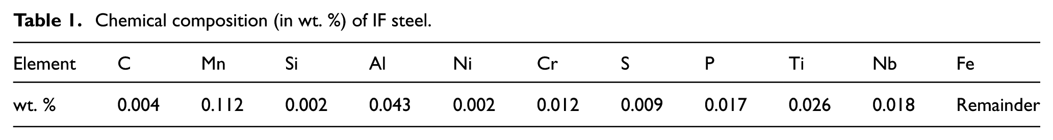
The term ‘interstitial free’ refers to the fact that there are no interstitial solute atoms to strain the iron lattice resulting in steels with low yield strength, high plastic strain ratio and excellent formability. IF steel sheets are manufactured by special processing of ultra-low carbon steel with addition of Ti and Nb. It was selected on the basis of its excellent formability and wide applications in TWBs for manufacturing automotive body panels. In this work, cold-rolled and annealed IF steel sheets of thicknesses 0.8, 1.2 and 1.5 mm have been used to prepare TWBs to study their springback behaviour. These thicknesses were chosen because the most common range of sheet thickness used for automotive sheet metal components is 0.8–1.6 mm. Keeping 0.8 mm sheet thickness common to all the three thickness combinations, the different thickness ratios used are 1.0, 1.50 and 1.875. The chemical composition of IF steel sheets used in this work is given in Table 1.
Chemical composition (in wt. %) of IF steel.
Preparation of TWBs
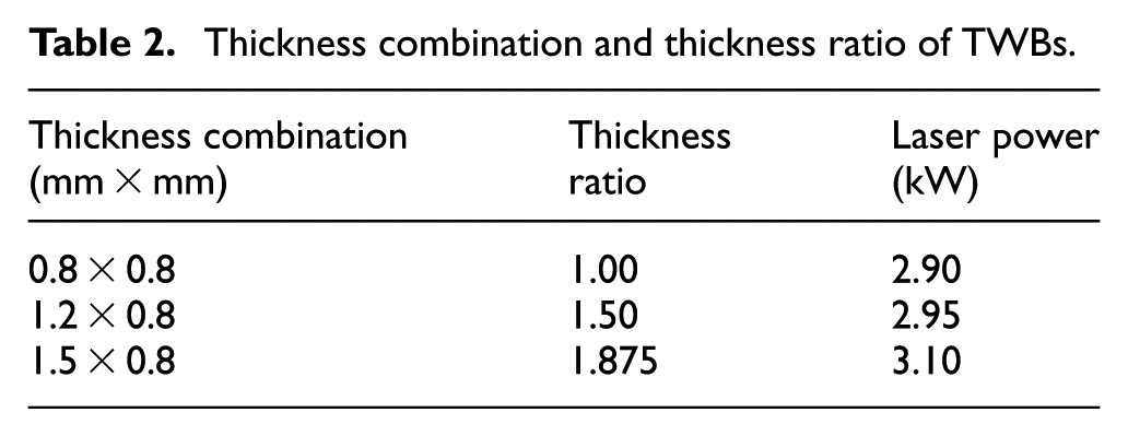
Specimens of IF steel with different thickness combinations, as shown in Table 2, were prepared by laser welding. For laser butt-welding, apart from preparation of proper edges, misalignment and gap between the edges are critical that influence the quality of the weld. The blanks were cut from the sheets by CO2 laser cutting (Trumpf make) at a cutting speed of 1.2 m/min to ensure that edge straightness and burr size are within the acceptable limits for laser welding. The samples were laser welded at a speed range of 4.8–7 m/min in an inert atmosphere of Argon with flow rate of 7–10 L/min using a 4 kW capacity Nd-YAG laser. Higher laser power was used in welding with an increase in thickness ratio. The specimens were taken at different orientations at 0°, 45° and 90° to the RD to study the effect of anisotropy on mechanical properties and springback.
Thickness combination and thickness ratio of TWBs.
Determination of weld zone width
Determination of the weld zone was done on the basis of microstructural study. Specimens from the TWBs, containing the weld region and parent materials, were carefully cut by a diamond abrasive wheel and mounted using Bakelite. The mounted specimens were fine polished and etched with 2% Nital solution (2% nitric acid + 98% methyl alcohol) to observe the microstructure. The microstructure, as shown in Figure 1, clearly reveals the HAZ and fusion zone. The HAZ on either side is characterized by smaller grain size as compared to the parent materials, whereas the fusion zone is observed with coarse and elongated grains. The width of the weld zone was carefully measured at a magnification of 50 × for all the thickness combinations.
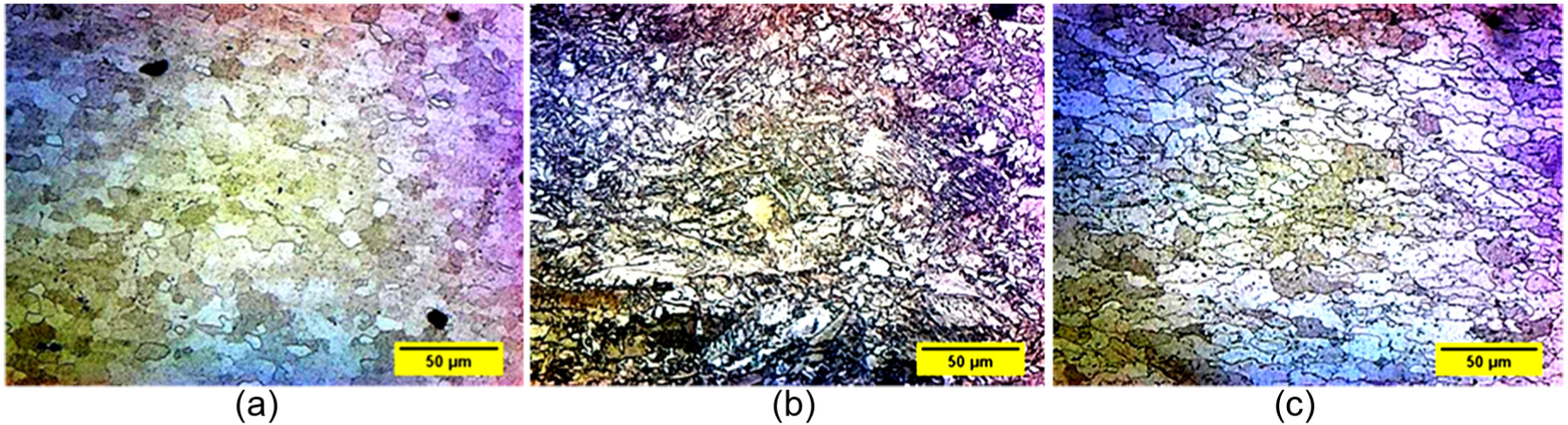
Microstructures showing parent material and fusion zone in TWB: (a) parent material (0.8 mm), (b) fusion zone and (c) parent material (1.2 mm).
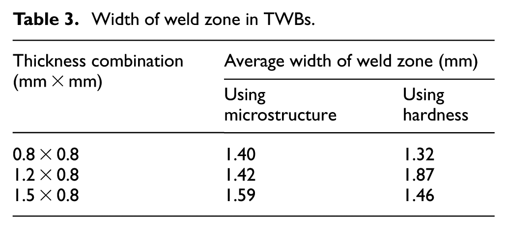
The mounted specimens were also tested for Vickers hardness (VHN) by making a series of micro indentations under a load of 100 g, after a set interval of 0.25 mm across the weld region to determine the width of the weld zone as shown in Figure 2. A comparison of width of the weld zone for different thickness combinations, obtained by microstructural and hardness studies, is given in Table 3.
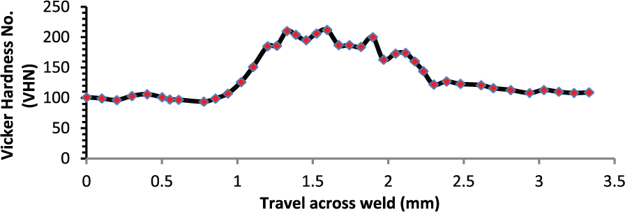
Variation of microhardness across the weld region of TWB with thickness combination of 1.2 mm × 0.8 mm.
Width of weld zone in TWBs.
Tensile properties of parent materials and TWBs
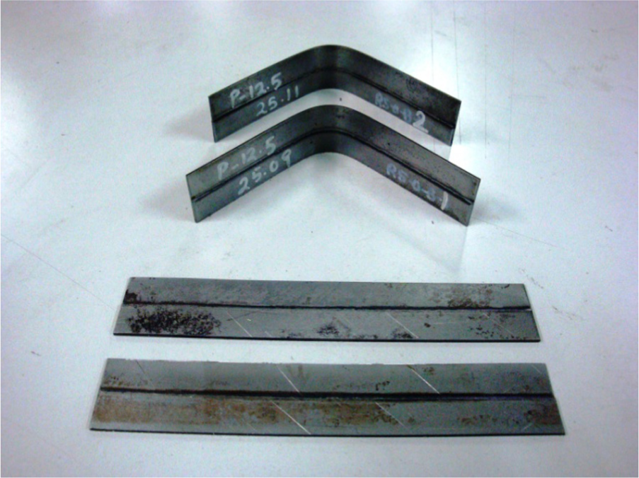
In order to determine the mechanical properties of parent sheets in orientations that are parallel (0°), diagonal (45°) and perpendicular (90°) to the RD, the tensile specimens were prepared as per ASTM-E8M specifications and tested on a 50 kN universal testing machine (UTM) at a constant cross-head speed of 2.5 mm/min. Subsize tensile specimens (as per ASTM-E8M standard) of TWBs of different thickness combinations were also prepared and tested with weld line oriented at 0°, 45° and 90° with respect to the RD. Tested and untested tensile specimens of both IF steel sheets and TWBs are shown in Figure 3(a) and (b). From the load-elongation data, engineering stress–engineering strain curves and true stress–true strain curves have been plotted. As IF steel obeys general power law of strain hardening (σ = Kεn), where σ and ε are true stress and true strain, respectively, the values of strain hardening index (n) and strength coefficient (K) have been determined from log σ − log ε plots considering the data from within the uniform plastic deformation range. The normal anisotropy or the average plastic strain ratio
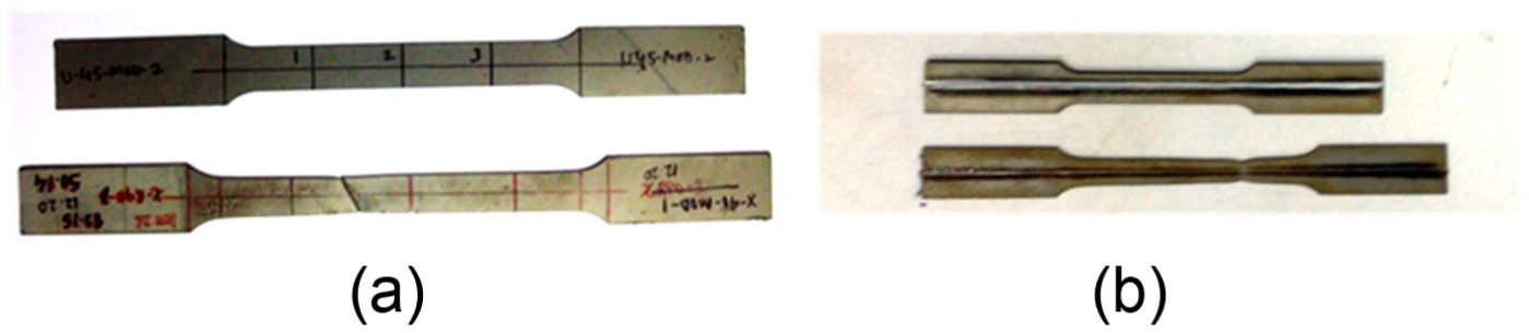
Tested and untested tensile samples of (a) parent material and (b) TWBs.
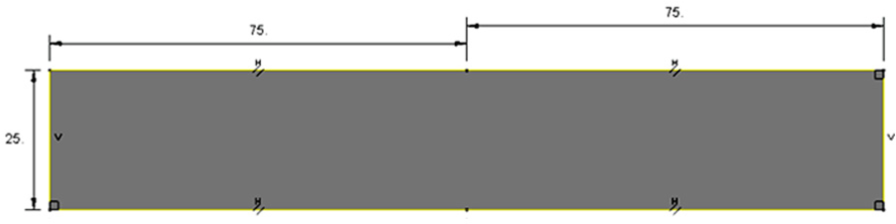
The properties determined from the tensile tests of TWBs (shown in Figure 3(b)) do not reflect the actual properties of the weld zone alone because the width of the specimen is 6 mm, while the actual width of the weld zone is less than 2 mm. Therefore, to determine the tensile properties of the weld zone, specimens with very small width (almost equal to weld zone width) have been prepared by wire cut–electric discharge machining (WEDM). The tested and untested samples of the weld zone are shown in Figure 4(a) and (b).
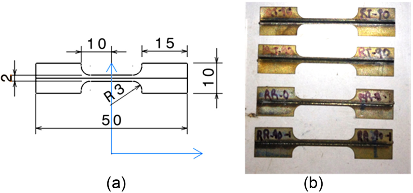
Tensile specimens of weld zone: (a) specimen drawing (dimensions in mm) and (b) samples prepared by WEDM.
Experimental set-up for springback
An experimental set-up has been developed for determination of springback in V-bending. It consists of a V-die with an included angle of 90° and punch (as shown in Figure 5(a)) with profile radius of 15 mm. Different punch-die sets were designed and fabricated for different sheet thicknesses with appropriate clearance provided on the dies. The clearance was kept equal to the sheet thickness in order to prevent any localized compression at the bottom of the die. The dies and punches were prepared from AISI D2 steel using WEDM process. Tools were air hardened and tempered. V-bending experiments were carried out on the 50 kN UTM. The punch shank was secured in the grip mounted on the movable cross head, and the die was fixed to the stationary wedge grip as shown in Figure 5(b).
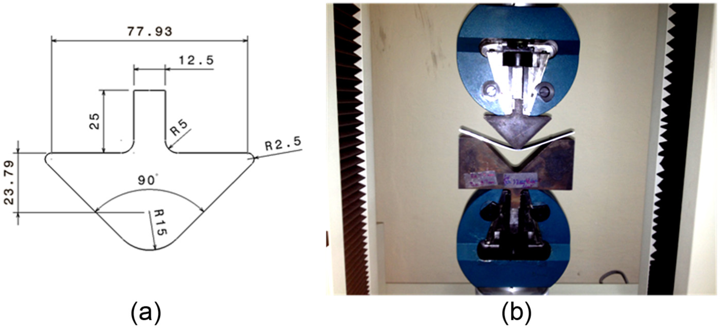
(a) Design of punch (dimensions in mm) and (b) experimental set-up for V-bending.
The bend specimens were cut by WEDM process, with dimensions 150 mm × 25 mm (as shown in Figure 6) to ensure plane strain condition for which the width should be at least 10–15 times the sheet thickness. It was ensured that the weld line was exactly at the centre of the width in case of specimens of TWBs for V-bending. During bending tests, the flat side of TWB specimen was kept towards the punch side, and a filler sheet, whose thickness was equal to the thickness difference in TWBs, was used between the die and the blank to prevent any twisting. However, depending upon the thickness ratio, small twisting is expected in normal bending operations. Higher the thickness ratio, higher may be the twisting due to higher magnitude of unbalanced force, if the shims are not used. A punch speed of 20 mm/min was adopted in all the experiments. The displacement of the punch was kept equal to the die depth during bending experiments and it was controlled precisely by a dedicated software.
Specimens for bending of TWBs.
A vision inspection system with a probe sensor was used to measure the final included angle in the tested bend specimens. Each tested specimen was secured in a magnetic V-block and measured twice for interior included angle using a probe by touching at four points on each arm of the tested specimens. The initial included angle (θ0) was measured on the die.
Modelling and simulations
In this study, all the simulations were performed using ABAQUS software in two steps – loading and unloading. ABAQUS–Explicit solution procedure was adopted for the bending simulations (the loading step) as it can handle nonlinear complicated contact problems with ease in a shorter time. The completed bending simulation model was exported from Explicit to ABAQUS–Implicit to conduct springback simulations. Springback simulations offered lower nonlinearity as the unloading was done by removing the punch and die constraints from the model.
Modelling and meshing
In this study, bending process is treated as a non-linear problem. Generally there are three sources of nonlinearity in the bending problem: material nonlinearity, boundary nonlinearity and geometric nonlinearity. Material nonlinearity occurs due to plastic behaviour of anisotropic sheet metals following the power law of strain hardening in the region of true-stress and true-strain curves. Boundary nonlinearity arises due to change in the boundary conditions as it happens in the bending process. During bending operation, initially sheet metal is placed on the die shoulder so that only the bottom surface of the sheet metal makes a contact with die shoulder. In order to bend the sheet, punch comes in contact with the upper surface of the sheet metal and material deforms plastically till it finally comes in contact with the die contour to conform to the shape of the die. When a contact occurs during a simulation, there is a large and instantaneous change in the response of the model resulting in nonlinearity due to contact boundary conditions. The third source of nonlinearity is related to the changes in the geometry of a model during analysis. In sheet bending, the sheet metal undergoes a large deflection and the bending load does not remain perpendicular to the sheet being bent. The new bending load can be resolved into horizontal and vertical components which results in change in stiffness of the model.
In order to understand the plastic deformation during bending and its effect on springback phenomenon, simulations for bending were carried out for both parent sheets (three different steels) and TWBs (three thickness combinations). Initially, the bending simulations were carried out for parent materials during which the specimens for bending with dimensions 150 mm × 25 mm were modelled (Figure 7) as deformable surfaces defining the top surface of the blank as a homogeneous continuum shell, and the thickness of the shell was assigned as thickness of the sheet.
Blank surface modelled in FEA (dimensions in mm).
The thickness integration by the Simpson rule with 5-point integration (a default value in ABAQUS) was adopted for conventional and TWB specimens. Prediction of springback depends upon the integration scheme and integration points through sheet thickness. 26 Many researchers have shown in their studies that 5 to 7 integration points are optimal and more than that will not affect the accuracy of springback prediction.27,28 Since the amount of springback depends on bending moment which in turn depends on stress distribution in sheet thickness, shell elements require numerical integration of stress and strain through thickness to determine bending moment and the force. 29 The number of integration points directly affects the simulation time, and therefore, the Simpson rule with 5 integration points method was adopted.
The focus of simulation was not to study the stress variation in the punch and die sets, and so these were modelled as analytical rigid surfaces as shown in Figure 8. Moreover, analytical rigid surfaces do not require meshing and the modelling technique is less time-consuming. The punch was modelled to have a profile radius of 15 mm and dies with corresponding profile radius and clearances. To prevent any localized compression, the clearance was kept equal to the sheet thickness. All the tools were modelled using ABAQUS CAE interface and were assembled as shown in Figure 8.
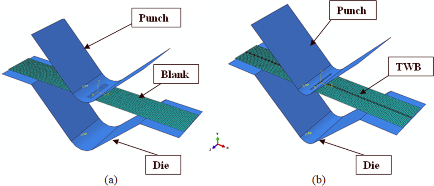
Assembly of tools for bending simulation: (a) conventional blank and (b) TWB.
The specimens of TWB for bending simulations were modelled containing three different regions, that is, two parent materials with different thickness combinations and a weld zone as shown in Figure 9. The top surface of the TWB was first modelled and then the respective thicknesses were assigned to the regions of the two parent materials. The shell thickness in the weld zone was taken to be average of the thicker and the thinner sheets. The mesh size in the weld zone was kept finer compared to parent regions for better results. The mesh size was arrived on the basis of the maximum von Mises stress in the deformed region, that is, the mesh was refined until the stress in the specific region does not change significantly (<1.8%). However, if the mesh is too dense, it requires a large amount of computer memory and long run time.
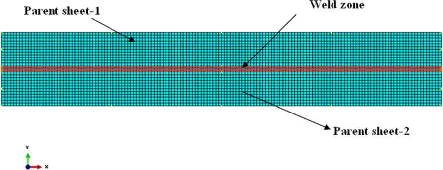
A TWB meshed with continuum shell elements.
The punch and die were modelled as analytical rigid shell, whereas the blank as deformable shell planar with S4R shell elements. The S4R shell element is a four-node thin shell element with reduced integration, hourglass control and finite member strains. The number of elements, nodes and variables used in the finite element (FE) simulation model for simulation of V-bending of conventional blank and TWB are given in Table 4.
Details of blank mesh used in FE simulations.
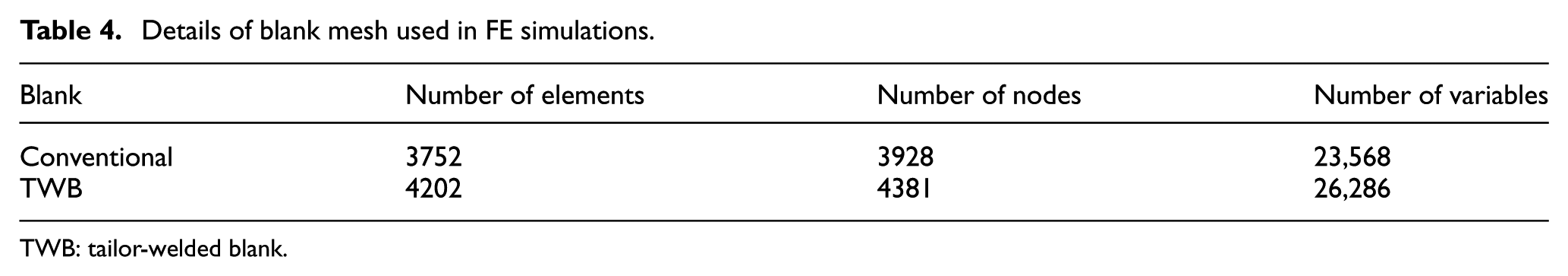
TWB: tailor-welded blank.
To compute the dynamic response of analytical rigid die and punch, a point mass was assigned to the reference point on these rigid bodies. In order to enhance accuracy and efficiency, quasi-static analysis demands that the application of bending load be as smooth as possible. Sudden jerky load application creates stress waves in the blank inducing noisy and inaccurate solution. Load application in a gradual manner requires that the acceleration changes by only a small amount from one increment to the other. This results in the gradual change in velocity and displacement. The explicit method has an inbuilt amplitude curve that creates smooth loading amplitude which was assigned to the reference point on the punch. A typical bending simulation is shown in Figure 10.
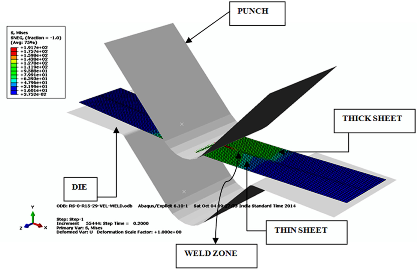
Simulation of V-bending of TWBs.
Material model
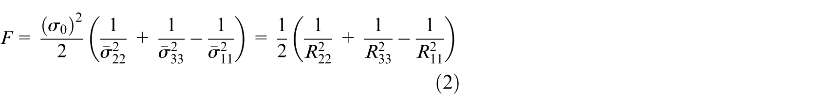
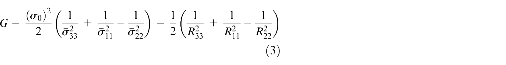
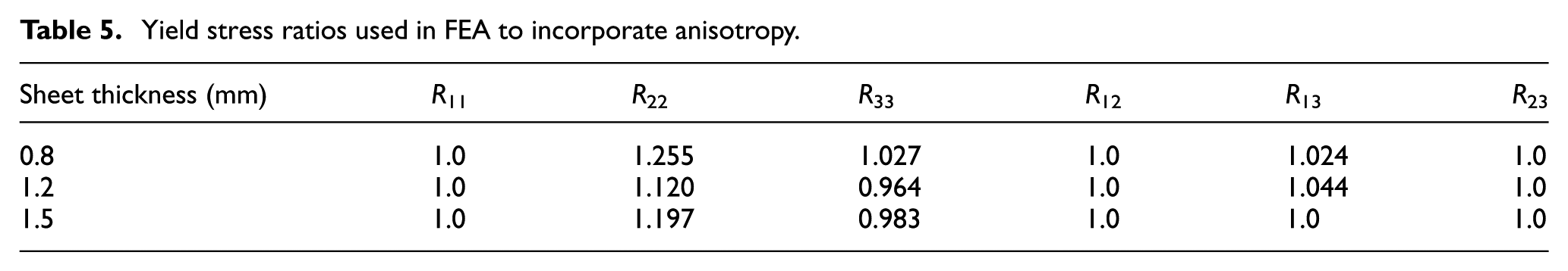
Hill’s plasticity model, also known as Hill’s yield potential which is an extension of the Mises yield function for anisotropic materials, has been used in FE modelling to incorporate anisotropy of sheets 30 and is expressed in terms of rectangular cartesian stress components as given below

where
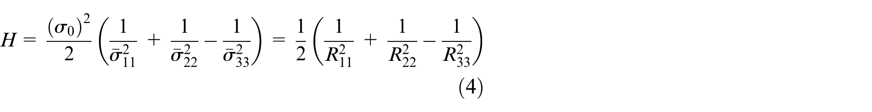


where each

where

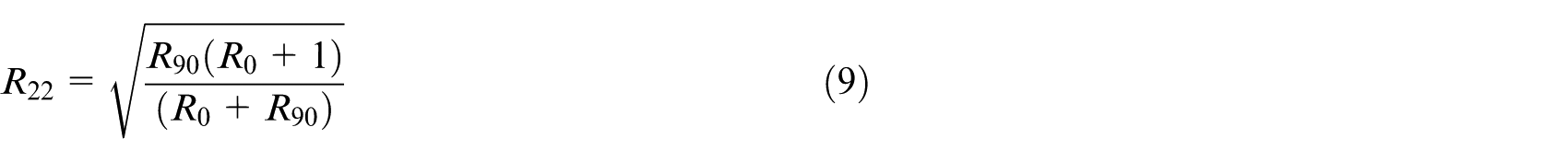
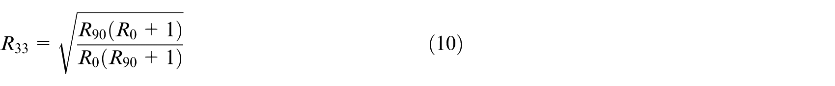
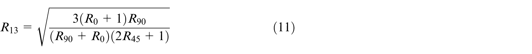
where
Yield stress ratios used in FEA to incorporate anisotropy.
Contact and boundary conditions in bending simulations
A variety of engineering problems require contact to be defined between two or more parts. Friction between the two surfaces causes the shear forces that resist the sliding of the parts in contact. The aim of contact definition is to determine the surfaces in contact to evaluate the contact pressures generated. In FEA, contact definitions are a special class of discontinuous constraint (activates only when two surfaces are in contact) which permits the forces to be transmitted from one part to another. When surfaces are in contact, Coulomb’s law of friction (τ = µp) is a common approach used to define the interaction at room temperature. This equation gives limiting frictional shear stress, therefore the contacting surfaces will not slide until the shear stress across the interface equals the limiting frictional shear stress (τ). In the bending simulations, the die and punch surfaces were defined as master surfaces and the deformable blank as slave surface. Two contact properties with automatic controls were defined with friction formulation as penalty contact by assigning coefficient of friction as 0.125 and 0.05 to blank-die and blank-punch interfaces, respectively.32–34 The die was assigned a boundary condition of ‘Encastre’ (zero displacement and rotation about x, y, z) and the punch was given a pre-determined displacement equal to depth of the die. Different stages in simulations of V-bending of samples of parent sheets and TWBs are illustrated in Figure 11. In the final stage of bending simulation, the bend radius is equal to the punch radius and the bend angle becomes equal to the included angle of the die.
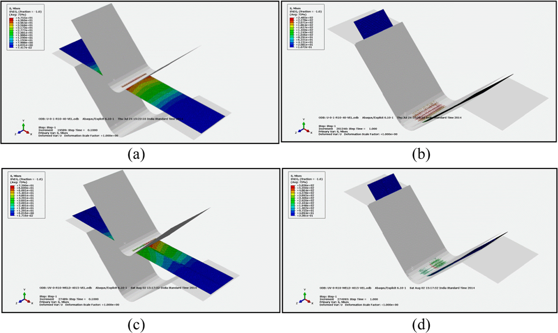
Initial and final stages in FE simulations of V-bending: (a and b) unwelded sheet and (c and d) longitudinally welded sheet.
Springback simulations
The simulations for springback in V-bending for conventional blank and TWBs were performed by removing the constraints such as die and punch, and therefore, the procedure adopted for simulations was static-general (ABAQUS standard) with nonlinearity occurring due to geometry only. This method utilizes Newton–Raphson method to determine the solution for nonlinear problems. This method breaks the simulation into a number of load increments and finds the approximate equilibrium configuration at the end of each load increment. As a result of this, several iterations were made to determine an acceptable solution to a given load increment. After removing all the constraints in the model, the blank was assigned initial state of previous bent data file containing history of loading. A central node in the blank was assigned a zero velocity so that it remains stationary. For springback measurement, node coordinates were captured from the loaded and unloaded frames. The captured coordinates of both the frames were plotted using CAE interface in ABAQUS and the difference between the two gives the change in the included angle after the load is released.
To investigate the effects of weld zone on springback results, TWBs were modelled with and without the weld zone. The change in bend angle due to springback can be obtained in simulations as shown in Figure 12.
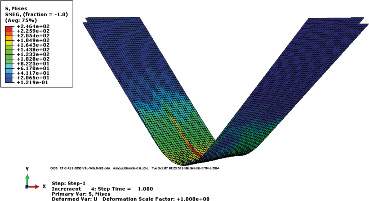
FE simulation of V-bending showing springback in TWBs.
Results and discussion
Tensile properties of parent material
The results of the tensile tests on the specimens of IF steel sheet of three different thicknesses in different orientations are summarized in Table 6. The average values of yield strength (0.2% offset) and ultimate tensile strength (UTS) are approximately 120 and 255 MPa, respectively. The yield strength of the specimens oriented at 45° to the RD has been found to be the highest, followed by the specimens oriented at 90° and 0°, respectively. The same trend has been observed in the values of UTS as well. The ratio of UTS to yield strength is in the range of 1.8–2.5. The material has excellent ductility as indicated by high percentage elongation (>40%) in all the cases. The strain hardening coefficient (n) and strength coefficient (K) in the power law of strain hardening are also given in the table.
Tensile properties of IF steel.
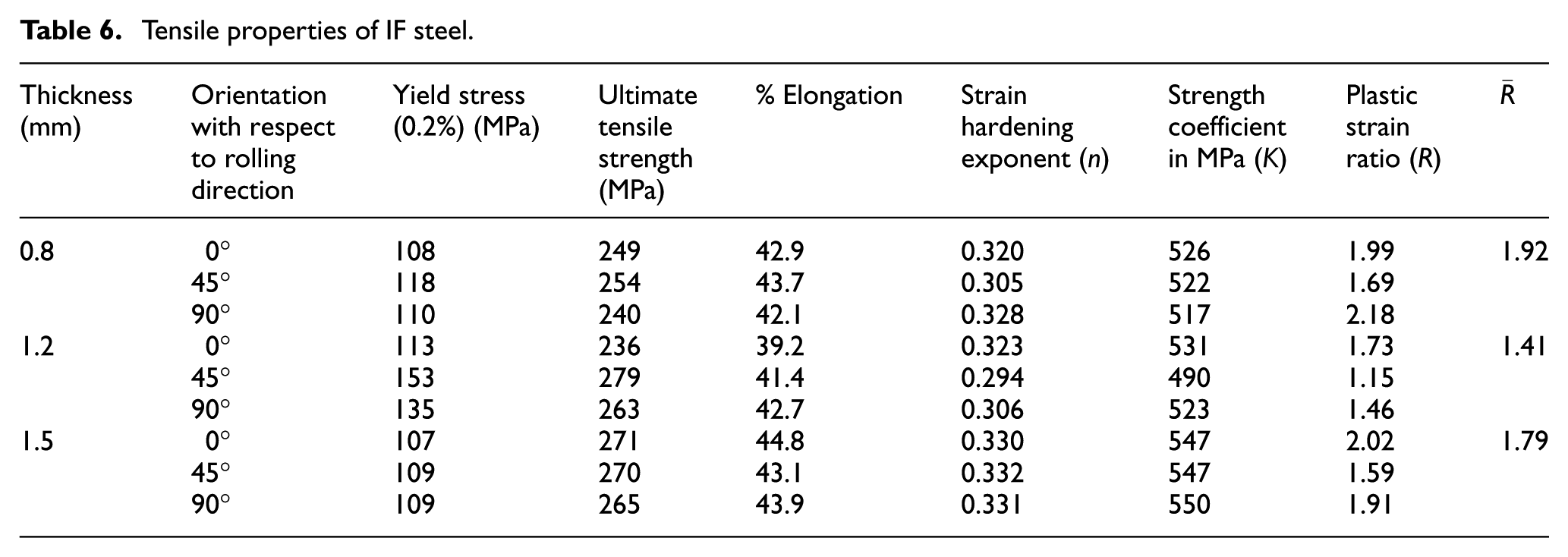
The sheets have been found to be highly anisotropic from the values of plastic strain ratio (R). The plastic strain ratio of IF steel sheets has been found to be maximum for specimens oriented at 90° to the RD and minimum for specimens oriented at 45° to the RD. The average plastic strain ratios
Tensile properties of TWBs and weld zone
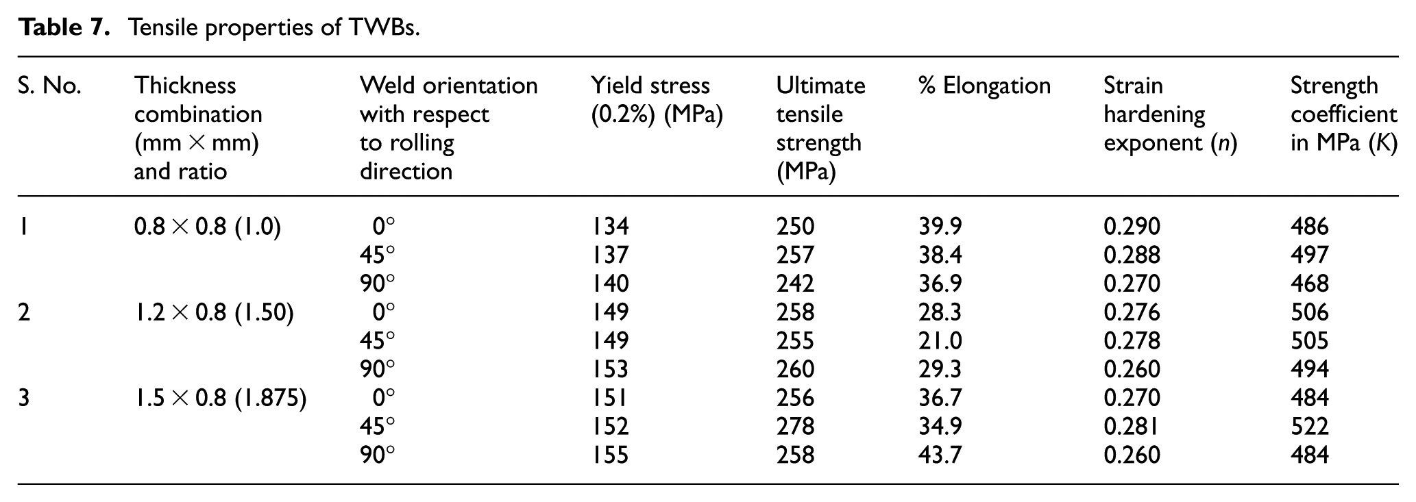
The tensile properties of the tested specimens welded in longitudinal direction are summarized in Table 7. It has been observed that the yield strength of TWBs is generally higher than that of parent sheets and ductility is lower. This could be attributed to finer grains in the weld region and HAZ when compared to the parent materials. The weld zone has much higher yield stress, UTS and strength coefficient but lower elongation and strain hardening exponent than the parent sheets. Due to this, weld zone influences the overall mechanical properties and the springback behaviour of the composite blank significantly, which is clearly reflected in the results. In any given thickness combination, the flow stress of TWB is higher than the flow stress of corresponding parent sheets for a constant strain. Hence, elastic recovery is also higher in the case of TWBs.
Tensile properties of TWBs.
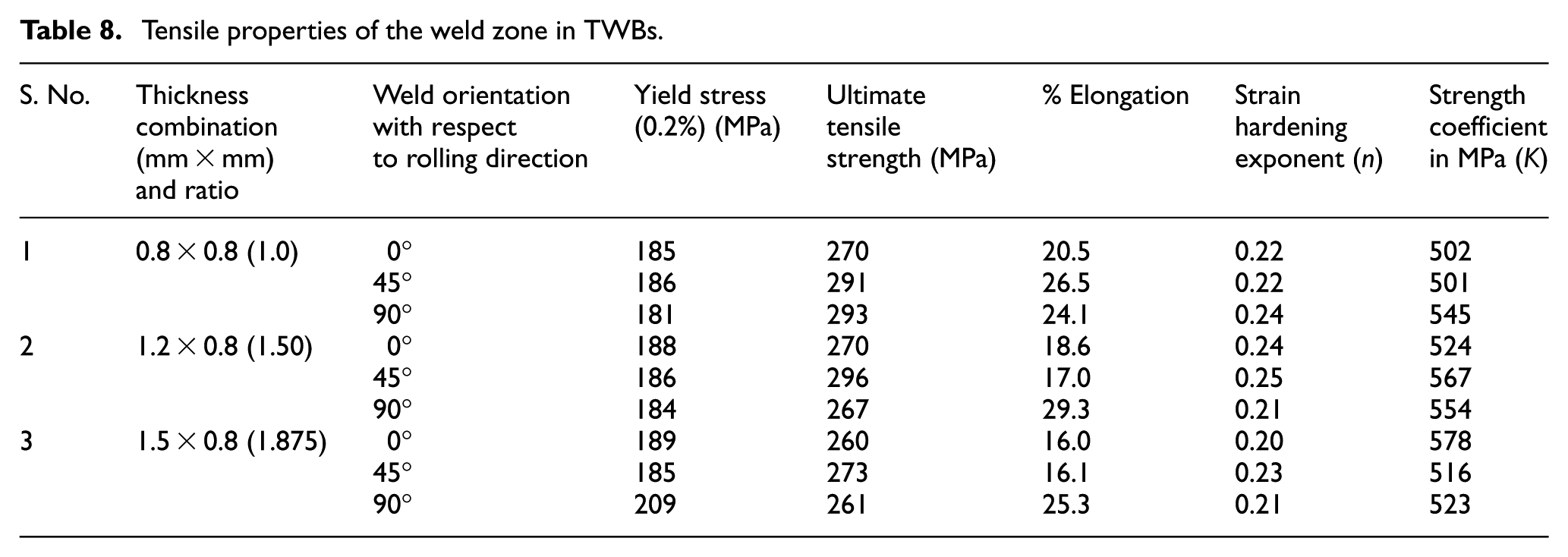
The tensile properties of the weld zone, determined using specimens of width almost equal to the width of the weld zone are given in Table 8. The effect of the thickness ratio on yield strength and ductility can be observed in the weld properties. As the thickness ratio increases, the average yield strength increases and percentage elongation decreases. A substantial decrease of about 31% in the values of strain hardening exponent of 0.8 mm thick sheet is observed along the RD when compared with that of weld zone of 0.8 mm × 0.8 mm thickness combination. Yield strength values of the weld zone along the RD are approximately 42% higher than the values of parent material.
Tensile properties of the weld zone in TWBs.
The comparison of tensile properties of the weld zone in TWBs and the parent material, as shown in Figures 13–15, confirms that the weld zone is mainly responsible for the increased tensile strength and reduced ductility and strain hardening ability of TWBs. This results in reduced formability of TWBs. It clearly indicates that inclusion of the tensile properties of the weld zone is necessary for accurate prediction of the springback in bending by numerical simulations.
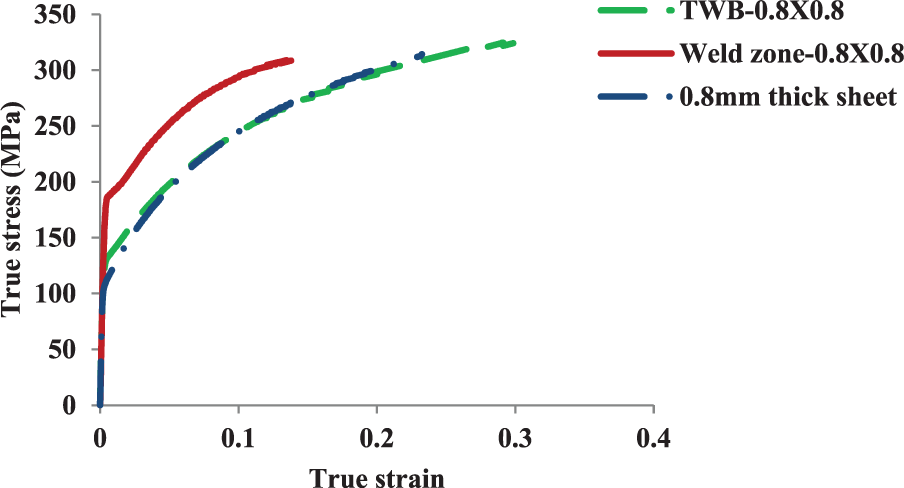
True stress–true strain plots of IF steel sheet of 0.8 mm thickness, TWB (0.8 mm × 0.8 mm) and weld zone (0.8 mm × 0.8 mm) tested along RD.
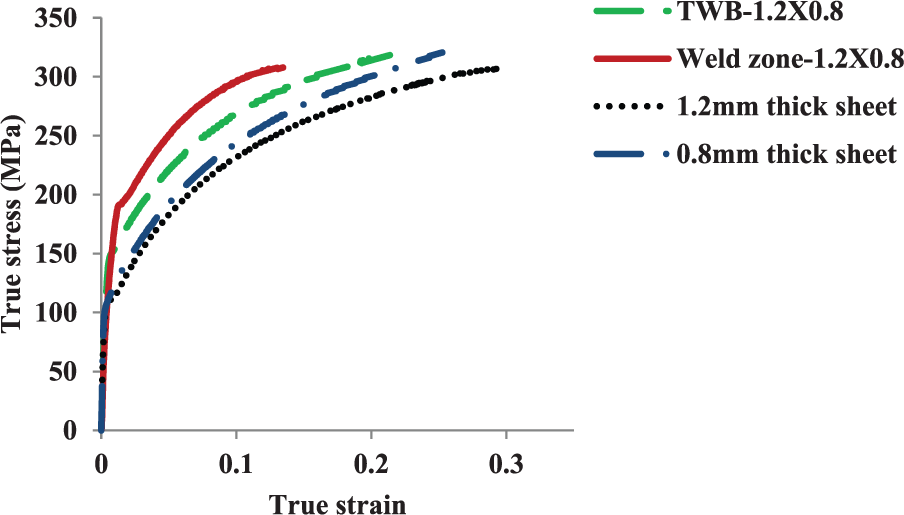
True stress–true strain plots of IF steel sheets of 0.8 and 1.2 mm thicknesses, TWB (1.2 mm × 0.8 mm) and weld zone (1.2 mm × 0.8 mm) tested along RD.
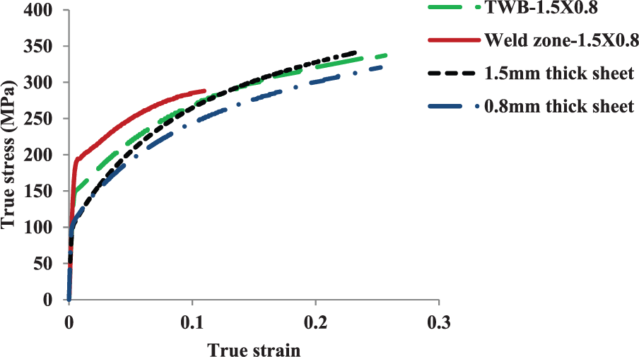
True stress–true strain plots of IF steel sheets of 0.8 and 1.5 mm thicknesses, TWB (1.5 mm × 0.8 mm) and weld zone (1.5 mm × 0.8 mm) tested along RD.
Springback in V-bending
Effect of anisotropy
The springback results obtained from the experiments and simulations of IF steel sheets are summarized in Table 9.
Springback in V-bending of IF steel sheets of different thicknesses.
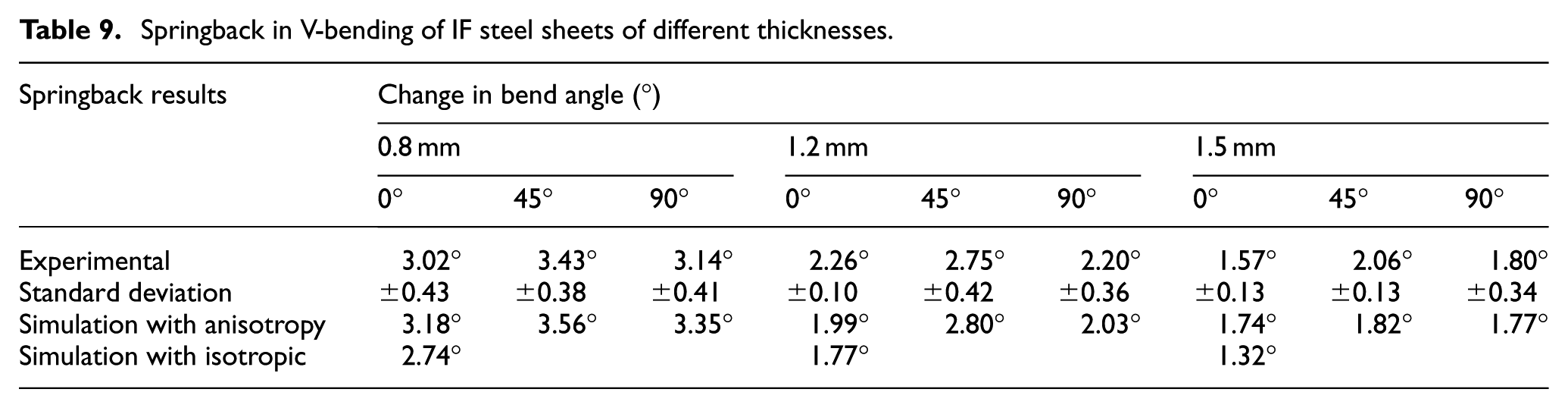
Although, IF steel sheets are highly anisotropic, results of the bending experiments of specimens oriented at 0°, 45° and 90° with respect to the RD show marginal effect of anisotropy and the same trend of results were predicted in simulations by considering anisotropy in the material model. The springback values obtained from experiments and numerical simulations for specimens with different orientations with respect to the RD are shown in Figure 16. It is observed that slightly higher springback is observed in the specimens oriented at 45° to the RD for all the sheet thicknesses and the same trend is observed in springback results predicted by the simulation. This may be attributed to higher yield strength and lower plastic strain ratio in the specimens oriented at 45° to the RD. The springback predicted by numerical simulations considering the material to be isotropic fall significantly below the experimental data in all the sheet thicknesses. The deviation between experimental results and results predicted from simulations without considering anisotropy decreases as the sheet thickness increases. This shows effect of anisotropy is more pronounced in the case of thinner sheets.
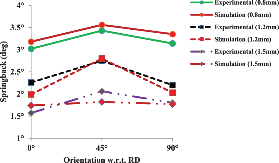
Effect of specimen orientation on springback of IF steel sheets of different thicknesses.
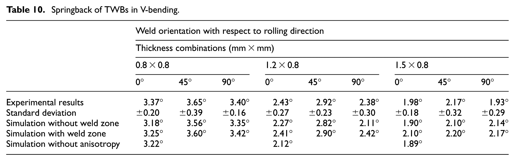
The springback results for TWBs obtained from bending experiments are given in Table 10 and are compared with results obtained from simulations. Most of the results followed the same trend as in the case of the parent materials, that is, springback is marginally higher when the weld line is oriented at 45° to the RD than at 0° and 90°. The comparison of variation of springback in V-bending of TWBs at different orientations of weld line with respect to the RD, obtained from experiments and simulations, are shown in Figures 17–19 for different thickness combinations. Higher springback is observed in thickness combination of 0.8 mm × 0.8 mm, followed by 1.2 mm × 0.8 mm and least in 1.5 mm × 0.8 mm combination. In the case of TWBs with combination of 0.8 mm × 0.8 mm, the springback values predicted by numerical simulations, assuming sheets to be isotropic, are significantly lower than the experimental results. Furthermore, as the thickness ratio increases, the deviation observed between experimental and simulation results without incorporation of anisotropy decreases. This shows that with an increase in the thickness ratio, the effect of anisotropy diminishes. However, in most of the cases, the predicted values of springback agreed more closely with experimental results when anisotropy is incorporated in the material model.
Springback of TWBs in V-bending.
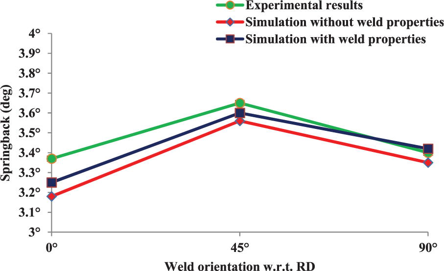
Effect of weld orientation on springback of TWB specimen with 0.8 mm × 0.8 mm thickness combination.
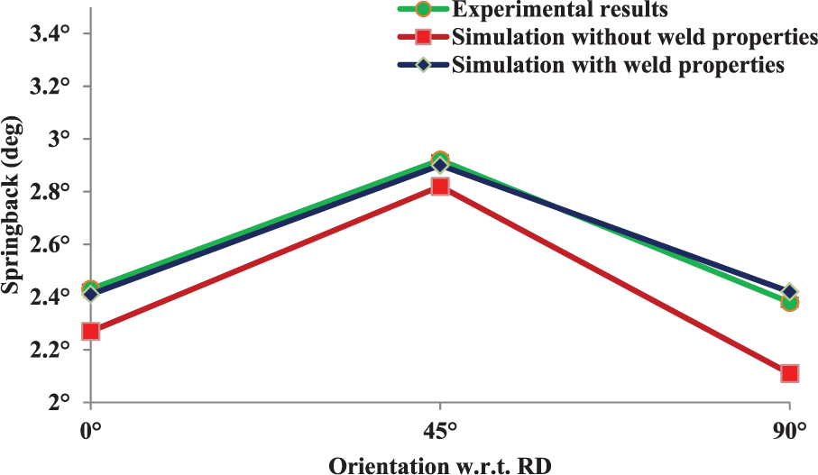
Effect of weld orientation on springback of TWB specimen with 1.2 mm × 0.8 mm thickness combination.
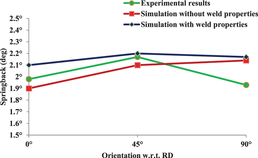
Effect of weld orientation on springback of TWB specimen with 1.5 mm × 0.8 mm thickness combination.
Effect of weld zone
In Table 10, the results of springback predictions with and without incorporating weld zone properties are also compared with experimental data. The weld properties determined from uniaxial tension tests are incorporated in the material model in FE simulations. On comparing the springback of 0.8 mm thick parent sheet with that of TWBs with thickness combination of 0.8 mm × 0.8 mm, it is observed that springback is slightly higher in TWBs which may be attributed to the microstructural changes in the weld zone. Moreover, simulation results with incorporation of the weld zone properties agree more closely with the experimental results as compared to the simulation results without incorporation of the weld region.
Effect of thickness ratio on springback
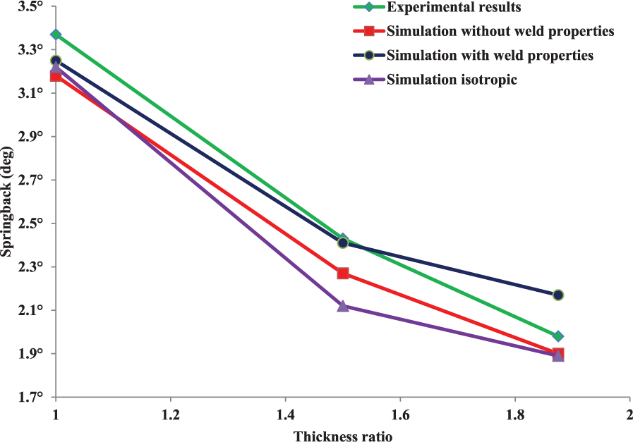
To determine the effect of thickness ratio on springback, three thickness ratios, that is, 1.0, 1.50 and 1.875, are investigated experimentally and numerically. As the thickness ratio increases, springback decreases. It is also observed that there is a minor increase in the springback values for the specimens with thickness ratio of 1.0, when compared to the springback of 0.8 mm thick unwelded parent sheets. This may be attributed to the significantly higher yield strength of the weld zone than the parent sheets.
For the other two thickness ratios, that is, 1.50 and 1.875, it was expected that the springback of TWBs would lie between the springback values of the unwelded parent sheets, but it is observed that the springback of TWB samples is closer to the springback of the thicker sheet in a particular thickness combination. The same trend is shown by springback results predicted by the simulations and illustrated in Figure 20. However, it can be concluded that springback of TWBs is governed by the difference in thickness as well as properties of the parent sheets and the weld zone.
Effect of thickness ratio on springback of TWB specimens in V-bending.
Conclusions
In this work, experimental and numerical investigations were carried out to characterize the springback behaviour of TWBs of IF steel in V-bending with three thickness combinations. On the basis of the observations, the following conclusions are drawn.
The tensile properties of the weld zone were determined from the specimens of width almost equal to the width of weld zone and were incorporated in the material model in FE simulations for prediction of springback of TWBs of IF steel sheets in V-bending.
Although IF steel sheets are highly anisotropic, springback measurements from the bending experiments on TWB specimens with weld line oriented at 0°, 45° and 90° with respect to the RD show marginal effect of anisotropy, and the same trend has been predicted in simulations by considering anisotropy in the material model.
Predicted values of springback of TWB specimens from FE simulations in which the weld zone properties were incorporated agreed more closely with the experimental results as compared to the simulation results in which weld zone properties were not incorporated.
Springback in TWBs with similar thickness combination of 0.8 mm × 0.8 mm has been found to be slightly higher than the springback of 0.8 mm thick unwelded parent sheets. This may be attributed to the higher yield strength and the finer grains of the weld zone. As the thickness ratio increases, springback decreases. In the case of dissimilar thickness combinations, that is, 1.2 mm × 0.8 mm and 1.5 mm × 0.8 mm, springback of TWBs is closer to the springback of the thicker sheets.
Footnotes
Declaration of conflicting interests
The author(s) declared no potential conflicts of interest with respect to the research, authorship and/or publication of this article.
Funding
The author(s) received no financial support for the research, authorship and/or publication of this article.