
Abstract
This paper aims at analyzing the deformation behavior of tailor welded blanks (TWBs), manufactured by laser beam welding (LBW) and gas tungsten arc welding (GTAW), through the deep drawing process. Dissimilar and similar steels with different thicknesses were used in the production of tailor welded blanks. The Nd: YAG laser welding method with nitrogen (N2) as the shielding gas was used to join TWBs. The effects of some significant process factors, namely welding speed, blank holder forces (BHF), material properties of base metals, dry/lubricated condition and laser spot size was experimentally investigated on the weld line movement and drawing depth. Results indicated that using LBW with optimum parameters for the production of dissimilar TWBs caused the control of failure in the weaker base metal. Results showed that the sound welds were produced in similar TWBs with a thickness ratio of 2 when using GTAW, but the weld quality was poor when using LBW. Moreover, it is observed that the critical stresses were taken place outside of the weld zone and rupture due to the high heat input of laser and metallurgical changes of the base metal that occur in the pre-softening zone. In addition, the weld line movement occurred as a result of plastic strain change of the weld joint that caused failure-prone zone creation as well as the adverse wrinkling.
Keywords
Introduction
Today, the industry’s demand for targeted structures and new materials with special properties has improved dramatically to improve efficiency, reduce weight and production costs. Therefore, the transportation industry such as automotive and airplane industries try to use light metals and alloys,1–3 nanomaterials,4,5 composites,6,7 tailor-welded blank (TWB),8,9 etc. TWBs are manufactured and integrated of two or more sheet metals by different welding methods before any forming process in the single plane. 10 The sheets can have different mechanical and geometric properties, such as strength, thickness, surface conditions, and so on. 11 Different properties and features are provided in the TWB for different loading conditions in one blank so that thicker sheets and materials with higher strength or coated steels can be placed in critical parts of the blank to increase the stiffness or corrosion resistance of the final body panel.12–17 Weight saving is the key approach for reducing fuel consumption and preventing detrimental effects on the environment which is achievable by TWBs.14,18–20 Using TWBs reduces the number of forming processes and therefore reduces the final cost of the product. It was reported that 30 to 50 percentage of the purchased sheets turn into scrap. These scraps can be reused in TWBs which makes this technology more and more attractive for industrial applications.13,21 Therefore, the two main features and advantages of the TWB sheets are: (a) Constructing unlimited dimensional blanks with various mechanical properties and geometric features and choosing different properties and features for different loading conditions in one blank to reduce costs and lightening weight, (b) Lowering the cost, dimensional tolerance and waste, by applying the formability process after welding and for the integrated instead of doing the formability for each part individually before welding. The history of the first use of TWB sheets back to 1992, which was used in the USA automotive industry to integrate parts, reduce cost and weight, increase the precision, quality of parts and stiffness. 10
The most widely used metal in the production of TWBs are steel alloys and different welding methods were used in the previous studies to investigate the formability of TWBs. Many parameters are involved in producing and forming of TWBs including geometrical parameters, welding and forming process parameters. A lot of research has been done to investigate each of these parameters, which we will discuss below. Habibi et al. 22 experimentally studied the formability of the St14 TWB sheet manufactured by friction stir welding (FSW) through the uniaxial tensile test and forming limit diagram (FLD). They concluded that the presence of the weld region decreases the ductility of TWB compared to the base metals and the formability decrease by the thickness ratio increasing of the TWBs. Mypati et al. 23 used fly-ash and Al-12%Si as diffusive coating materials in the FSW of AISI 304 steel welded with AA 6061 to improve the weld quality. The results showed that formation of intermetallic reaction layer affected the weld quality. Parente et al. 24 studied the formability of aluminum tailor welded blanks which were produced by the FSW process. The TWBs consist of AA5182 and AA6061 aluminum alloy sheets which were welded with different weld line orientations. Their results indicated that decreasing the weld line orientation angle will increase the values for FLD and formability of aluminum TWBs. The experimental and theoretical results Xiang and Ying-ping 25 confirmed that the St12 TWBs with different thickness had less formability than the base sheet. In their investigation, based on the elastoplastic mechanical properties of the weld and heat affected zone metals obtained by a nanoindentation test, a theoretical calculation model was established for the FLD of TWBs on the basis of plastic constitutive relations and Hosford yield criteria. 25 Safdarian et al. 26 investigated the role of thickness ratio on the formability of the ST12 TWB sheet produced by laser welding. Their results showed that the level of FLD decreased by the increase of thickness ratio. The effect of strength ratio was also studied on the formability and FLD of steel TWBs by Safdarian.27,28 Three different groups of TWBs with different base metals of AISI340, St12, and St14 were welded using CO2 laser welding method. The results indicated that the FLD level decreased by the strength ratio increase of TWBs. Safdarian et al. 29 investigated the effect of Nd:YAG laser welding parameters on the weld quality and mechanical properties of TWBs. They suggested the optimum welding parameters to join steel TWBs. Casalino et al. 30 evaluated the fiber laser/TIG weldability of AISI 304 and AISI 410 dissimilar weld. Also, the effects of welding parameters, such as laser line energy and arc current, were assessed. Finally, the results showed the good and easy weldability of dissimilar austenitic and martensitic stainless steels in annealed condition by fiber laser coupled with an electric arc. Wen-yu et al. 31 investigated the role of friction coefficient on the deep drawing of AA6111 at elevated temperatures based on the three conditions using the finite element analysis and the experimental approach. Results indicate that the friction coefficient and lubrication position significantly influence the minimum thickness, the thickness deviation and the failure mode of the formed parts. Xue et al. 32 assessed the influence of pulsed Nd: YAG laser beam welding parameters such as laser beam power, pulse duration, overlap, spot diameter, pulse type, and welding velocity on penetration and microstructure characterization of DP1000 butt joint. They concluded that weld quality can be influenced by several process factors, such as laser beam power, pulse duration, overlap, spot diameter, pulse type, and welding velocity.
Sharma and Molian 33 investigated the weldability of ND: YAG disk laser welding of various combinations of advanced high strength steels with 1 to 2 mm thicknesses. Weldability was defined in terms of penetration, weld profile, weld defects, microhardness, and melting efficiency. Microhardness measurements indicated a substantial increase in hardness in the weld zones, attesting the superiority of laser welding and analyses revealed that the typical melting efficiency is on the order of 50% to 70% for full penetration welding.
In order to decrease the weld line movement, two different ways were proposed in the literature which is the application of different forces on different materials and the use of draw bead.19,21,34 Korouyeh et al. 35 investigated the weld line movement of TWBs in the Hecker formability test using experimental and numerical methods. LBW and GTAW are the most commonly used coupling techniques in the automotive industry. The most important advantages of LBW include small spot size, high energy concentration, high production speed, and low distortion and structural changes in welded samples.13,15,16,21,36,37 Safdarian 38 investigated the effect of GTAW parameters such as welding current, shielding gas pressure, welding speed and diameter of filler material on the formability of aluminum TWBs. His results indicated that shielding gas pressure and welding speed have the greatest impact on the formability of aluminum TWBs. Salerno et al. 39 used experimental and numerical methods to investigate the focused-tungsten inert gas welding process of Inconel 718 thick plates.
In the present study, two methods of LBW and GTAW have been used to examine the various welding parameters on the welding quality, the weld line movement and the degree of formability in deep drawing operations for Steel TWBs. Furthermore, the deep drawing process was carried out along with controlling the input parameters to minimize the weld line displacement as well as to maximize the forming depth. In the LBW, four welding parameters (spot size, welding speed, material, and thickness ratio) were studied and in TWBs processed by the GTAW, two deep drawing parameters (blank holding force and lubricant), material and thickness ratio were investigated. This novel comparison could be employed by automobile companies to reduce the weight, cost and safety factor of their steel products while increasing their mechanical strength and surface quality.
Materials characterization
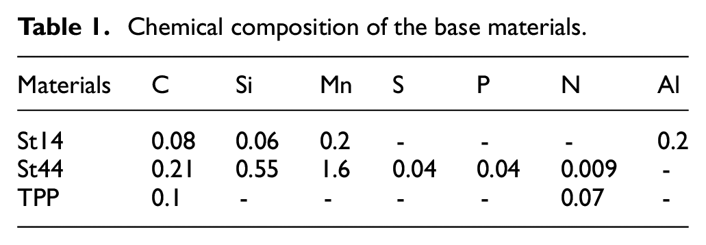
In this study, low carbon steels (St14, St44, and TPP) sheets were used in wrought conditions as the base materials. Chemical compositions of base materials are presented in Table 1. The mechanical properties of the base metals were investigated via the uniaxial tensile test. For this purpose, standard tensile specimens with 1 mm thickness were prepared according to ASTM-EM8-04 using a four-axial CNC cutting machine at Iran Khodro Automotive Company. The uniaxial tensile tests were done with the speed of 2 mm/min for all the specimens at room temperature. Figure 1 shows the stress-strain curve of the uniaxial tensile test.
Chemical composition of the base materials.
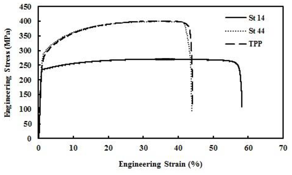
Engineering stress-strain curves of base materials at the rolling direction.
Welding methods
Two different welding methods of LBW and GTAW processes were used to prepare the TWBs.
Laser beam welding process
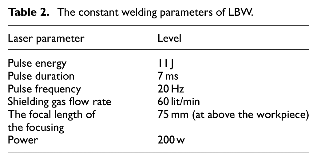
In the first group, the sheets were welded using a pulsed Nd: YAG laser (IQL-10 model) with an average power of 200W. A set of rotameter flow meters was used to measure the shielding gas flow rate. The coaxial shielding gas nozzle with a 5 mm diameter was positioned at 2 mm distance from the work-piece surface. The ultra-high purity argon gas was used as the shielding gas with a flow rate of 14.1 Liter per minute (L/min) on the top surfaces of the blanks. The focus of the beam was set to be on the top surface of the blanks, which is shown in Figure 2(a) and (c). Figure 2(a) shows the fixture that was used to fix the blanks in the welding process. blanks having a diameter of 200 mm were used in both LBW and GTAW processes. A four-axis CNC punching machine (Trumatic 160) was used to cut the blanks. The boundary surfaces of the sheets were polished using 600 grit sandpapers. Then acetone was used to remove contaminants. The CO2 and O2 gases were then added to the argon gas. All detail information and the input constant parameters for the laser-welding of each sample were adjusted on the Nd: YAG laser-welding machine as shown in Table 2.
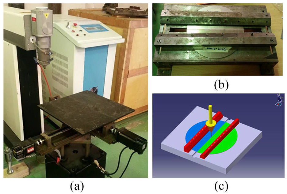
(a) Nd: YAG laser welding setup, (b) fixture to clamp the blanks, and (c) schematic of LBW process.
The constant welding parameters of LBW.
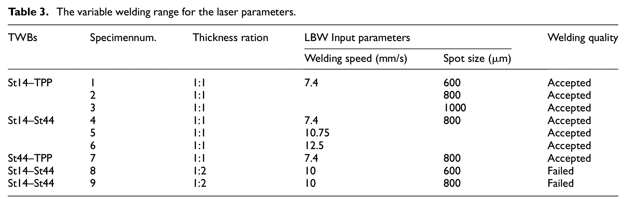
In contrast to constant parameters, to examine the effect of two parameters of welding speed and spot size on the welding quality and formability, a range of variations was considered for these two parameters. The variable welding input parameters and materials are summarized in Table 3. The Nd: YAG Laser welded specimens are presented in Figure 3. It is worth noting that samples with poor weld quality, as well as poor weld bonding and penetration, were excluded from the study to ensure the statistical adequacy of the results.
The variable welding range for the laser parameters.

Nd: YAG Laser welded specimens.
Gas Tungsten Arc Welding (GTAW) process
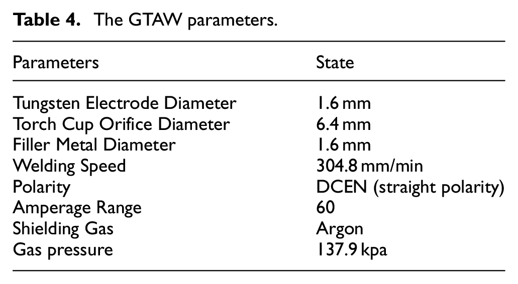
Two groups of dissimilar with identical thickness and similar with different thickness samples were welded by GTAW to evaluate the effect of material and thickness on the weld line movement and formability during the deep drawing process. The GTAW parameters were identified for all of the samples and are shown in Table 4. A high-frequency welding power supply type PSQ 250 AC/DC (Figure 4) manually welded the specimens in the GTAW process. The inert gas of 99.999% Argon was used as the shielding gas. During the welding process, the thin sheets were clamped with a C-clamp as shown in Figure 5(a). Although the weld line is narrow in the LBW and the distortion of samples is negligible, in the GTAW higher volume of the weld produces higher thermal stresses which cause the distortion of the components. It is very important to prevent the distortion of the sample during the GTAW by considering a gap between two half of samples during the welding process. In the case of similar joints with different thickness, the gap was set to be 1 mm on one side and 2mm on the other side (Figure 5(b)). In the case of dissimilar joints of 1 mm thick St14 and St44 steel sheets, the amount of gap on one side of the sheet is 0.5 mm and on the other side is 1.5 mm (Figure 5(c)). With this technique, weldments have shown no distortion after GTAW. Deformation or distortion can take place throughout welding because of the non-uniform expansion and contraction of the weld and base metal during the heating and cooling cycle. Furthermore, stresses form in the weld because of the changes in volume, particularly if the fixed components or other materials surrounding it restrain the weld. In addition, if the restraints are partly removed, these stresses can cause the base material to distort and may even result in tears or fractures. To prevent or minimize weld distortion, methods must be used both in design and during welding to overcome the effects of the heating and cooling cycle. Shrinkage cannot be prevented, but it can be controlled. To this end, several ways can be used to minimize distortion caused by shrinkage. One of the most important methods to prevent the distortion is to estimate the gap between two materials. In this study, the gap estimation was carried out by using the information and table 12.17 of AWS welding handbook. 40 Weld root openings are often 50% to 100% of the material thickness. Controlling the size of root openings is an efficient method to improve weld penetration and consistency and thus increase weld quality. 40 One of the most critical points in GTAW is the distortion caused by heat input. By using different gap size the variation of blank dimensions during the welding which caused by the heat input was controlled and the TWB remained the circle rather than ellipsoid. As Figure 5(c) shows the gap was minimum at the start point of welding and it increased until the endpoint.
The GTAW parameters.
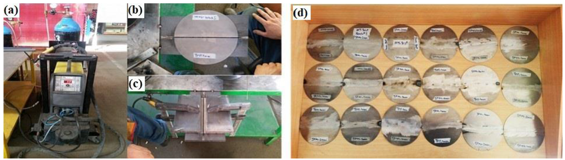
(a) GTAW process settings, (b, c) clamp setup and (d) welded specimens after the GTAW.
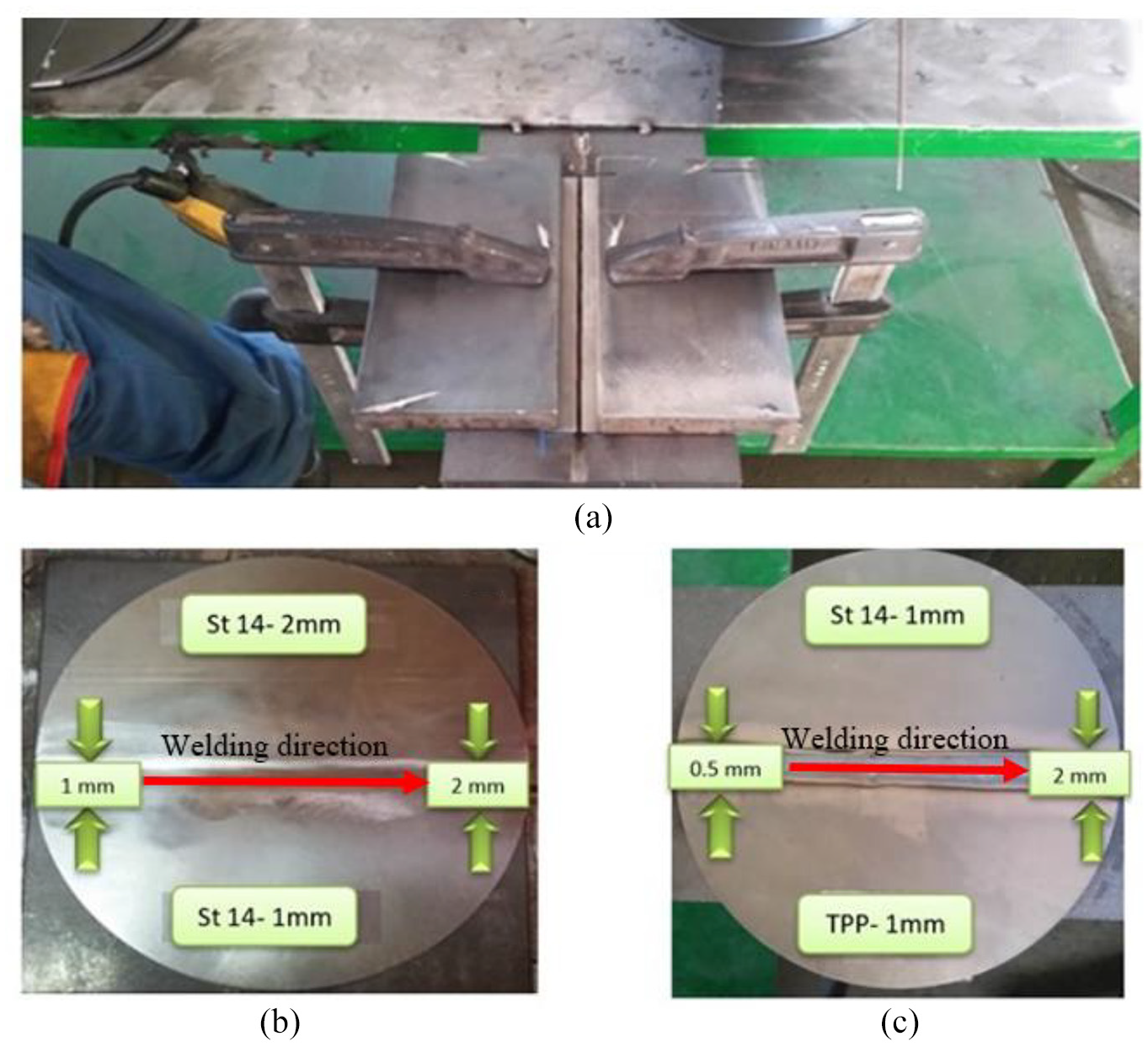
(a) C-clamp for fixing the sheets, (b) gap preset in the case of similar welding with different thicknesses, (c) gap preset in the GTAW of TWBs with different base metals.
As shown in Figure 6, the welding surfaces are polished using a polishing stone. Performing such operations will cause the elimination of some surface cracks in the workpiece as well as increase the fracture strength in the weld area. Before the formability evaluation of the TWBs in the deep drawing process, the weld surface should be grinded using a grinder stone. Performing such an operation will eliminate some surface defects and cracks from the weld region and therefore increases the fracture strength during the deep drawing test. Then the grinded specimens randomly selected for non-destructive testing through magnetic particle test (MT). No defects larger than the standard limits were detected in the weld region of the samples. Figure 7 shows the MT test of welded samples. The deep drawing test is applied to the TWBs after the visual and MT tests of the weld region.
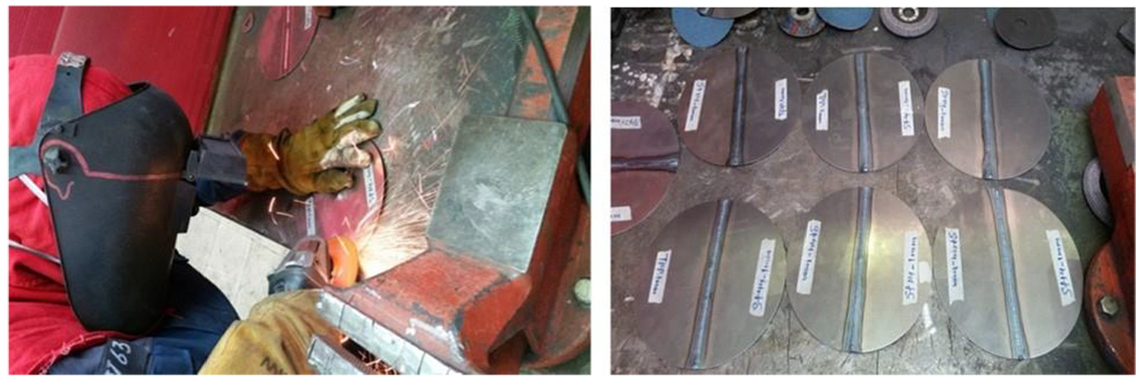
Sanding operations of sheet surfaces after GTAW welding.
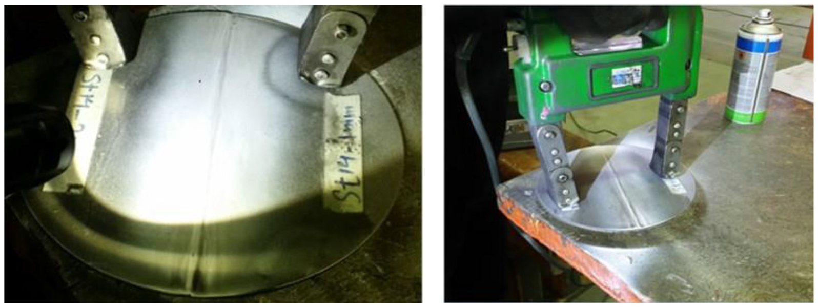
Sample preparation for non-destructive magnetic testing (MT).
Deep drawing process
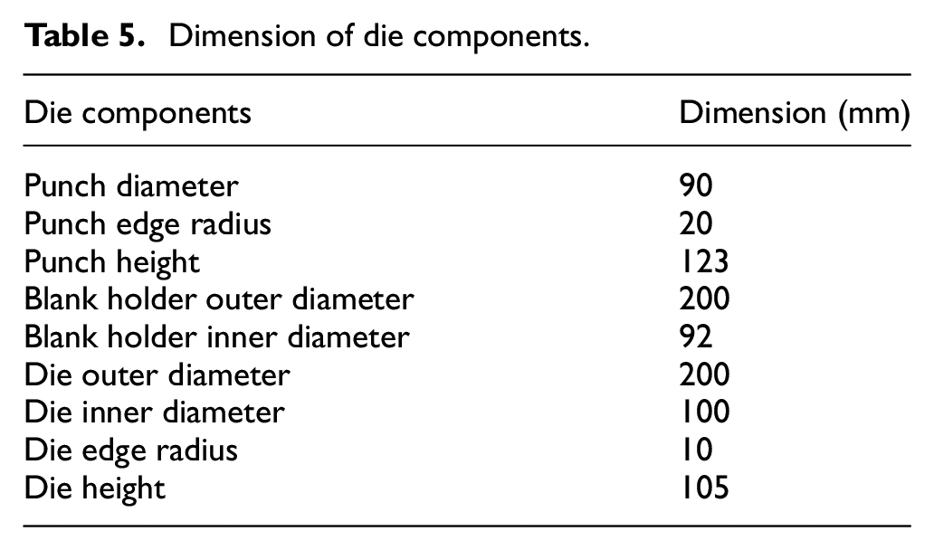
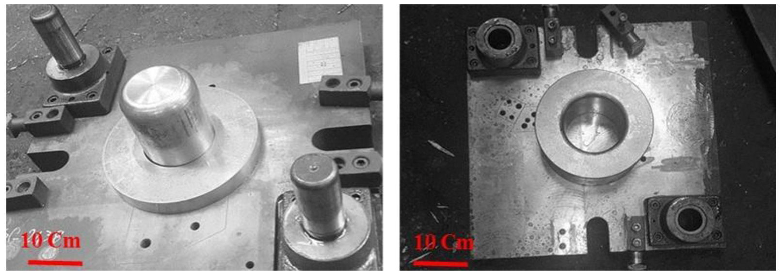
The deep drawing of laser-welded samples made of low carbon steel was performed using a 315 ton hydraulic Müller press. The deep drawing die was design and manufactured based on the information of Table 5 and presented in Figures 8 and 9. The punch and die matrix material were selected from VCN200 steel to avoid heat treatment, as well as good abrasion resistance against drawing tests. The ram speed and blank holder force (BHF) were adjusted at continues levels using the control valve of the hydraulic machine. For TWBs with different thickness a shim was used under the blank with smaller thickness. The shim thickness was equal to the difference between the base metals thickness. The micro Vickers hardness test was also used to measure the hardness profile transverse to the weld line in TWBs with a load of 50g. The hardness test was done in 10 different points according to the ISO6508 standard. As Figure 8(c) shows half circular steel sheet (shim) with same material properties and 1 mm thickness was installed between the blank holder and the thinner part of the TWB with different thicknesses. Therefore, the thickness of both sides of the TWB were equal and blankholder touched the uniform surface of the blanck. The punch surface touched the uniform surface of the TWB and there was no need to use shim between the punch and TWB surface. The friction coefficient and lubricant condition between the BHF, blank and shim were consider.
Dimension of die components.
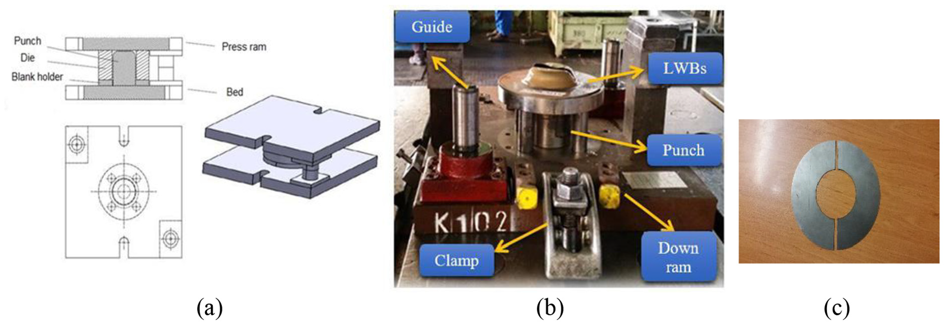
(a) CAD design of deep drawing die, (b) experimental set up of deep drawing and (c) shim in different thickness condition.
Die configuration for deep drawing process.
Results and discussion
Effect of Laser welding parameters on the formability of TWBs
The load curve of deep drawing test was used as a criterion to stop the test. The deep drawing tests were stopped when the forming load decrease suddenly. Then, the forming depth was measured by the caliper. The forming depth (deep drawing depth) increased by increasing of weld strength. Moreover, the fracture happened far from the weld line and in the weaker base metal for TWBs with acceptable weld quality.
The formability results and weld line movement of St14-TPP TWBs produced by LBW with a fixed welding speed of 7.4 mm/s and different spot sizes of 600µm, 800µm, and 1000µm are presented in Table 6. The blank holder force of 5 ton was used for all the samples. The oil-FOX with characteristics presented in Table 7 was used as a lubricant between the TWBs and punch. Samples 1 and 3 with the smallest and the largest spot size, fully separated during the deep drawing test, but the sample 2 with the spot size of 800 µm, remained virtually sound during this test. The better response of the joint with higher spot size can be attributed to the cooling rate. By the spot size increasing and hence the weld volume fraction, the cooling rate decreases which can reduce the hardness of the weld region. However, an excessive increase in this parameter enhances the possibility of immediate fracture because of the lack of fusion and lack of sound joint. In other words, by increasing the spot size in constant laser power, the power intensity (power/spot area) decreases. If the value of the power density decreases to the lower limit of keyhole formation (106W/cm2), low-quality welds are obtained. In a large spot size, the melt pool is low and by reducing the spot size, the molten pool is deeper and the depth of penetration increases. 41
The effect of spot size of LBW on the deep drawing of TWBs.
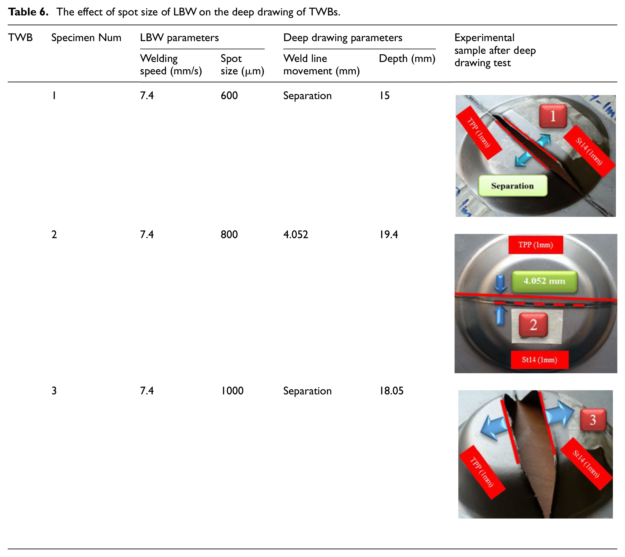
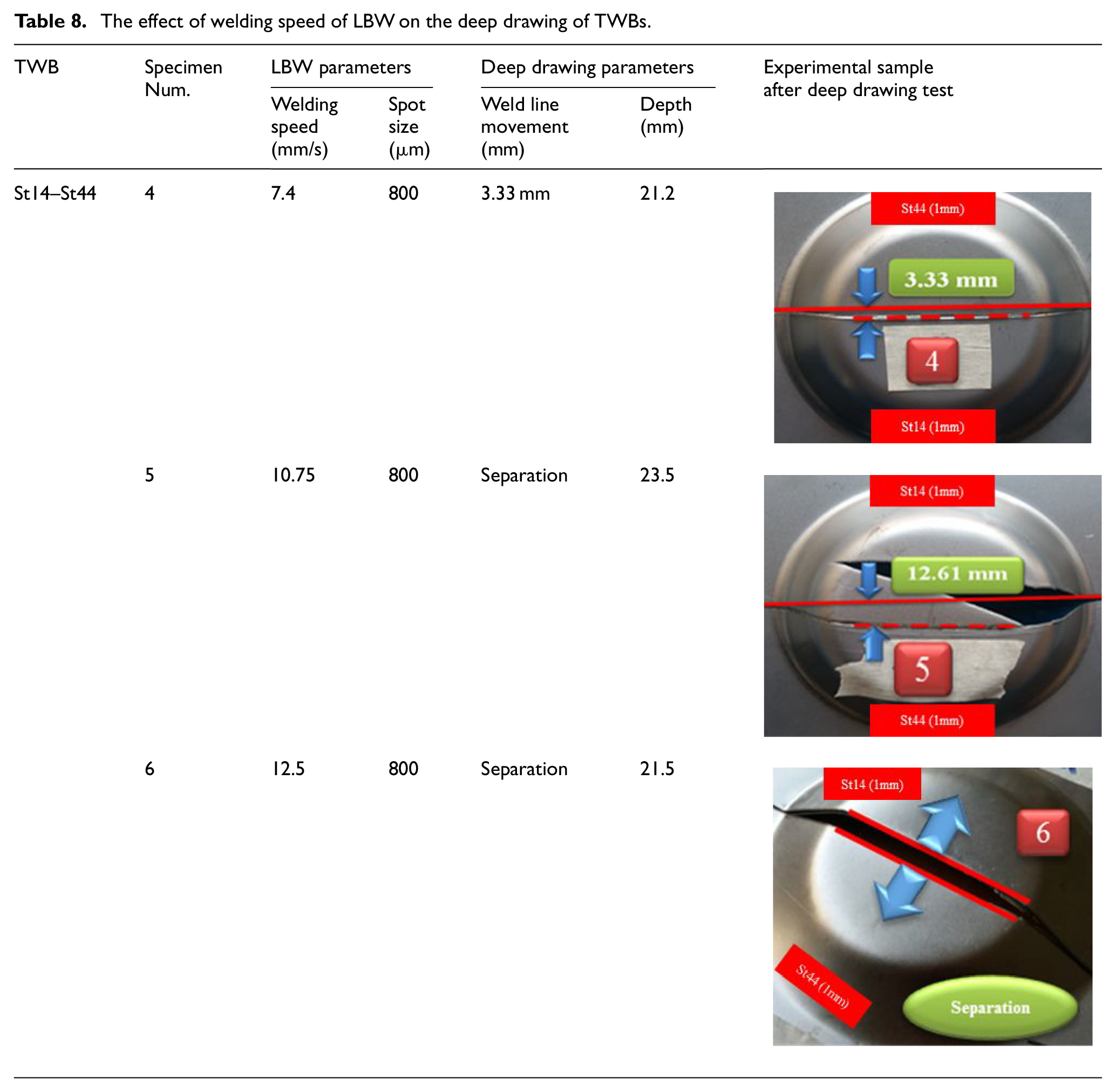
Oil technical characteristics.
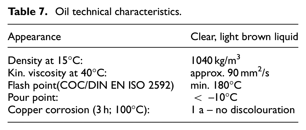
The effect of welding speed of the LBW process was investigated on the formability of St14-St44 TWB by considering three speeds of 7.4 mm/s, 10.75 mm/s, and 12.5mm/s and fixed spot size of 800 µm. Table 8 shows the parameters and results of these three tests. The blank holder force of 10 ton was used for all the samples. The oil-FOX was used as lubricant between the TWBs and die. Samples 4 to 6 are identical in all of the welding conditions excluding welding speed. With increasing the welding speed from 7.4 mm/s to 10.75mm/s, the weld line movement and the forming depth increased in sample 5. Two reasons can be suggested for such behavior. At first, increasing the welding speed decreases the porosities in the weld region and improves the weld quality, but this increase should not be as much as a value that causes lack of fusion. This result was mentioned by Han et al. 42 As a result, sample 5 is the best dissimilar laser welded blank only when a predefined strategy is adapted for weld line movement control.
The effect of welding speed of LBW on the deep drawing of TWBs.
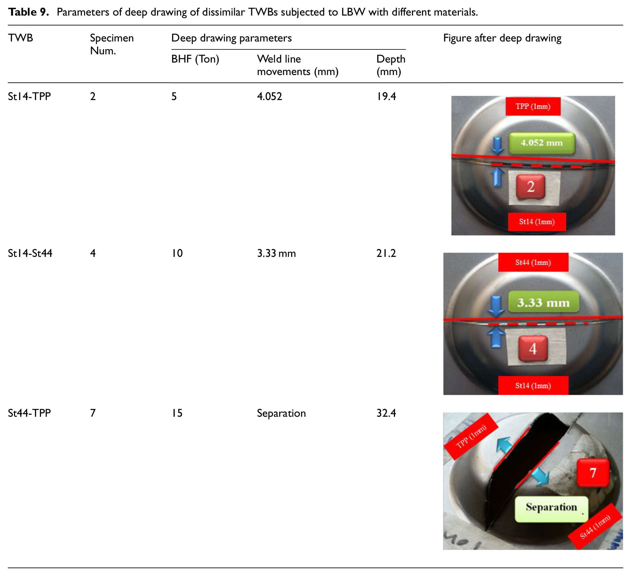
The effect of strength ratio or difference of base metals was investigated on the formability of TWBs produced by LBW by using three different base metals of St14, St44, and TPP. Three TWBs of St14-TPP, St14-St44, and St44-TPP were produced by welding speed of 7.4 mm/s and the spot size of 800 µm. The oil-FOX was used as lubricant between the TWBs and die. Different BHF was used for different TWBs. Table 9 shows the weld line movement and the forming depth of these samples. Incorrect selection of welding parameters caused the fracture of sample 7 from the weld line. Based on the information of Figure 1 the difference between the UTS of base metals of St44-TPP TWB is lesser than two TWBs of St14-TPP and St14-St44 which causes the formability increase of St44-TPP TWB. Therefore, the forming depth of St44-TPP TWB is higher than two other TWBs in Table 9 and this sample fractured from the weld line which shows that welding parameters were not selected correctly for this TWB. This result was mentioned by Safdarian 27 who study the effect of strength ratio on the formability and FLD of TWBs. The results of present study showed that the best values for welding speed and spot size in the LBW to poduce sample without fracture and with maximum forming depth was 7.4 mm/s and 800 µm, respectively. The other welding parameters of LBW were selected based on the information of Table 2.
Parameters of deep drawing of dissimilar TWBs subjected to LBW with different materials.
Effect of GTAW parameters on the formability of TWBs
The results of the gas tungsten arc welded blanks subjected to deep drawing, parameters of the deep drawing, weld line movement and the maximum depth in cups based on the effect of BHN and lubricant are represented in Tables 10 and 11.
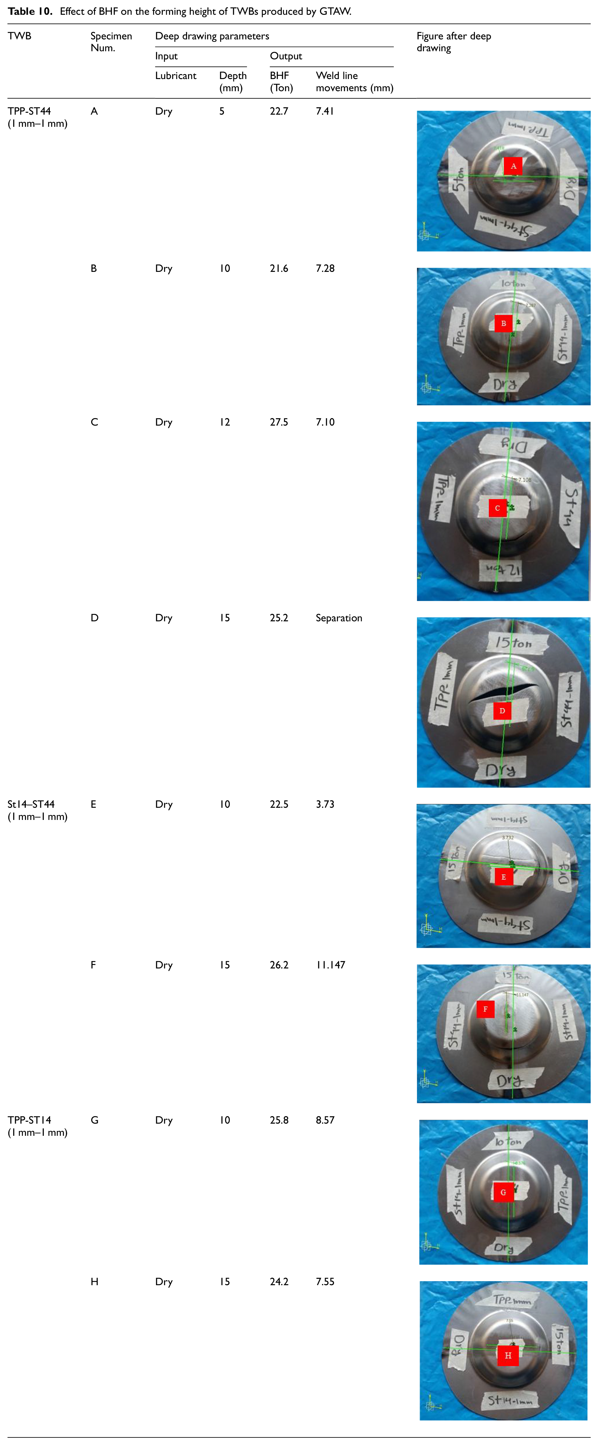
Effect of BHF on the forming height of TWBs produced by GTAW.
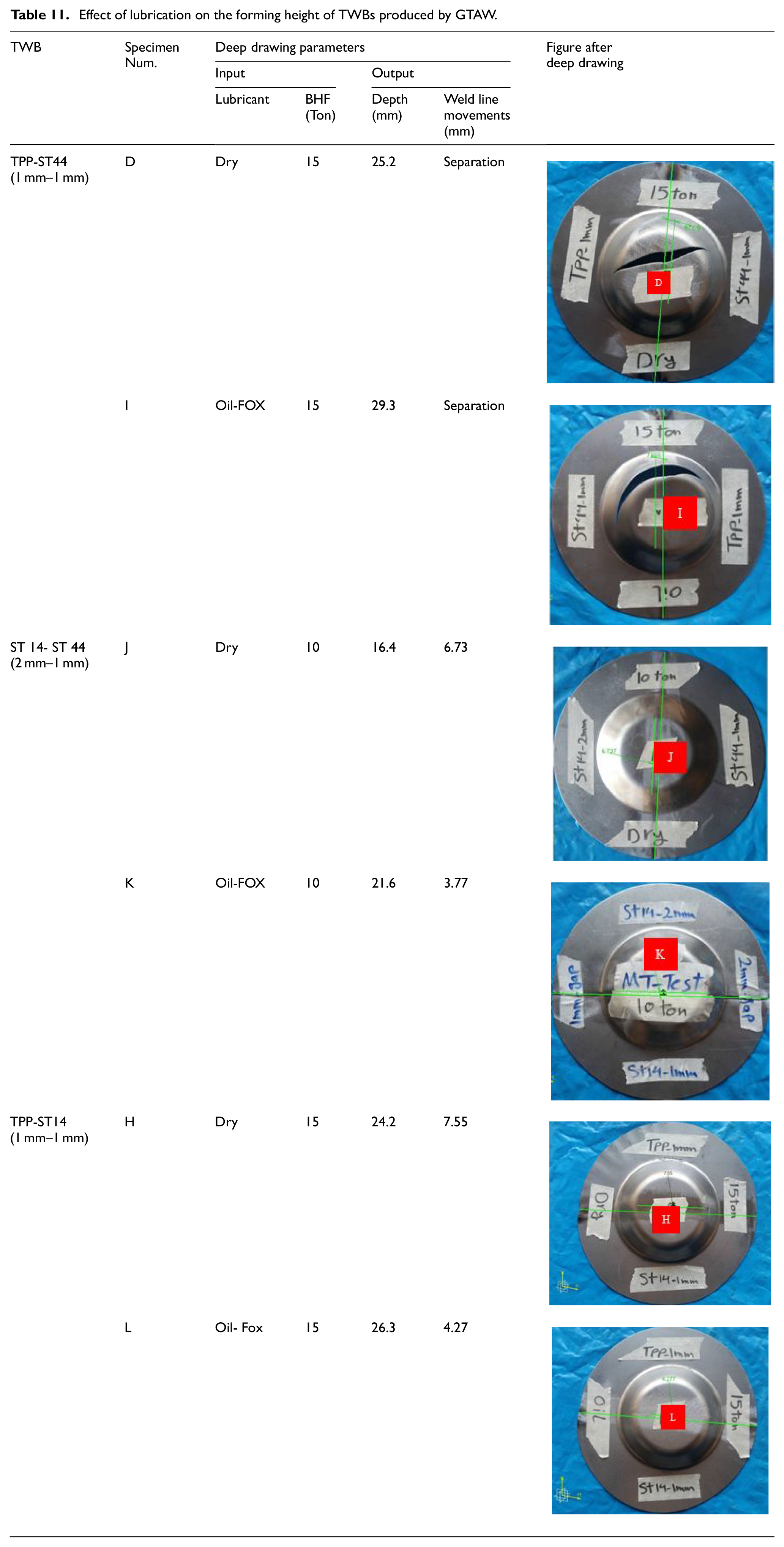
Effect of lubrication on the forming height of TWBs produced by GTAW.
The effect of blank holder force (BHF) was investigated on the formability and forming depth of TWBs produced by GTAW. Table 10 shows the effect of BHF on the forming depth and weld line movement of TWBs in the deep drawing process. The dry condition was used between the punch and TWB for all of the samples. The increase of BHF from 5 ton to 12 ton caused the increase of forming depth from 22.7 mm to 27.5 mm for TPP-St14 TWB, but the increase of BHF to 15 ton caused the fracture of the sample and decrease of forming depth to 25.2 mm. The weld line movement decreased by the BHF increase for TPP-St14 TWB.
The effect of lubrication on the formability of GTAW is shown in Table 11. As this table shows for all of TWBs the forming depth increased and the weld line movement decreased by using lubricant in the punch and TWBs contact.
Hardness comparison
Figure 10 shows the hardness profile transverse to the weld line for St14-St44 TWBs welded by two different welding processes of LBW and GTAW. As it is obvious, no sharp increase in the hardness in the fusion zone was detected. Therefore, it can be concluded that no martensite phase was formed in this region and the weld can sustain enough formability without failure. That is why failure shifted to the weaker base material (St14) in sample 5. Martensite formation would increase the hardness to nearly 700 HV or more in steels and cause brittleness of the weld. It was reported that the hardness of the weld region in laser-welded blanks is much higher than the base materials which can reduce the formability of the TWBs and controls the failure of the final part. Tušek et al. 43 introduced a hardness criterion for successful TWBs. They claimed that the formability of the weld region should be equal or less than the base materials. They found that the hardness in the welding region should be below 200 HV.
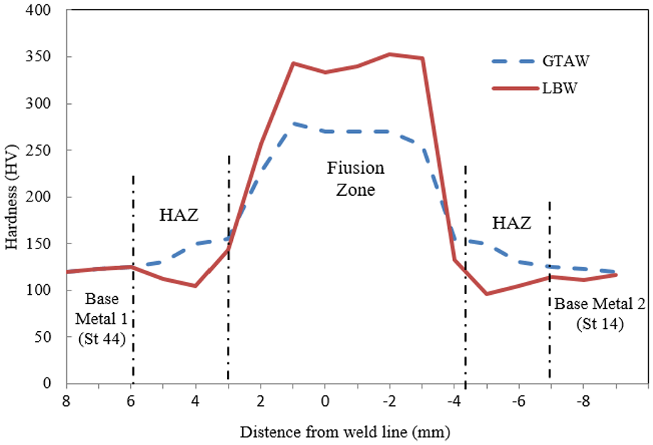
Hardness profile transverse to the dissimilar St14-St44 TWBs for welded samples by LBW and GTAW.
The results of microhardness measurement analysis show that the microhardness values of laser welded in the molten area are higher than the GTAW samples because of higher energy concentration, welding speed, and higher cooling rate in laser welding. Laser welding has a higher melting zone temperature than the GTAW, which causes the cooling rate to be higher in the molten zone, and as the cooling rate increases, it prevents recrystallization and further grain growth and forms brittle phases. This increases the microhardness and decreases the formability of laser welding compared to GTAW. In metals, hardness and formability are generally inversely correlated and, as hardness increases, formability decreases. The results of deep drawing also show that the criterion of formability (forming depth) in GTAW welding is higher than laser welding.
The first major difference between the GTAW and LBW methods is that the laser welding process has a much higher energy density than GTAW. However, laser welding has slightly region of Heat Affected Zone (HAZ). Figure 11 shows an overview of the weld region of LBW and GTAW. Based on figure 11, the weld line in the laser welded sample is flat and thin. High velocity with high energy input of laser welding causes the metal to melt in a shorter time, and the rate of cooling and freezing in this method is higher than that of the GTAW. In addition, the HAZ region in laser welding is much smaller than GTAW, because the freezing rate in the laser welding will be much faster and the seeds do not have enough time to integrate and shrink.
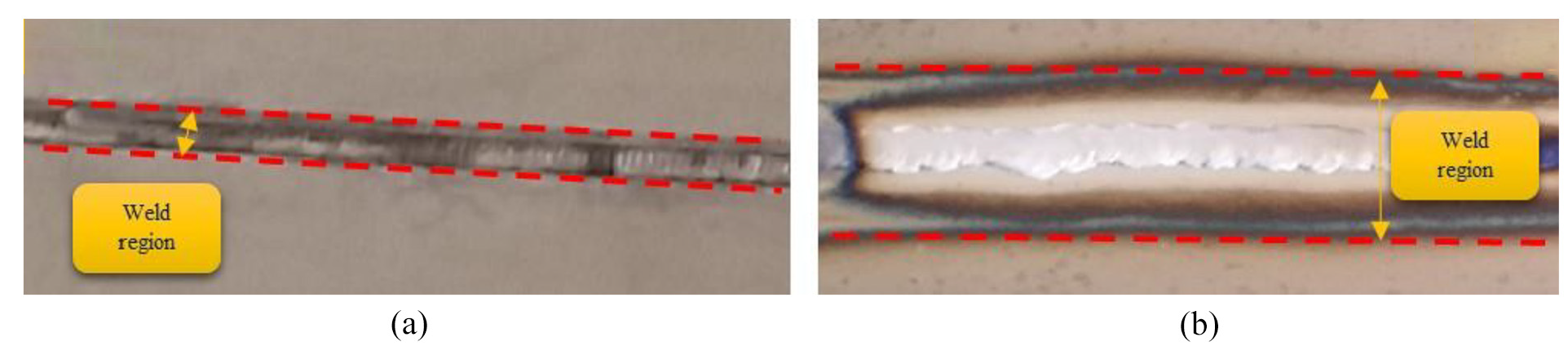
Comparison of weld region of (a) LBW and (b) GTAW.
Conclusion
Based on experimental analysis of tailor welded blanks with different materials and thicknesses during the LBW and GTAW, the following conclusions can be drawn:
Welding of dissimilar TWBs is possible under certain conditions. In the case of LBW, the optimum welding parameters for dissimilar welding of 1 mm St14 to 1 mm St44 is 800 µm laser spot size with 10.7 mm/sec welding speed. In the case of GTAW, the welding current of 60A produced an acceptable weld quality for TWBs with dissimilar blanks.
Decreasing the welding speed and spot size in LBW, decreases the mechanical properties of the TWBs and the weld metal controls the failure during the deep drawing test.
During the deep drawing test of the optimum LBW sample, the steel with lower strength (St14), controlled the failure of the blank.
TWB with thickness ration of 2 (St14 1 mm/St14 2 mm) was failed to be welded by LBW, but the GTAW could produce better TWB in this case.
Footnotes
Declaration of conflicting interests
The author(s) declared no potential conflicts of interest with respect to the research, authorship, and/or publication of this article.
Funding
The author(s) received no financial support for the research, authorship, and/or publication of this article.