
Abstract
In this study, a new process namely, ultrasonic-assisted jet electrodeposition, has been conceived. The ultrasonic-assisted jet electrodeposition process integrates the use of ultrasonic vibrations and high-speed selective jet electrodeposition process to fabricate micro shapes with comparatively high accuracy and with no edge effect. The present study focuses on the development of ultrasonic-assisted jet electrodeposition setup. The impacts of voltage, pulse on time of ultrasonic vibration, concentration of CuSO4·5H2O and interelectrode gap for the fabrication of square-shaped micro part have been studied. Deposition rate and dimensional accuracy of fabricated micro features were considered as responses. The experimental results showed that the ultrasonic-assisted jet electrodeposition process has the capability to fabricate micro parts, which yield better dimensional accuracy and no edge effect but waviness of the order of 10–50 µm, as compared to uneven depositional width and edge effect (gap of 200–250 µm) obtained by jet electrodeposition process.
Keywords
Introduction
In electrodeposition process, the deposition of metal onto a surface is achieved. This is performed by dipping anode and cathode (i.e. surface to be deposited) in electrolyte solution. Normally, anode is made of the same metal as that of metallic ions in electrolyte solution, which are going to be deposited at cathode surface. A potential difference is applied between two metallic electrodes, that is, anode and cathode. Anode gets dissolved in this process in the electrolyte solution as ions. These ions are carried by electrolyte to the cathode surface. Negative potential is applied to the cathode with respect to anode, and the metal ions are deposited by reduction at cathode.
Jacobi was the first person to register electrodeposition process in 1837 as a significant process that has the capability of producing large features. 1 Electrodeposition process when utilized for manufacturing parts or components is recognized as electroforming. 1 Electrodeposition process is one of the basic manufacturing processes that have capability to manufacture three-dimensional shapes/parts having very good accuracy and material properties. 1 In the last century, electrodeposition process has regularly progressed into a micro feature fabrication technique. The recent technological developments in the direction of rapid manufacturing of micro features are namely, high-speed selective jet electrodeposition (HSSJE) 2 and ultrasonic acoustic liquid manipulation–assisted electrodeposition (UALMAE). 3 Both the processes are relatively new concepts and are at the stage of infancy. These two processes can also be used for the fabrication of micro electro mechanical systems (MEMS).
Acoustic assisted jet plating was studied by Gutfeld et al. 4 Their plating process is combination of HSSJE and UALMAE process. HSSJE process has been used to fabricate micro-molds, microelectrodes for electric discharge machining (EDM) process and micro-features.2,5 The process can also be used for the fabrication of MEMS. Acoustic liquid manipulation (ALM)-assisted electroplating was used by Gadkari and Nayfeh 3 to fabricate micro parts. The important literature in the related field has been denoted in the following.
Dover et al. 2 studied the possibility of using HSSJE for rapid manufacturing of micro metallic structures. They investigated the built mechanism of HSSJE process, that is, layer-by-layer deposition. They fabricated micro-sized injection mold cavities and EDM electrodes using HSSJE process. Inaccuracies like edge effect and geometrical inaccuracies appeared on fabricated features in vertical as well as horizontal directions. They observed that small pins and shallow sloping side kind of geometric shapes were more difficult to fabricate.
Gadkari and Nayfeh 3 observed that the ALM-assisted electroplating has reduced need for masking and could be used for rapid prototyping of micro parts. They found that the size of surface transferring the vibration to electrolyte, the dimensional size of the point at which waves are meeting (focus) and the location of the deposition point with respect to the focus determined the magnitude of deposition dot size. Optimum streaming power was applied to produce laminar acoustic beam. This resulted in increased accuracy of deposition dot. Low metal ion concentration with high current values resulted in best depositions. Higher height of deposited structure was obtained at increased processing time.
Gutfeld et al. 4 performed jet plating with a focused acoustic beam converging at center of the jet. Plated structures of copper and gold were having better morphology due to decrease in diffusion layer thickness and increase in current density. They did not find any improvement on deposition rates over conventional jet plating.
Kunieda et al. 5 observed that the maximum amount of electric current flows through the impingement zone as compared to the other regions in HSSJE process. They inserted the lapping process between each deposition cycles and kept low temperatures (˜15 °C) of the electrolyte to maintain dimensional accuracy of the parts. In their experiments, they utilized copper nitrate and copper sulfate–based aqueous electrolyte solutions. Using copper nitrate aqueous solution, they successfully fabricated a copper micro part.
Fletcher and Oliver 6 developed HSSJE. In this process, no masking and no tank dipping were required. Their system involved a nozzle assembly with a small jet opening, which was supplied with electrolyte solution under high pressure. The nozzle was given motion relative to depositing surface (cathode) at a selected rate and in a particular pattern with the electrolyte solution impinging on the cathode. A potential difference was then maintained between depositing surface (cathode) and electrolyte solution to selectively electrodeposit the surface. Their process was used to only plate the surface.
Oeftering and Denofrio 7 patented two methods for selective deposition in which directed beams of high-intensity acoustic waves were focused on the work surface to create beam of fresh ions in electrolyte solution that caused higher rate of deposition at selected region. In the first method, one element was immersed in electrolyte solution. Then the element of ultrasonic transducer transmitted ultrasonic vibration to electrolyte solution. These vibrations caused a beam of fresh electrolyte by the streaming effect of acoustic waves toward the work surface and resulted in selective deposition. In the second method, an array of ultrasonic transducer elements was suspended in the electrolyte. The elements were faced toward the work surface. The high-intensity acoustic beams were formed by selectively turning on and off the transducers. These beams can be used for selective deposition on the work surface. They reported that both the processes developed in certain parametric conditions were capable of performing selective plating over the work surface with precise control of thickness of the plating.
Literature review presented above reveals that very few attempts2,5 have been made to perform HSSJE for fabrication of micro parts. Researchers2,5 have studied the effects of current and lapping interval between scans of jet on the build height and accuracy of feature. Very few attempts3,7 appear to be made to perform the selective electroplating using ultrasonic ALM. One attempt 3 appears to be made to apply ALM-assisted electrodeposition to fabricate micro parts. Despite the immense capabilities of HSSJE and ALM-assisted electrodeposition in the field of micro fabrication, these processes are not much explored. Fabricated features created by HSSJE process contain horizontal inaccuracies. These inaccuracies may be reduced by proper selection of nozzle diameter and current control. Similarly, in ALM-assisted electrodeposition, minimum diameter of produced feature was 0.78 mm. This may further be reduced by the proper focusing of ultrasonic waves at one point. This single point can be used to fabricate micro parts by giving the movement to the deposition point.
The objective of present investigation intends to combine the principles of ALM and speed jet electrodeposition to improve the accuracy of the fabricated features. This article presents performance evaluation of the ultrasonic-assisted jet electrodeposition (UAJE) process by conducting experiments with important process parameters such as voltage (V), concentration of metallic ions (Cn), that is, CuSO4·5H2O, pulse on time (Ton) of ultrasonic vibrations and interelectrode gap (Ga). Experimental study using HSSJE process has also been performed to prove efficacy of UAJE process over existing selective jet electrodeposition process. Scanning electron microscopy (SEM) and micro hardness tests are carried out to characterize the fabricated feature. The dimensions of fabricated feature have been measured using Dino Lite Digital Microscope.
UAJE setup design and experimentation
In this section, details of nozzle assembly, the experimental setup, selection of process parameters and the experimental procedure have been discussed.
Details of nozzle assembly
In the present study, nozzle assembly with ultrasonic transducer is designed and fabricated with other components of experimental setup, as shown in Figure 1. The nozzle assembly involves stainless steel adaptor in which at one end nozzle (137 µm opening diameter) is connected; on the other side, horn of the ultrasonic generator is inserted and a side opening is given to supply the pressurized electrolyte to the assembly, as shown in Figure 2. The advantage of this design is to combine both jet electrodeposition and ultrasonic energy so that the overall performance of the process can be improved. This combination provides the ultrasonic energy to the jet, which enhances the mass transfer and distribution of ions at the interface between the electrolyte and workpiece. Ultrasonic energy provides acoustic heating at deposition zone. The acoustic heating improves the plating quality.3,7 Ultrasonic acoustic beam, which is carried by the jet, strikes at the workpiece surface and gets reflected back. These beams interact with incoming beams, as shown in Figure 3(a) and (b). This interaction causes proper and enhanced distribution of the metallic ions, which are being deposited.3,7
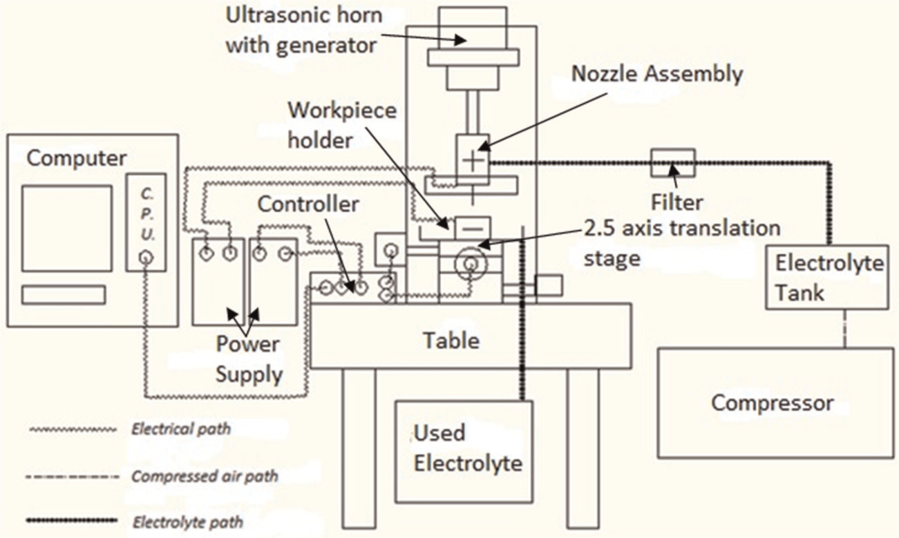
Schematic diagram of UAJE setup.
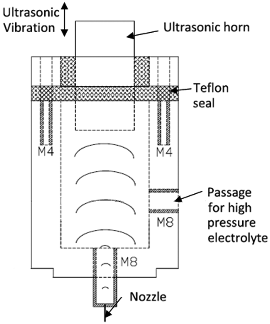
Block diagram of nozzle assembly.
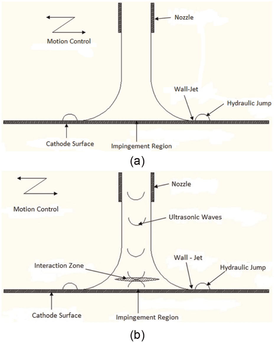
Schematic representation of (a) the high-speed selective jet electrodeposition process and (b) acoustic streaming within the electrolyte jet.
Details of experimental setup
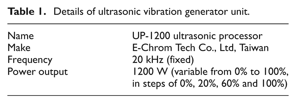
The designed experimental setup for fabrication of metal micro part using UAJE consists of a nozzle assembly with an ultrasonic generator, electrolyte tank, direct current (DC) power source, compressor and 2.5-axis motion controller with accessories. The nozzle is connected to a DC power source (0–30 V) to make it anode and workpiece is connected to the negative terminal to make it cathode. In this setup, electrolyte of 1 M sulfuric acid concentration has been supplied in the nozzle at a pressure of 1.5 kg/cm2. The actual picture of entire assembly is shown in Figure 4(a) and (b). The nozzle with an ultrasonic generator is connected to a single-axis translation stage to control the position of ultrasonic horn in nozzle assembly. A tank with workpiece holder is attached to x, y (computer controlled) and manually operated z-axis translation stages. Workpiece holder is used to hold the substrate surface. Nozzle is connected to the positive terminal of the DC power source. Substrate surface is attached with the negative terminal of power source to act as cathode. The pressurized air of the compressor is supplied to the stainless steel sealed electrolyte tank, and output of the stainless steel sealed electrolyte tank is attached to the nozzle assembly to supply pressurized electrolyte. The electrolyte reaches to the nozzle assembly at approximately equal pressure to the supplied air pressure to the tank. Electrolyte is expelled out as jet from the nozzle opening. SEM image of a used nozzle opening is shown in Figure 5. Upon energizing the nozzle (anode) and workpiece (cathode), electrolyte jet starts carrying the current. To provide ultrasonic waves to the jet, an ultrasonic vibration generator unit (Table 1) is attached at the nozzle assembly, as shown in Figures 2 and 4(a). Horn of ultrasonic vibration generator unit is inserted into one side of nozzle assembly through teflon seal, as shown in Figure 2. The amplitude of vibration (at 720 W power mode; refer Table 1) is recorded using Fast Fourier Transform (FFT) analyzer and piezoelectric transducer. The piezoelectric transducer is attached to the end ultrasonic horn in assembled condition of setup and ultrasonic transducer is turned on. These vibrations are then recorded by FFT analyzer, as shown in Figure 6. This vibration is transmitted to electrolyte. In experimentation, 720 W power mode output of unit is utilized. The horn of ultrasonic transducer transmits ultrasonic vibration at 20 kHz to the electrolyte. Ultrasonic waves travel within the electrolyte and reach to workpiece through this nozzle assembly and electrolyte jet.
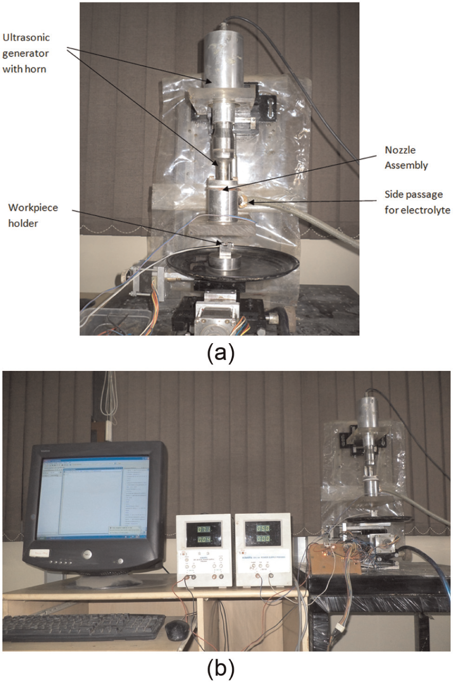
(a) Nozzle assembly of UAJE setup and (b) complete UAJE setup.
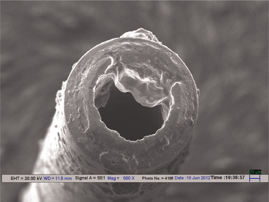
SEM image of nozzle opening.
Details of ultrasonic vibration generator unit.
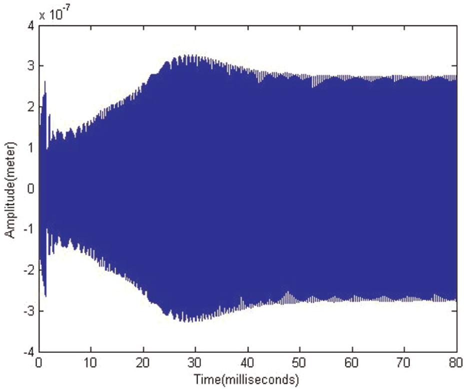
Ultrasonic vibrations (at 20 kHz) transmitted to electrolyte.
Electric current density in the jet can be varied by changing input voltage to the nozzle and workpiece, and it is measured using a multimeter (model Auto-Range DMM SM7022, make scientific). The current is found in between 1 and 25 mA. Current is difficult to control; therefore, for the study purpose, voltage is taken as a parameter instead of current. The value of current depends upon the voltage, interelectrode gap and concentration of electrolyte. The current density is enormously high in the impinging jet zone on the substrate as compared to other regions 5 due to contact through conducting medium (electrolyte) to the nozzle (anode). This accounts for the maximum deposition at impinging zone. The copper sulfate aqueous solution is used as electrolyte to deposit the metal on workpiece. The substrate (cathode) material selected in this present study is a copper plate of 0.3 mm thickness.
Experimentation
The range of controllable process parameters is selected on the basis of pilot experiments. The parameters selected for experiments are voltage (V) and concentration of metallic ions (Cn), that is, CuSO4·5H2O, pulse on time (Ton) of ultrasonic vibrations and gap (Ga). The voltage between cathode and anode is varied between 3 and 7 V for experimentation. The solution is prepared by varying 16–20 g/L concentration of CuSO4·5H2O. The H2SO4 is mixed in solution at 1 M concentration on the basis of the previous literature. 2 The pulse on time for ultrasonic transducer is varied from 0.3 to 0.7 s at an interval of 0.1 s, and it is kept constant during experiment. Pulse off time (Toff) is selected as 0.4 s and is kept constant for all the experiments. The distance between nozzle tip and deposition surface is maintained between 1 and 3 mm at the interval of 0.5 mm. UAJE process is started by turning on ultrasonic transducer and maintaining potential difference between nozzle and substrate surface. The structure is then fabricated by properly moving deposition surface relative to nozzle opening.
Based on the pilot experiments, fabrication time is decided for all the experiments. The fabrication time of processing is selected to be 60 min. The parts fabricated are studied under SEM. The edge effect is observed in features fabricated by jet electrodeposition. Gap found while attempting for continuous deposition is known as edge effect and is obtained in the range of 200–250 µm (gap). The elimination of this edge effect is observed at 0.3 s pulse on time for ultrasonic vibration. Therefore, pulse on time for experiments is kept above 0.3 s. This discontinuous deposition is not detected in the features fabricated by UAJE process. The dimensions of fabricated parts are measured using Dino Lite Digital Microscope. The feed rate for experimentation is kept constant at 2 mm/min. At low feed rate (below 1.5 mm/min), the deposition obtained was having a staircasing (shallow slopes)-like structure due to high deposition rate. Therefore, the feed rate is kept above 1.5 mm/min. Weights of substrates after and before the deposition process have been measured. The feature is fabricated by scanning the jet in square shape of 1000 µm edge length. The relative path of electrolyte jet with respect to substrate and schematic diagram of square feature, wall thickness and side length is shown in Figure 7. The path is scanned to gain the desired height of part (to get thicker depositions).
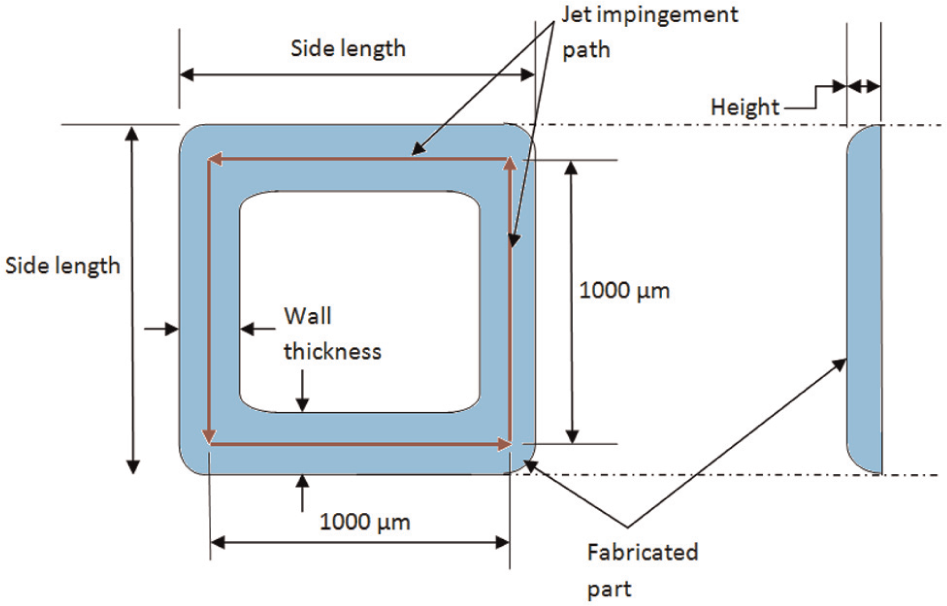
Jet impingement path and proposed fabricated part.
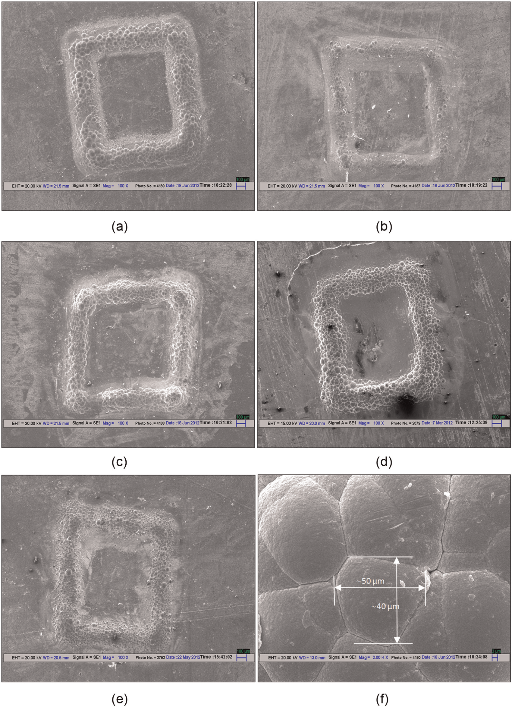
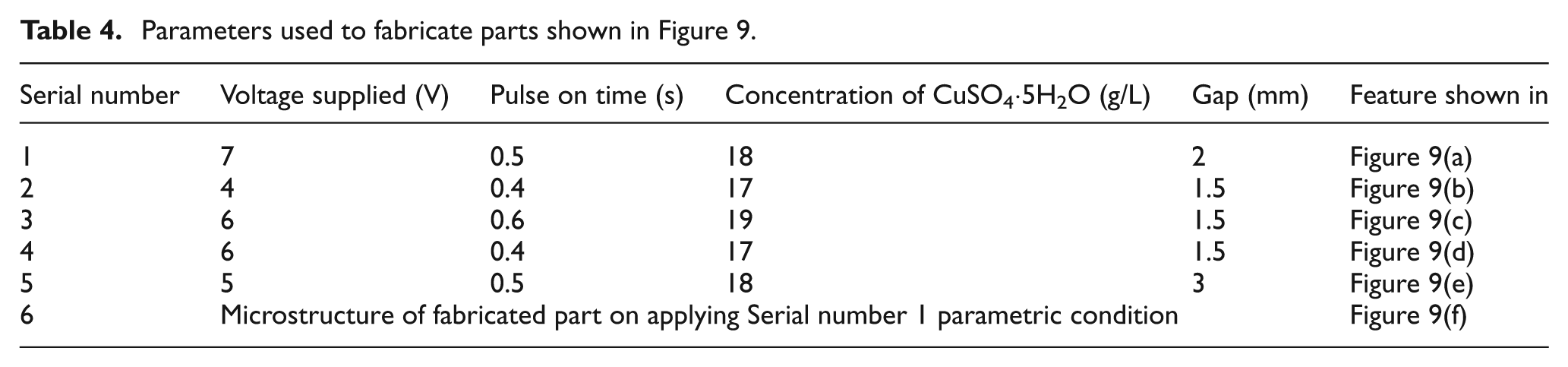
Energy-dispersive X-ray spectroscopy (EDX) analysis of workpiece material and deposited part material was conducted. Composition of workpiece material and part material is presented in Tables 2 and 3, respectively. Silicon is observed in workpiece and traceable amount sulfur is registered in the case of EDX analysis of fabricated sample. The SEM image of fabricated feature without any ultrasonic vibration is shown in Figure 8. Edge effect is observed in the feature. SEM images of fabricated parts with ultrasonic waves are shown in Figure 9. The process parameters used to produce these components, as shown in Figure 9, are summarized in Table 4. Features are fabricated successfully without inserting lapping process or any sensor-based current control. Experimental studies clearly show that the features fabricated by UAJE process had no edge effect or very less waviness. The measurement of some fabricated feature has been shown in Figure 10, and the corresponding parameters are tabulated in Table 5.
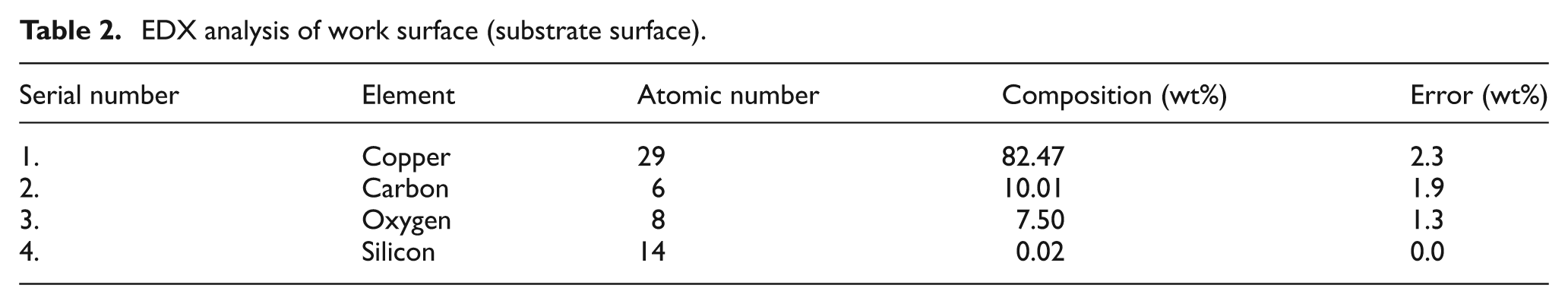
EDX analysis of work surface (substrate surface).
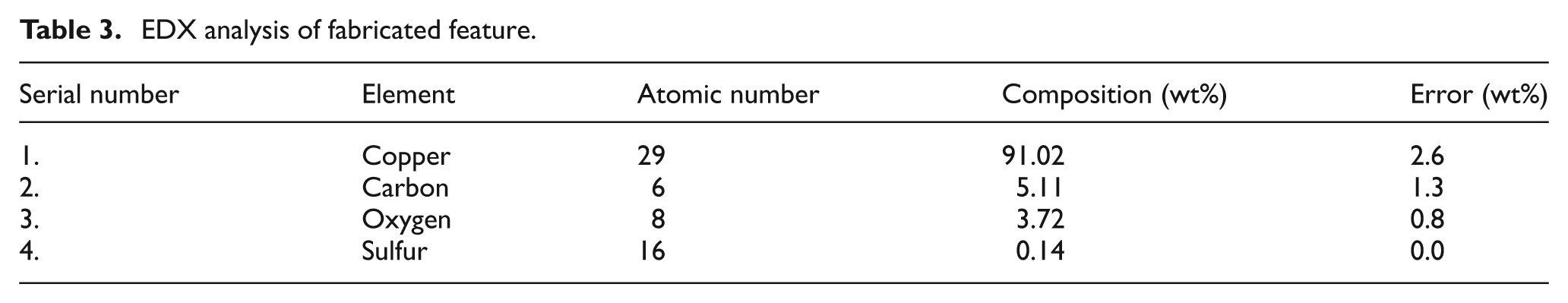
EDX analysis of fabricated feature.
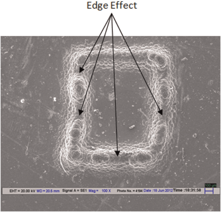
SEM image of micro features produced without any ultrasonic waves at 5 V, 18 g/L and 3 mm gap.
SEM images of fabricated features
Parameters used to fabricate parts shown in Figure 9.
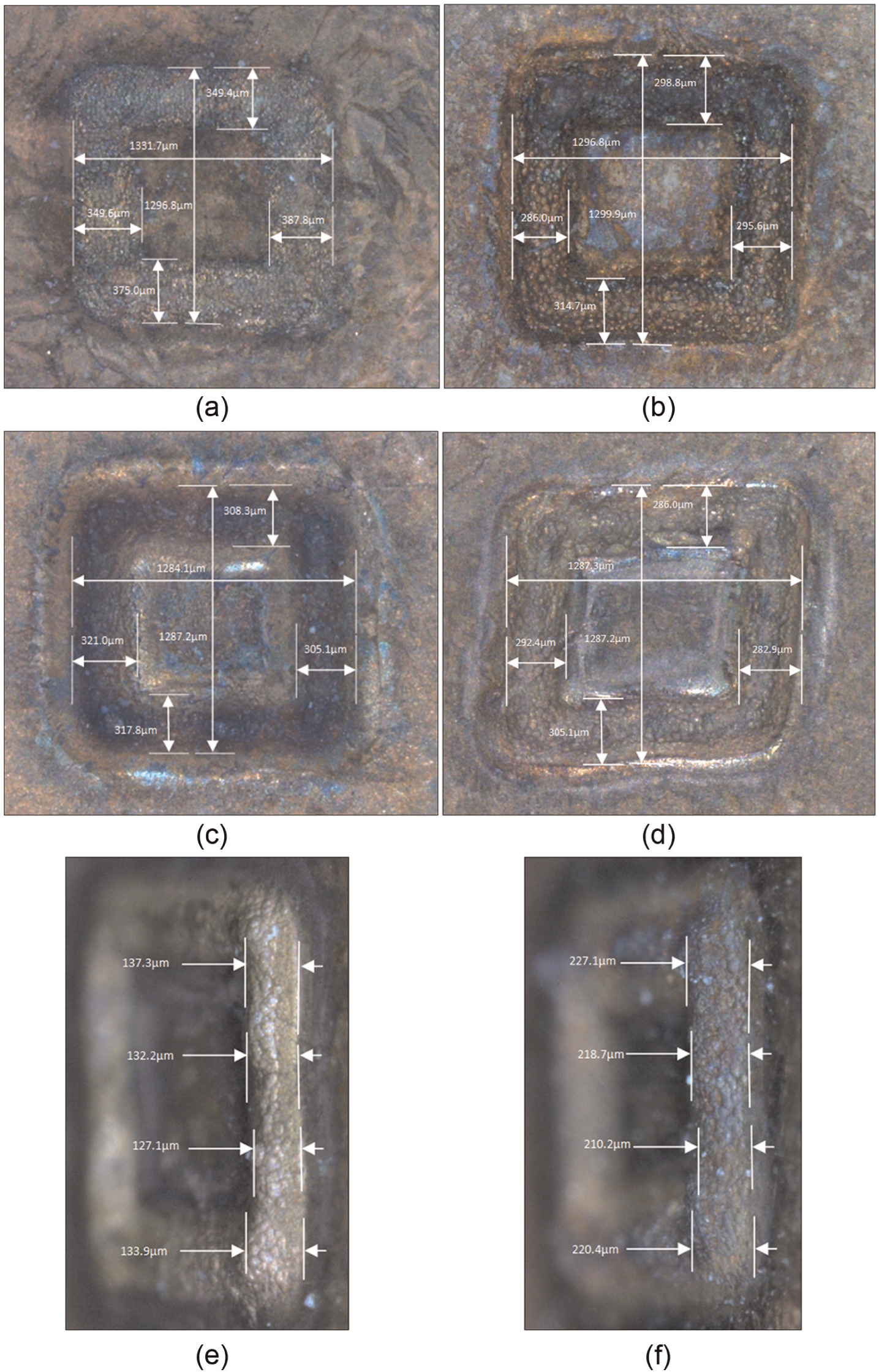
Measurement of some of the fabricated features.
Parameters used to fabricate measured feature, as shown in Figure 10.
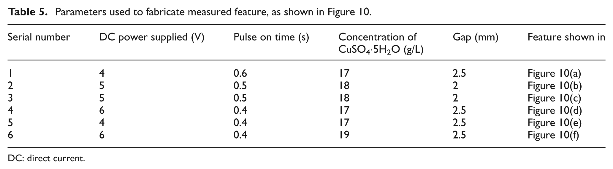
DC: direct current.
Experimental design and statistical modeling
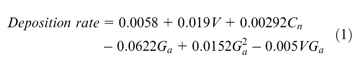
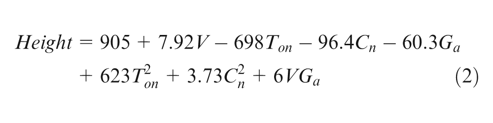
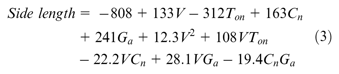
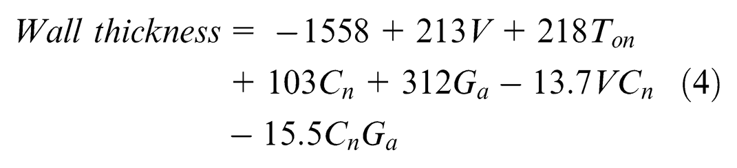
A nicely drafted experimental plan can essentially lessen the experiments. This can reduce the time and lower the cost involve in experimentation. Therefore, for studying behavior and response of parameters, the experiments are conducted as per the central composite second-order design.8,9 In the present study, four factors are selected. The factors (parameters) and their range are selected as explained in the previous section. Analysis of variance was performed to create adequate statistical models on the basis of F statistics for a 95% confidence level. The obtained models were complicated and had too many terms. Therefore, terms that have insignificant effect on responses are neglected. Following regression models are obtained to predict output variables
Due to experimental error, estimated deposition rate, height, width and wall thickness are subjected to uncertainty. The precision of the predicted model is represented by confidence interval (δ). Confidence interval is given by the following equation (5)8,9
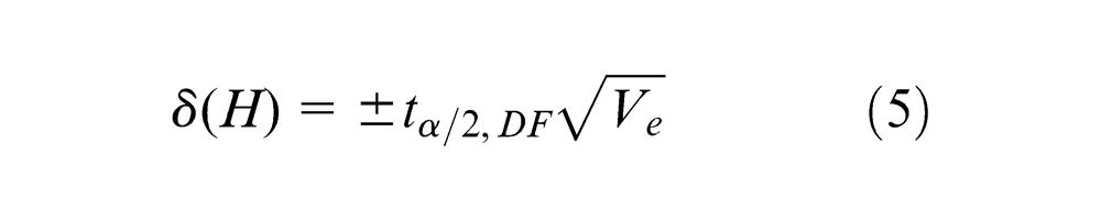
Here t is the value of horizontal coordinate on t distribution table corresponding to specified degrees of freedom (DF), at α/2 column; here α is the level of confidence interval, and Ve is the variance of error of the predicted model.8,9 The confidence intervals for deposition rate, height, side length and wall thickness of fabricated feature are ±0.0082 mg/min, ±21 µm, ±36 µm and ±21µm, respectively, for 95% confidence level.
Results and discussion
Effects of process parameters on deposition rate of fabricated features
Deposition rate has been found to be dependent on applied voltage. It also depends on the concentration of CuSO4·5H2O and gap between substrate (work) surface and nozzle. The percentage contributions of process parameters and their interactions are shown in Figure 11. Effect of these parameters has been depicted in Figure 12(a) and (b). When voltage is applied between nozzle and workpiece, it creates an electric field and because of that Cu++ and H+ ions start carrying charge from anode (nozzle) to cathode (workpiece). When Cu++ and H+ ions reach to the cathode, Cu++ ions gets reduced and it is deposited as copper 10 and H+ ion after reduction forms H2 gas. Chemical equations showing the reactions are given in the following
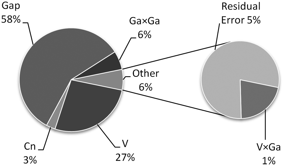
Percentage contribution of factors and interactions on deposition rate.
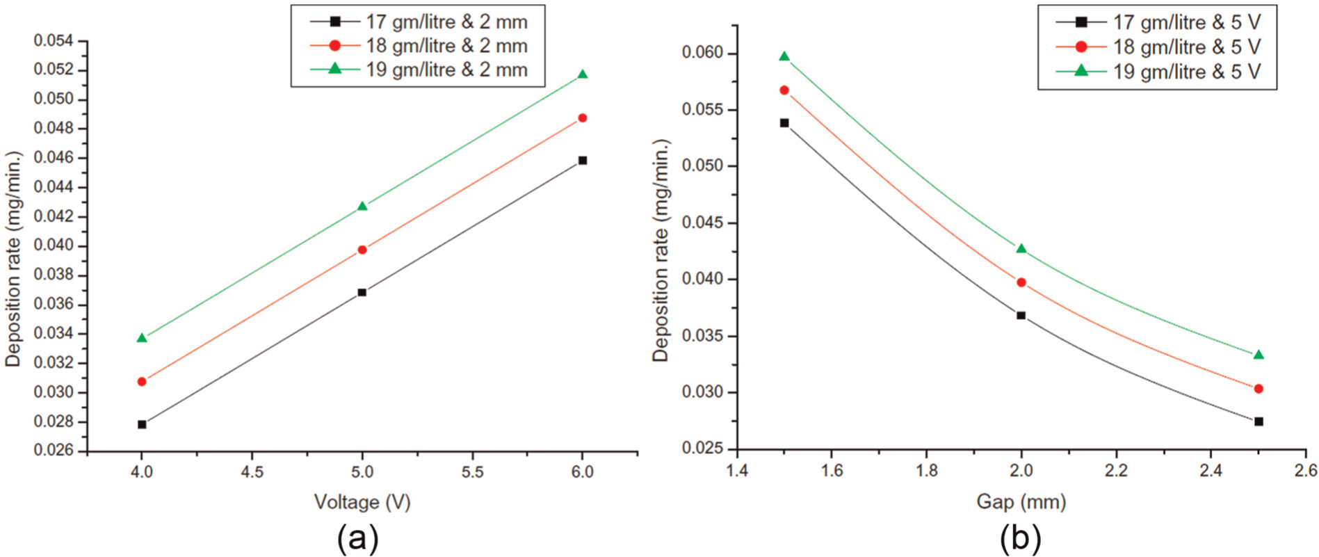
Variation of deposition rate with (a) voltage and concentration of CuSO4·5H2O and (b) gap and concentration of CuSO4·5H2O.
According to Ohm’s law, the value of current within a conductor between two terminals is directly proportional to the voltage applied across same two terminals. 11 Similarly, on increasing the voltage across nozzle and substrate, the current value within the electrolyte jet also increases following Ohm’s law. This results in increased deposition rate according to Faraday’s law, as shown in Figure 12(a). The electrolyte jet behaves like a thin conductor, which carries current from nozzle to substrate. Resistance of a conductor is represented by the following equation 11

In the above represented equation, R is resistance, ρ is resistivity of conducting material, l is length of conductor and A is cross-sectional area of conductor.
The length of electrolyte jet is the length of conductor presented in equation (8). In experiments conducted, the length of electrolyte jet is the gap between nozzle and work surface. According to equation (8) with increase in the gap resistance of conductor (electrolyte jet) also increases. This causes reduction in current value passing through the electrolyte jet. It results in reduction of Cu++ ion deposition at substrate, and the deposition rate also lowers down as observed in Figure 12(b).
The resistivity of electrolyte depends upon concentration of H+ and Cu++ ions in the present jet electrodeposition process. Concentration of H2SO4 is kept constant at 1 mol. Therefore, the resistivity of electrolyte jet depends upon the concentration of CuSO4·5H2O. When concentration of CuSO4·5H2O is increased in electrolyte solution, the number of Cu++ ions (depositing material) also increases. This results in reduced resistivity of electrolyte and resistance of electrolyte jet also reduces (please refer equation (8)). So at higher concentration of CuSO4·5H2O, increased deposition rates are obtained as shown in Figure 12(a) and (b).
Effects of process parameters on height of fabricated features
Process parameters such as concentration of CuSO4·5H2O, pulse on time, applied voltage and gap between substrate (work) surface and nozzle have significant impact over the achieved height. Their and interaction’s percentage contribution have been shown in Figure 13. Impact of process parameters has been shown in Figure 14(a) and (b). Cu++ and H+ ions act as a charge carrier through the jet from anode to cathode. In the process, deposition (copper as building block) occurs due to reduction of the Cu++ ion at the cathode. As discussed in the previous section, all parametric conditions, which are causing higher current (higher deposition rates), result in higher height.
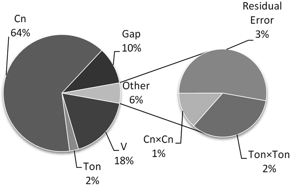
Percentage contribution of factors and interactions on height.
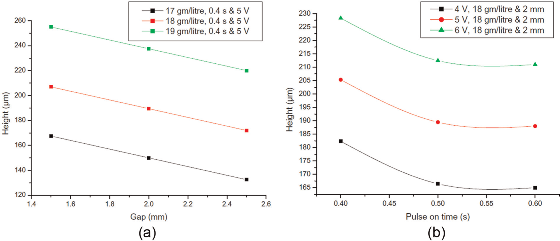
Variation of height with (a) gap and concentration of CuSO4·5H2O and (b) pulse on time and voltage.
Pulse on time is the time for which ultrasonic vibration is given continuously to the electrolyte jet. The ultrasonic vibrations travel through the electrolyte as ultrasonic sound waves. The nonlinear acoustic properties of ultrasonic waves cause streaming in fluids. 3 When ultrasonic waves travel through the nozzle and comes out from the nozzle opening by traveling within the jet, the nonlinear acoustic properties of ultrasonic wave cause streaming. This ultrasonic streaming within the jet causes higher pressure at inner layer of jet compared to the outer layer. This results into increased diameter of the electrolyte jet. Therefore, by increasing the pulse on time, diameter of jet increases. This results in increased area of impinging region, which causes the widening of fabricated parts. The pulse on time does not affect the deposition rates. So this widening of deposition zone results in reduced height (Figure 14(b)) of fabricated feature at same volume of deposition.
Effects of process parameters on wall thickness of fabricated features
The effect of voltage, concentration of CuSO4·5H2O, interelectrode gap, pulse on time and their interaction on width is shown in Figures 15 and 16(a) and (b). A volume (region), in which a positive or negative charge is placed, if force exists on the placed charge, is due to an electric field of that region. Electric intensity or field strength at any point within an electric field is given by the force experienced by a unit positive charge placed at that point 11 following equation (9).

where E is field strength, F is force and C is charge.
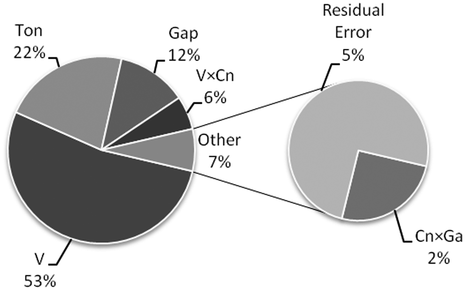
Percentage contribution of factors and interactions on wall thickness.
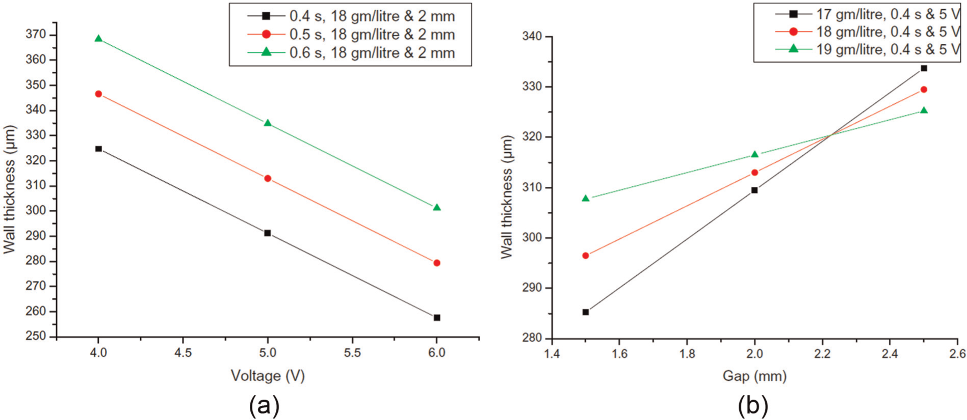
Variation of wall thickness with (a) voltage and pulse on time and (b) gap and concentration of CuSO4·5H2O.
Electric intensity at any point in an electric field is equal to the potential gradient at that point 11 as given in equation (10)
where E is field strength and dV/dx is potential gradient.
From equation (10), it is clear that at higher voltage values, stronger field strength is generated. According to equation (9), this field strength exerts force to the charge. In the present case, this force is exerted on ions, which are moving from anode to cathode. At higher voltage, this increased force causes more streamlined movement along the line of forces. These lines start from a positive charge and end on a negative charge. These lines always leave or enter conducting surface normally. 11 This results in more focused deposition at the impingement region as well as reduced wall thickness, as shown in Figure 16(a). Pulse on time causes widening of the part as explained already in the previous section, also shown in Figure 16(a).
The gap between nozzle and workpiece affects wall thickness. When jet of electrolyte comes out from nozzle opening, it spreads 12 (increase in the diameter of jet) with the distance traveled by it. So if the jet travels more distance to reach the work surface, it will have larger diameter. This results in larger impingement area. At the same time, the field strength inside the jet will reduce according to equation (10). These results in less force exertion on Cu++ ions and wider parts are produced.
The relative permittivity decreases with increasing solute concentrations, that is, concentration of ions. 13 As per equation (11), 11 reduction in relative permittivity results in stronger electric field. In stronger electric field, more focused deposition takes place. But relatively at higher gap, the impact of gap length is overshadowed by this effect (decrease in relative permittivity resulted in more focused deposition) in our range of experiments, as shown in Figure 16(b)
where E is field strength, Q is charge, εr is relative permittivity and dpa is distance from the charge.
Effects of process parameters on side length of fabricated features
Factors affect width (side length) in similar way as they affect the wall thickness. Thicker walls will produce increased width of square-shaped parts for same substrate travel length. The impact of parameters and interactions on width of square-shaped micro part is shown in Figures 17 and 18(a) and (b).
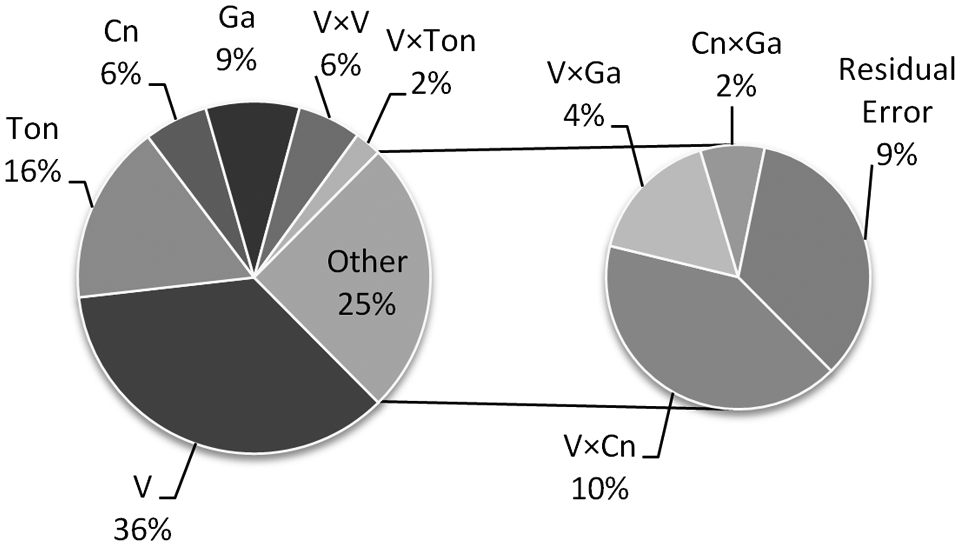
Percentage contribution of factors and interactions on side length.
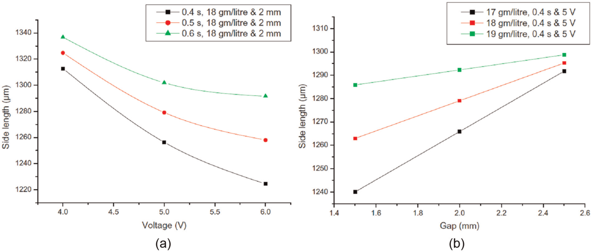
Variation of side length with (a) voltage and pulse on time and (b) gap and concentration of CuSO4·5H2O.
Mechanical properties
Micro hardness of electrodeposited surface and work surface was measured. The work surface was having micro hardness value of 120–130 HV at 50 g load. This is because plate used as work surface was work hardened and alloyed. The micro hardness for electrodeposited surface was found to be 80–90 HV at 50 g load for microstructure, as shown in Figure 9(f), which was at the range of micro hardness of annealed copper. 14 The microstructure size obtained (Figure 9(f)) was in the domain of 40–50 µm, which was also at the range of annealed copper. The high value of micro hardness was obtained because of layer-to-layer deposition of surface and thin layer of deposited surface below which work surface was positioned.
Conclusion
In the present study, copper micro features were successfully fabricated using UAJE. The limitations of HSSJE process like edge effect and inaccurate dimensions of components could be eliminated by application of ultrasonic waves in the electrolyte jet. The reflected ultrasonic waves interact with the new incoming waves and produce complex nonlinear interaction in the region just above the work surface on the jet. This spreads the ions, being deposited in a more uniform manner across the diameter of impinging zone, and results in more accurate, uniform part without any edge effect.
Voltage, pulse on time, concentration of CuSO4·5H2O and gap between nozzle and workpiece are found to be the significant process parameters affecting the accuracy of fabricated feature.
Voltage, concentration of CuSO4·5H2O and gap between nozzle and workpiece were mainly responsible for deposition rate. The ultrasonic acoustic manipulation does not contribute for deposition rate but increase in ultrasonic pulse on time results in the improvement of dimensional quality of the micro part and reduction of edge effect of the part.
Micro hardness value for deposited surface was found to be 80–90 HV.
Footnotes
Appendix 1
Acknowledgements
The authors gratefully acknowledge the support provided by Council of Scientific and Industrial Research (CSIR) New Delhi, India, for carrying out this study.
Declaration of conflicting interests
The authors declare that there is no conflict of interest.
Funding
This study was supported by the Department of Mechanical Engineering, Indian Institute of Technology Delhi, India.