
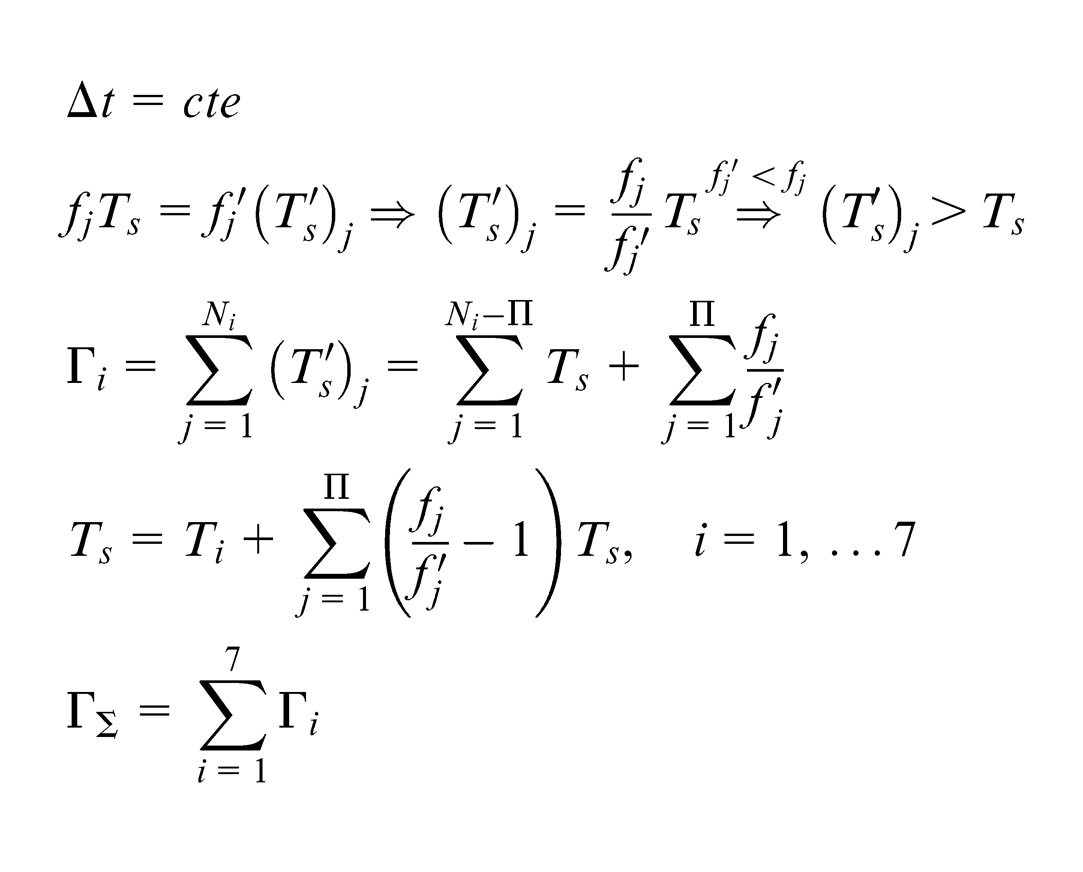
Abstract
The kinematic nonlinearity of the Stewart platform–based machine tools produces a geometrical error which is shown to have significant value compared to the machining accuracy during the interpolation of non-uniform rational basis spline curves and surfaces, thus needs to be limited during the interpolation. In this study, a fast and sufficiently accurate algorithm is presented to estimate the maximum kinematic error based on the concept of the median osculating circle. Moreover, a weighted search interpolator and an adaptive non-uniform rational basis spline interpolator have been introduced, which are capable of controlling and limiting the feedrate fluctuations and limiting the maximum kinematic error within an interpolation segment. The experimental verification has shown the effectiveness of the proposed algorithm.
Introduction
The Stewart platform–based machine tools have found application in machine tools industry since 1990s. This machine also known as hexapod machine tool has six parallel kinematic chains, which provide 6 degrees of freedom for the machine’s table. Contrary to the serial kinematics machine tools, linear motion in hexapod machine tools as parallel kinematics machines is a challenge since their kinematics exhibit nonlinear behavior. This produces machining error especially during the interpolation of parametric free-form curves and surfaces.
The nonlinearity in Stewart mechanisms has already been dealt with to some extent in the literature. Jinsong et al. 1 analyzed kinematic nonlinearity of parallel mechanisms using Bates and Watts measures of nonlinearity. Wang et al. 2 developed an algorithm to predict the interpolation error of a 3-degree-of-freedom parallel kinematic machine based on the singular values of the jacobian matrix. Karimi and Nategh 3 considered the toolpath parameters and their effects on the intrinsic curvature of the actual trajectory of the upper platform (UP) as an index of nonlinearity and the resulting error. The algorithms developed in Jinsong et al., 1 Wang et al. 2 and Karimi and Nategh 3 are computationally so heavy that make it inappropriate for real-time interpolation of toolpaths. Zheng et al. 4 employed middle sampling interpolation algorithm which is fast enough to be used within an interpolation interval. This algorithm limits the error at the middle of the trajectory in the actuators space.
Interpolation of parametric curves and surfaces has attracted much attention in machining of complex parts in many industries such as dies/molds, aviation and automotive. Considerable attempt has been conducted to perform real-time interpolation of parametric free-form curves like B-Spline, Bezier, Pythagorean-Hodograph and the widely used nonuniform rational basis spline (NURBS) curves and surfaces using serial kinematic machine tools. Fleisig and Spence 5 implemented the so-called nearly arc-length interpolation method for five-axis machining. Shpitalni et al. 6 developed the first-order Taylor interpolator using the linear term of the Taylor expansion series. Later on, some researchers employed second-order terms in real time.7,8 Feed correction polynomial has been employed by Erkorkmaz and Altintas 9 and separately by Heng and Erkorkmaz. 10 In a similar fashion, Lei et al. 11 employed a Hermite cubic spline to obtain the inverse length function, which alternatively established an approximate relation of the curve and arc-length parameters. Tsai and Cheng 12 proposed a predictor corrector interpolator. Erkorkmaz et al. 13 reported that if the ratio of the parameter range to segment arc length differs by as small as 5% between consecutive segments, feed fluctuation would become significant. To reduce the fluctuations, they used Newton–Raphson iterative algorithm using the feed-correction polynomial.
It is demonstrated that the truncation of the higher-order terms (HOTs) in the Taylor expansion interpolators brings about undesirable fluctuation in the feedrate due to the inexact estimation of the curve parameter. Such fluctuation deteriorates the surface quality, brings about vibration and force fluctuation. This phenomenon becomes more critical at higher curvatures, where the toolpath becomes highly nonlinear and the HOTs play significant role, and the truncated Taylor expansion interpolators produce erroneous results. It is demonstrated in the literature that the Taylor expansion interpolator’s performance is greatly dependent on the curvature of the toolpath and thus is not robust. Lei and Wang 14 presented a method to improve the robustness of NURBS interpolators. However, their major concern was the extreme knot distribution not the curvature.
To alleviate the shortcomings of Taylor expansion interpolator, a fast and robust interpolator called weighted search method (Weighted Stability Index (WSI)) has been employed in the present investigation to interpolate NURBS curves with limited feed fluctuations. To the extent that the authors are aware, few attempts have been devoted to consider the nonlinearity of the Stewart platform’s kinematics and its effect on the geometrical error during the interpolation of NURBS curves. This has been the motivation of the present investigation to develop a novel adaptive NURBS interpolator for hexapod machine tools for controlling and limiting the geometrical error, which results from the nonlinear behavior of the mechanism. To this end, a fast and accurate estimation model for the kinematic error has been developed and presented, which is suitable for NURBS interpolation.
Evaluation of the kinematic error during NURBS interpolation
Wang et al.
2
concluded that for a 3-degree-of-freedom parallel kinematic machine tool with an interpolation interval of 1 ms and the common speeds, the kinematic error is negligible. However, the orientation of the UP significantly affects its nonlinear behavior. To demonstrate this and make a comparison between the kinematic error during a NURBS interpolation with the level of the machining accuracy, simulation of a sample interpolation segment using forward kinematic solution is presented here. In this example, pods are assumed to move from
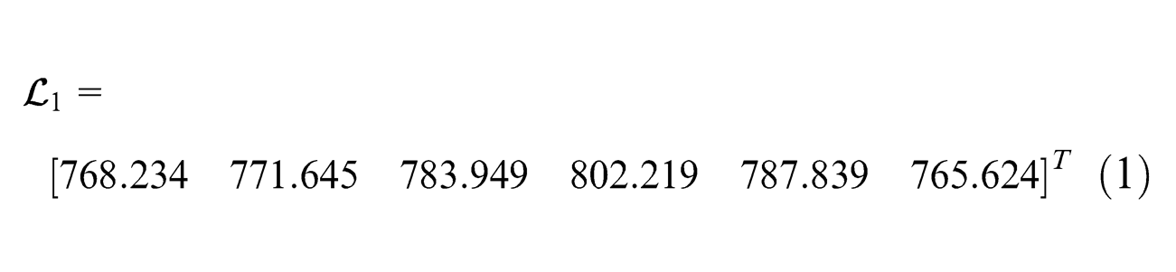
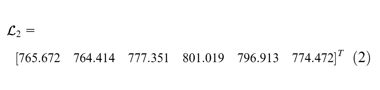
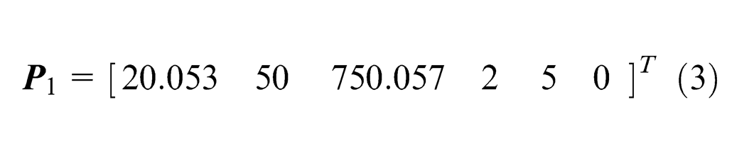
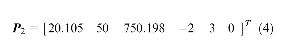
The length of a line connecting
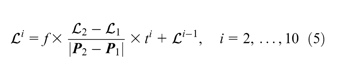
where
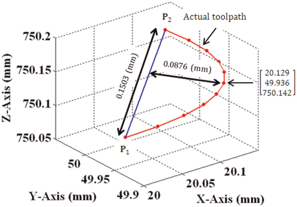
Nonlinear motion of the upper platform.
As it can be seen from Figure 1, the maximum difference between the actual toolpath and the linear one connecting
Modeling the maximum kinematics error using median osculating circle
During the interpolation interval, servo motors are derived with constant speed producing a linear motion of the pods. For such a case, it has been shown in the literature that the actual trajectory of the UP is almost circular. 1 The concept of median osculating circle (MOC) is adopted and employed to estimate the maximum kinematic error.
Assuming that the UP moves from A to B with its pods elongating at a constant speed, MOC is defined to be a circle passing through A and B with its radius equal to the osculating circle at the midpoint of the actual trajectory. MOC as shown in Figure 2 is obtained by moving the osculating circle at the midpoint of the actual trajectory upward such that it intersects both A and B.
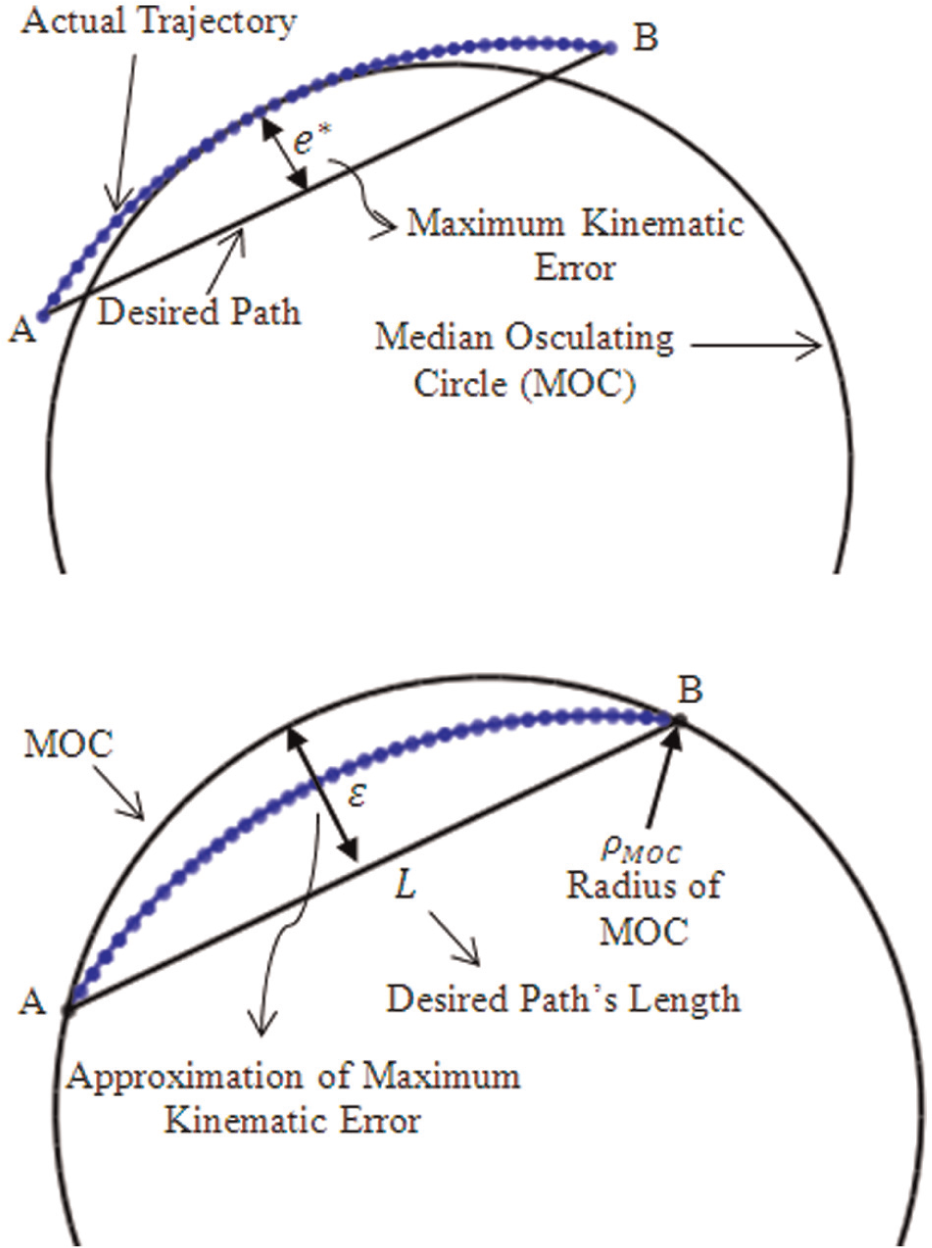
Estimation of maximum kinematic error using MOC.
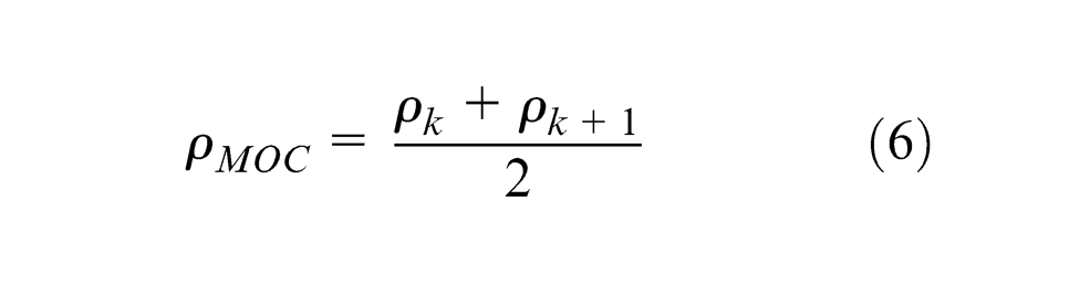
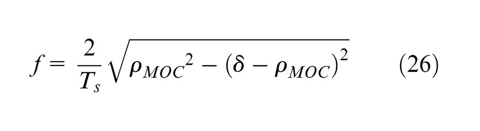
The radius of the MOC (
where
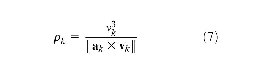
where,
Figure 3 shows the osculating circles at points A and B as well as MOC, which approximates the curve. The maximum kinematic error is also illustrated in this figure.
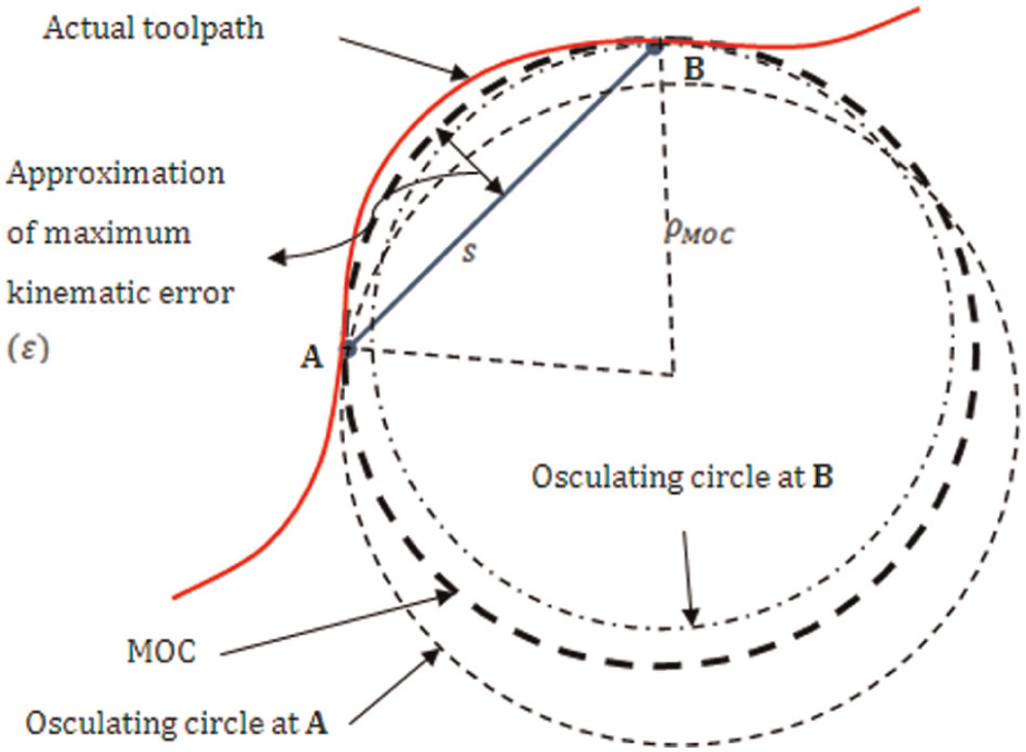
Median osculating circle as an approximation of actual toolpath.
The maximum kinematic error can be obtained as follows
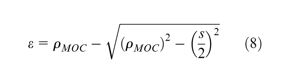
where
Adaptive NURBS interpolator for hexapod machine tools
NURBS formulation
Cox-de Boor recursive is the conventional formulation of NURBS curves and surfaces. Matrix formulation, however, is computationally more beneficial. Cohen and Riesenfeld 16 presented the matrix formulation of open nonuniform nonrational B-Spline curves. Qin 17 and Choi et al. 18 reported that substitution of Cox-de Boor recursive formulation with the matrix one results in less complexity and faster computation. In this investigation, the matrix formulation of open NUBRS is presented. Cohen and Riesenfeld 16 showed that the general form of the mth segment of a periodic nonuniform nonrational B-Spline can be presented as follows
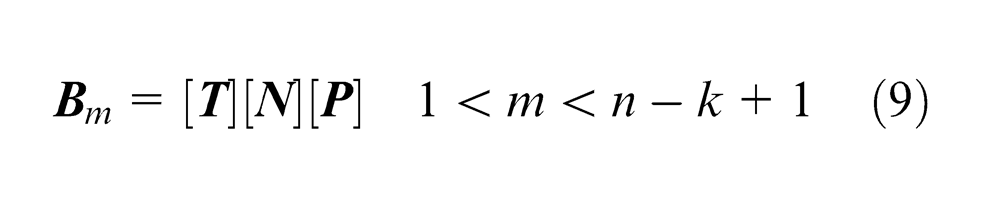
where k is the order of the B-Spline basis function, and there are
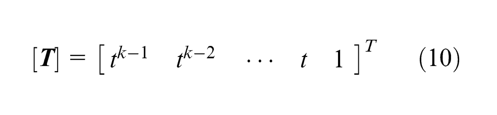
To obtain the vector
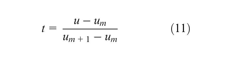
where t is the new curve parameter, and
The elements of
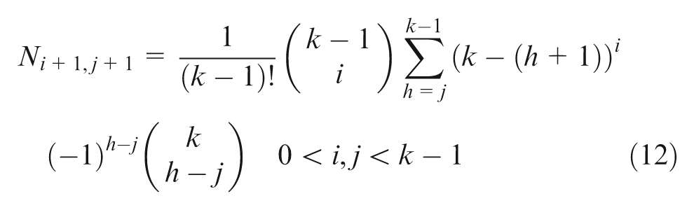
Now the generalized NURBS formula can be represented as follows
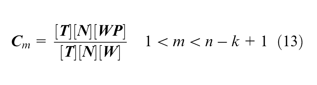
where
and
is the vector of three consecutive weights corresponding to the control points.
Weighted search NURBS interpolator
Taylor expansion is the most widely used method to interpolate parametric curves. The first-order Taylor expansion interpolator described by Shpitalni et al. 6 is computationally fast and thus suitable for real-time interpolation. First-order Taylor expansion interpolator is presented by the following equation
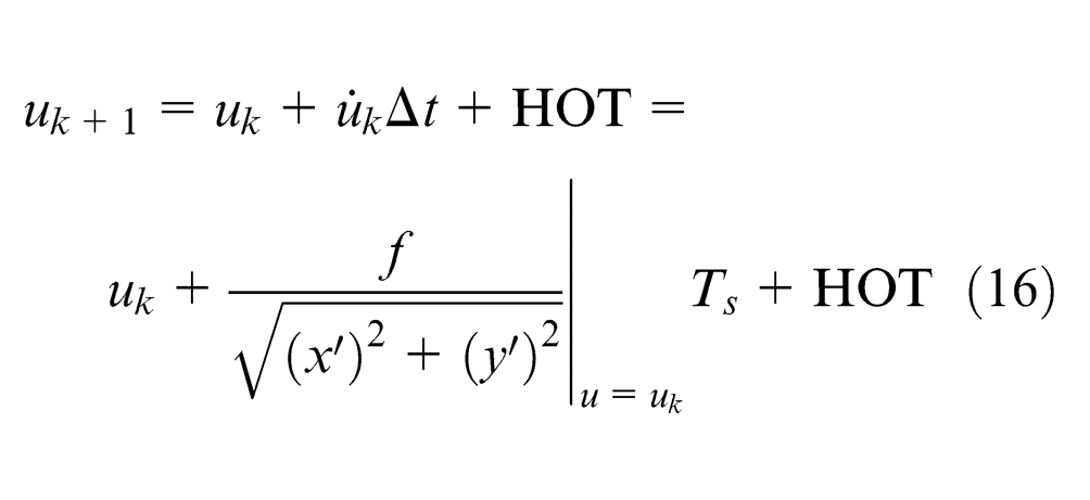
where
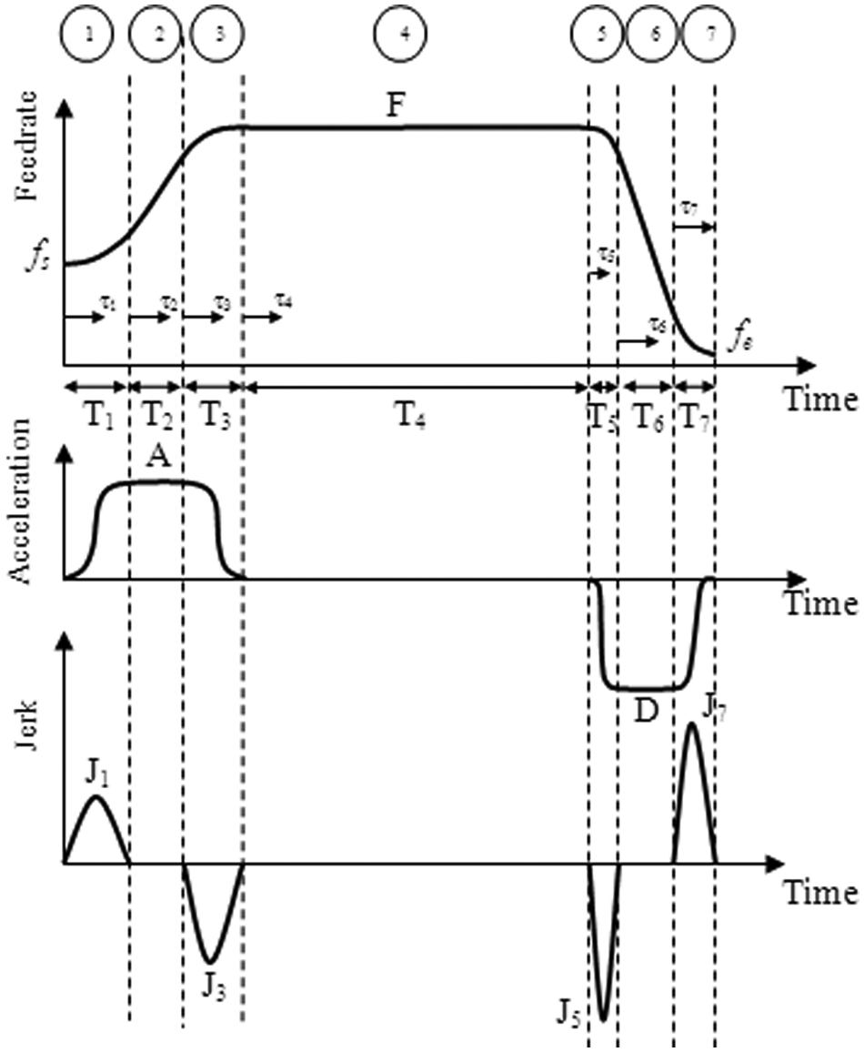
Cubic acceleration kinematic profiles.
The Taylor interpolator fails to follow the feedrate profile as presented in Figure 4 due to the truncation error, and thus, feedrate fluctuation is inevitable. The weighted search interpolator (WSI) is a hybrid interpolator, which is capable of limiting and controlling the feedrate fluctuation. In this method, the next curve parameter is obtained from first Taylor interpolator and is designated by
Feedrate error is evaluated at

If
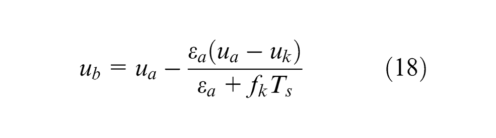
If the condition (19) is not satisfied, then

Using
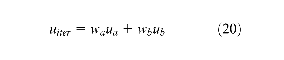
where
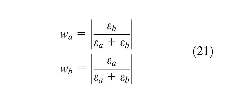
Replacing

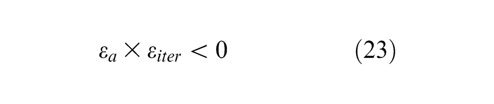
Only one of the above inequalities is satisfied. If equation (22) is satisfied,
Adaptive maximum kinematic error control
As it can be seen from equation (8),
where
The regulated feedrate can be calculated by replacing
Therefore, the equation for the feedrate can be obtained as follows
The modification of the feedrate requires the update of the kinematic profiles otherwise the interpolation would be terminated prematurely as more time is needed to interpolate the toolpath due to the feedrate reduction. To update the kinematic profiles, each time constant (
The time interval
where
Experiments
The hexapod machine, which is employed to conduct the experiments of this investigation, has been manufactured and installed in the advanced technologies of machine tools laboratory at Tarbiat Modares University. This machine is shown in Figure 5. A human machine interface (HMI) has been developed for this machine in Visual C#, which is capable of interpreting the G-code commands based on ISO 6983. This interface also provides the user with the capability of defining NURBS curves and surfaces through setting their control points and the corresponding weights. A motion controller and six servo systems, including servo drives and servo motors implement the commands sent from the interpolator. The adaptive WSI interpolator as described above is implemented via the interpolation module of the machine. The motion controller provides the six servo drives with the appropriate voltage as the servo input command and receives the feedback from the servo encoders to close the position control loop. The velocity control loop is closed in the servo drive. A P-PI controller has been developed for the machine. The P-controller is applied to the position control loop, and the PI controller is applied to the velocity control loop. The system dynamic characteristics are identified experimentally in this research, and the controller gains are tuned correspondingly. The hexapod possesses six universal and six spherical joints. The six universal joints are installed on a virtual circle with the radius of 634.24 mm on lower platform. This radius has been identified after calibration. 20 The angular distance between the universal joints of each pair is 40°. The angular distance between each two adjacent pairs is 120°. The six spherical joints are also installed around a virtual circle on the UP. The radius of this circle identified by calibration is 250.93 mm. The angular distance between the spherical joints of each pair is 85°. Each two adjacent pairs are 20° away. Two cameras were used to measure the position of the UP during its motion. The cameras took a picture from two perpendicular directions from a target installed on UP every 1/30 of a second. The films recorded by the cameras were processed using image correlation function embedded in MATLAB to obtain the location of the target.
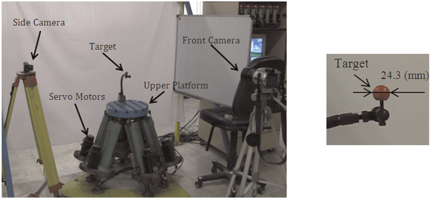
The experimental setup.
Results and discussion
Six different NURBS curves were designed to perform the experimentation. The control points for these curves are shown in Table 1.
The control points.
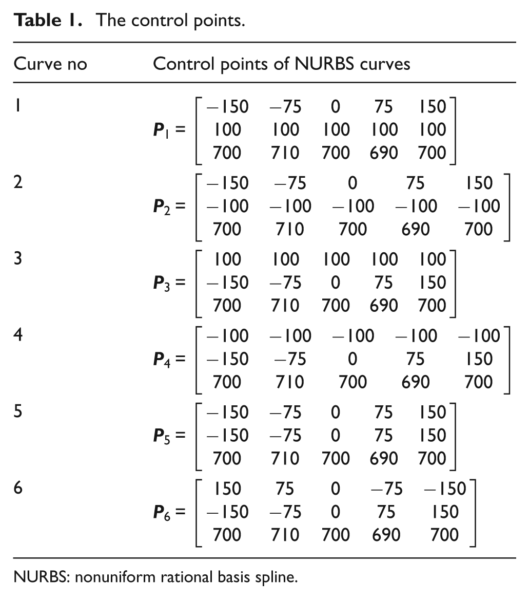
NURBS: nonuniform rational basis spline.
The first and second curves exist on the plane parallel to the
First toolpath
The first NURBS curve before adaptive error control algorithm is shown in Figure 6(a). The control points are given in Table 1, and the weights for each control points are considered to be 1. The interpolated segments are numbered on the figure. A polynomial of degree 6 is fitted to the experimentally measured data to enable comparison between the commanded and the measured toolpaths. The interpolated segments after applying the adaptive error control algorithm are illustrated in Figure 6(b).
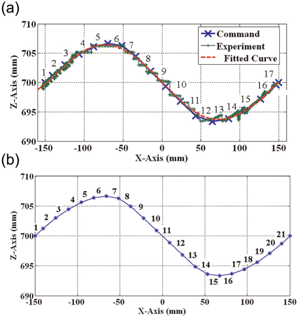
First NURBS toolpath: (a) before adaptive error control algorithm and (b) after adaptive error control algorithm.
As it can be seen from the figure, the number of segments is increased after the adaptive error control algorithm is applied to keep the kinematic error below 0.05 mm. The measured maximum kinematic error for each segment during the interpolation, which is measured by the setup described earlier, before and after adaptive error control algorithm for the first NURBS curve is shown in Figure 7.
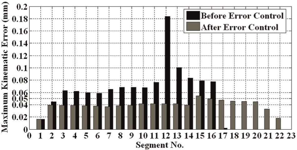
The maximum kinematic error before and after adaptive error control algorithm for the first curve.
As it can be seen from this figure, the maximum kinematic error from the 3rd segment to the 16th one has exceeded 0.05 mm before the error control algorithm is applied. However, after this algorithm, the error is successfully controlled such that it is always below 0.05 mm.
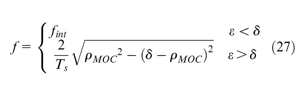
The expense of error control is the reduction in the feedrate as shown in Figure 8. As an instance, it is observed that 260 mm away from the beginning point on the curve shown in Figure 8, the feed is decreased from 20 to 8 mm/s. Such a reduction in feedrate is performed by the interpolator to limit the maximum kinematic error to 0.05 mm based on the algorithm and the formulation presented in section “Adaptive maximum kinematic error control.” It is also evident that the feedrate in Figure 8 is not allowed by the adaptive algorithm to exceed 15 mm/s for this toolpath to keep the maximum kinematic error below 0.05 mm. It should be noted that as equation (27) demonstrates, the feedrate and the maximum kinematic error are interrelated by the radius of MOC, which depends on the curvature of the actual trajectory at the midpoint. The curvature itself varies by the position/orientation of the UP together with the velocity and acceleration of motion as equation (7) shows.
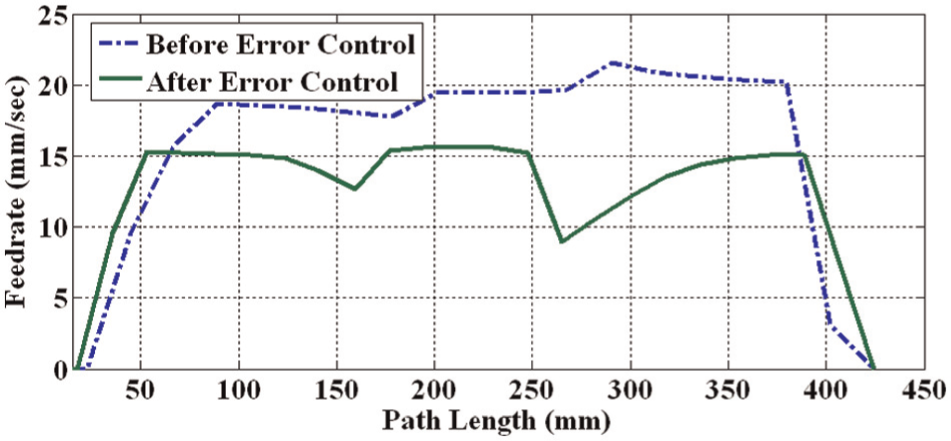
Feedrate before and after error control algorithm.
This figure also indicates that the maximum kinematic error within the 15th segment after error control algorithm is 0.002 mm above the allowable limit (4%). This is due to the approximations considered during the formulation of the proposed algorithm. The maximum kinematic errors at each segment for the rest of toolpaths are shown in Figure 9.
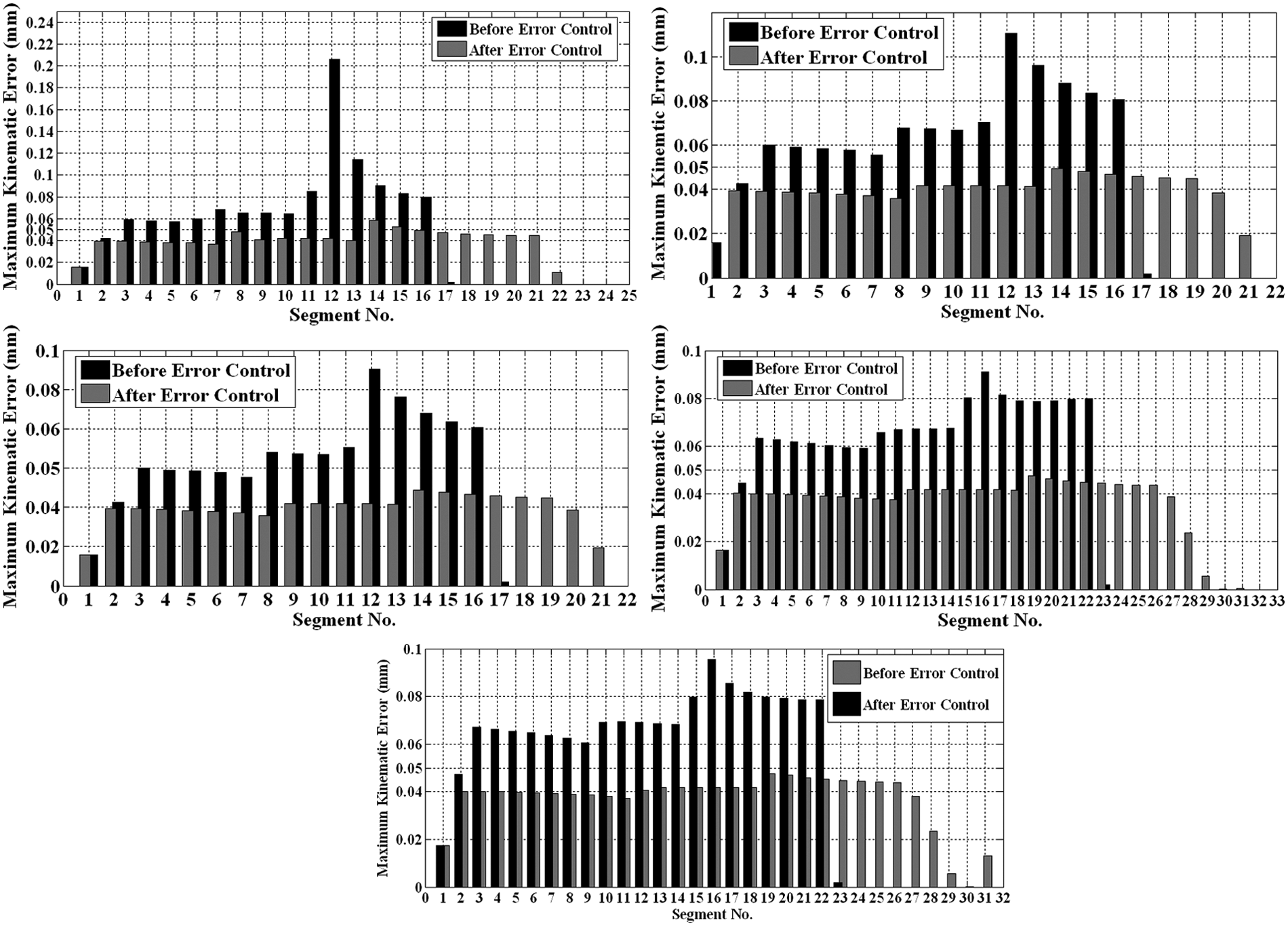
The maximum kinematic error before and after adaptive error control algorithm for curves 2–6.
The effectiveness of the proposed algorithm to control the maximum kinematic error is evident from Figure 9, as the error is limited to 0.05 mm within all segments for all six NURBS curves.
Conclusion
It was shown in this study that the geometrical error produced as a result of kinematic nonlinearity of the mechanism in hexapod machine tools called kinematic error is significant compared to the machining accuracy of NURBS curves and surfaces. It was also mentioned that using the solution of forward kinematics within an interpolation interval is not practical.
A fast method and the relevant formulation were introduced to estimate the maximum kinematic error. The proposed method was employed to develop an adaptive interpolation algorithm. This algorithm calculates an estimation of the maximum kinematic error and regulates the feedrate if the error exceeds its allowable value. The experimental results showed that the proposed algorithm could keep the maximum kinematic error below the allowable specified range along the tested NURBS curves lower than 4%.
Footnotes
Declaration of conflicting interests
The authors declare that there is no conflict of interest.
Funding
This research received no specific grant from any funding agency in the public, commercial or not-for-profit sectors.