
Abstract
This article presents a novel industrially feasible approach to ensure that an integrated optimum configuration of machine, media and geometry is achieved for abrasive flow machining process optimisation. Historically, new part introduction requires a trial-and-error phase to develop a process model, while the proposed method identifies two key explanatory variables (edge form and average roughness) and the process conditions in which they are achieved in testpiece geometry. The method and its shop-floor implementation perspectives are evaluated and verified through computational fluid dynamics simulation and well-designed machining trials, plus reapplied to more complex workpieces. The method can significantly improve abrasive flow machining process capability, accuracy and efficiency and be used to optimise machine design, attempt radical new methods of workpiece fixturing and provide an avenue to incorporate and reanalyse the adaptations of abrasive flow machining machinery.
Keywords
Introduction
Since its inception in the 1960s, the abrasive flow machining (AFM) process has been applied successfully to high-value manufacturing industries for the purpose of polishing, edge-rounding, honing and removal of recast layer. Especially suited to the processing of features inaccessible by hand, production methodology is well established, typically consisting of a single design stage to control the introduction of the abrasive media. With an increasing trend towards harder and tougher workpiece materials and more complex geometry, the limitations of the AFM process are becoming apparent, none more so than in material removal ability and in the flexibility of machine hardware.
In industry, the AFM process is a widely accepted form of edge- and surface-conditioning with primary application in parts with internal cavities inaccessible by traditional hand tools.1–3 A principal concern in the production environment is the accuracy and repeatability with which an engineer can claim to control a process – AFM is subject to multi-order interactions between its (approximately) 25 variables, which dictate the final part condition.4,5 Most of these variables are passively altered (i.e. friction accumulating thermal energy within the media), although there are three key groups of factors, which allow full control, that can be split into machine, media and geometry categories for ease of description. 6
It is universally recognised that trial and error processes in product development are a wasteful, slow and inefficient means of gaining process knowledge and confidence;7,8 in AFM, this is currently a prerequisite to undertaking customer work. It prevents the timely and accurate provision of customer quotations, the economic selection of materials for tooling and media (including subsequent manufacture) and the certainty of a successful outcome. The limited success of the process to date can be explained by the lack of a direct competing technology and the long-term experience of several key players. In order to progress the AFM process beyond trial and error and cope with increasingly complex geometric features and configurations, a new scientific and industrially feasible approach is essential and much needed, so as to automate the selection of parameters in the three key areas and enable the process working in a truly predictable, reproducible and highly productive manner.
AFM suffers from hydraulic system pressure drop, predominantly due to the highly viscous fluids in use, without which the grit (the cutting edge) would have an unsupportive matrix. In oil and gas industry components, some of the most difficult features to process contain holes of 5 mm diameter and 1.6 m length, making the simulation aspect of this technique of critical importance, due to multiple difficult-to-reach features. While computational fluid dynamics (CFD) simulation has been applied previously in simplistic form; 9 the methodology presented in this article is the most complete and industrially viable. Furthermore, the article discusses implementation aspects of the approach in an industrial context, providing the methodology for the integration of simulation in a greater role as a means of determining edge profile and surface roughness in the optimised AFM process.
Process factors and interactions
Control of the AFM process is restricted to modification of the variables categorised within machine, media and geometry groups, as shown in Figure 1. 6 Within machine, the engineer has four options: velocity, stroke, temperature and cycles. Within media, the engineer has four options: grit size, carrier viscosity, grain fraction and percentage of filler. Within geometry, the engineer has free reign over additional tooling, but no control over customer component geometry – this leaves part cross-sectional area, part volume and pressure drop only within partial control, but nevertheless as an independent variable. Key to providing a repeatable and stable processing environment is to ensure that parameters operate within a tolerable range, which is achieved by correct sizing of components in the system. The machine in use at Mollart Engineering Ltd is a Micro Technica Technologies ‘Duplex 250D’; a 4.4 kW hydraulic motor delivers a total of 47 bar (4.5 MPa) maximum allowable working pressure (MAWP). At this limit, heat accumulation is rapid and spreads quickly – this affects other elements of the system, in particular the viscosity of the media. As an end user, machine modification is a last resort, preferring changes to media formulation and tooling to avoid excessive pressure requirements.
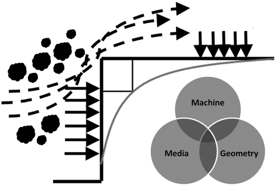
Schematic of square-edge testpiece geometry under conditions dictated by machine, media and geometry variables.
Data collection exercises
An experimental design is proposed to create two datasets, both specific to a given testpiece geometry and material. A three-level design is proposed to model possible curvature in the response function and to handle the case of nominal factors at three levels. Three repetitions of each trial are recommended, totalling 81 runs for each dataset. The first treats the workpieces to variations of machine parameters; velocity, temperature and length are the independent variables under consideration. Media is held constant as a control. The second dataset is formed by treating the workpieces to variations of media parameters; grit size, grain fraction and viscosity are the independents in this test. Support is received from a subcontractor in the field of product formulation in order to develop the different media required. Throughout each experiment, the testpiece and tooling must remain the same geometry and material.
The first explanatory variable of system performance is surface roughness – using a white-light interferometer (WLI) (Zygo NewView 5000), four points of average roughness (Ra) are collected from along the testpiece surface. Surface roughness is a function of the machine and tool used to create the surface initially – AFM offers greater improvement in Ra where preprocess Ra is worse and grit size in use should determine ultimate Ra. Testpieces are manufactured from a Ø16 mm bar and have a milled 10 mm2 section, as shown in Figure 2, which allows for preprocess and post-process data collection, providing an accurate ΔRa value.
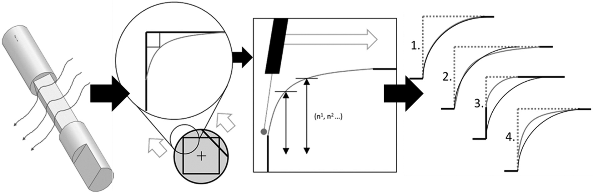
Testpiece form and flow direction (left), formtracer measurement technique (centre) and potential radius forms (right).
The form of the edge after processing will be paired with flow path sections from CFD-based simulations. These data, coupled with processing length information, will be useful for determining expected material removal and location of material removal. Data are collected by means of a Mitutoyo CV series Contracer, as illustrated in Figure 2. The testpieces will be measured for form after roughness measurement to avoid scoring the substrate. Tangentially formed radii are not a foregone conclusion – they are difficult (although not always necessary) to achieve; therefore, a single value for edge form cannot be recorded – data collected from this instrument will form the mainstay of CFD-based simulations for evaluation and verification.
Interpretation, analysis and reapplication of simulation and experimental data
As depicted in Figure 3, a novel methodology is proposed to tackle the setting-up of the AFM process with greater precision. Customer requirements are an input, alongside data collected in two large-scale experiments describing the effects of varying machine and media parameters. This provides an engineer with ‘target’ conditions (a pressure, velocity, temperature and media formulation) that he or she must impose upon the point of interest (POI) in order to achieve a specific result – a result known to be conducive to a desired roughness or material removal profile. Once these values are chosen (based upon previous experience in the specific workpiece material), basic fluid dynamics principles are employed to estimate the machine parameters necessary to deliver the required conditions at the POI. As these conditions are only relative to the testpiece geometry, CFD-based simulations are employed to extend the results of the two studies into parts that have not yet been physically processed.
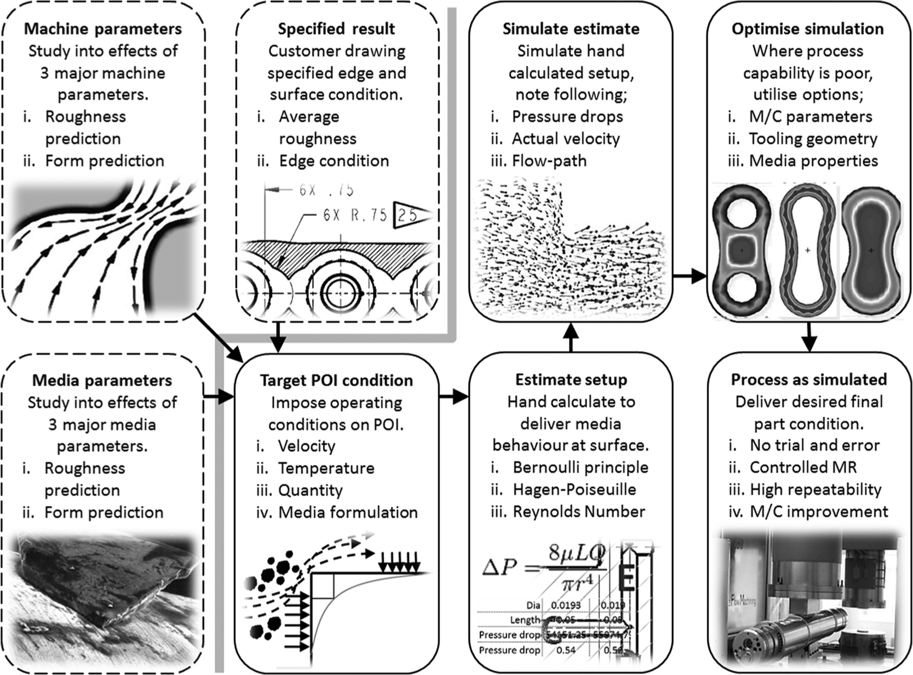
Integrating simulations as a means of process outcome prediction for complex geometry.
As the number of features increases, their position relative to one another becomes more asymmetrical and fluid behaviour increasingly difficult to calculate by hand, making the application for CFD-based simulations clear. As the machine delivers a constant force, the media travel at the speed permitted by the volume of the cavity being processed. In order to rectify the velocity to achieve uniform processing, we introduce an additional layer of tooling (such as plugs, diverters and sheaths) – this may be used to increase the velocity at a given point with the trade-off of pressure drop, all of which is infinitely trialled in silico. In a production application, a solid model of the part to be processed will be required. The engineer will run a full simulation of the component installed on the machine, within which confidence is held due to the ‘first-principles’ verification of physical processing results of the testpieces. The optimum tooling, media and processing conditions can then be designed and planned for the production in a truly predictable, reproducible and highly productive manner.
Existing knowledge of the AFM process is highly fragmented, as the literature shows research carried out in select workpiece materials, with select treatments and select media configurations, none of which are replicated elsewhere. While we may partially understand a general effect of a parameter alteration, we certainly cannot quantify it with respect to the hundreds of other potential variables. The benefit of using CFD-based simulation is that it cancels out every variable in the geometry corner of the AFM triangle. The simulation-based approach takes measured results of the physical experimental set-up and simulates them using existing fluid rheological behaviour input methods. The simplicity of the testpiece geometry allows hand-calculated verification of parity in terms of strain rate, velocity, pressure and temperature between physical and virtual examples for all 27 unique combinations. This allows simulations on the model and further evaluation and validation, as illustrated in Figure 4, which shows the simulated and experimental machining trials for average surface roughness and material removal in reasonable agreement as progressed so far. The engineer now has the knowledge of testpiece surface conditions and resultant surface roughness and material removal rate for a given media and material – we can then work backwards for an arbitrary workpiece geometry using the optimal process variables and set-up derived through simulation.
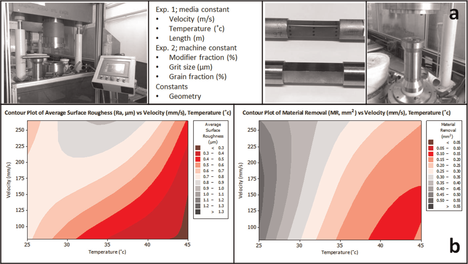
(a) Experimental machining and (b) results on validating the model and simulations in terms of surface roughness (left) and material removal (right).
Conclusion
This article presents a scientific-based industrially feasible approach to AFM process optimisation, which integrates the CFD simulations on accurate AFM fluid behaviour with data collected from rigorously structured and verified machining experiments. The approach and associated techniques can significantly improve the AFM process capability, accuracy and efficiency. As a powerful tool and method, it opens the process up to new inexperienced users by increasing the ability to forecast tooling costs, processing time and consumables usage. In further applications, the technique can be used to optimise machine design, attempt radical new methods of workpiece fixturing and provide an avenue to incorporate and reanalyse adaptations of AFM machinery.
As an automated approach to the trial and error prerequisite problem, the methodology presents a highly useful and valuable technique for determining the correct processing conditions for a given set-up. The CFD simulations are applied in order to transfer the data collected in simple geometries to the increasingly more complex workpieces in the production environment. The proposed approach enables the AFM process to be operated in a truly predictable, reproducible and highly productive manner, although it is still under further development for complex components in difficult-to-machine materials such as Titanium and Inconel alloys.
Footnotes
Declaration of conflicting interests
The authors declare that there is no conflict of interest.
Funding
This study was supported by UK Technology Strategy Board (grant number 710231) and the UK Engineering and Physical Sciences Research Council (EPSRC) for the EngD Scholarship.