
Abstract
Burr formation and edge finishing are research topics with high relevance to industrial applications. To remove burrs, however, a secondary operation known as deburring is usually required. Deburring is more complex and costly when dealing with milled parts, because multiple burrs form at different locations with various sizes. Therefore, proper selection of process parameters to minimize the burr size is strongly recommended. Therefore, this requires an understanding of milling burr formation mechanism and the governing cutting parameters on milling burrs. In this article, a multilevel experimental study is arranged to investigate the effects of machining conditions, tooling and workpiece materials on burr size (height and thickness). Statistical tools are then used to determine the dominant cutting parameters on burr size and to effectively prescribe an operational window to control and minimize burr formation. It was found that optimum setting levels of process parameters to minimize each burr are different. The analysis of results shows the significant effects of cutting tool, feed per tooth and depth of cut on slot milling burrs.
Introduction
As manufacturing processes become advanced, precision components require more attention for both surface and edge generation. More precise and burr-free components with tight tolerances and better surface finish are being requested. This is especially true in the aerospace and automobile industries. Most of all numerous traditional and nontraditional manufacturing processes generate burr. Burrs forming during machining is defined as projections of material beyond the workpiece limits. Gillespie and Blotter 1 distinguished four types of burrs as follows: Poisson burr, Rollover burr, Tear burr and Cutoff burr. Later, various aspects of burr formation problem were addressed by researchers. 2 Deburring operations are expensive, time-consuming and considered as non-productive operation. As pointed out by Gillespie, 3 deburring and edge finishing of precision components may constitute as much as 30% of the cost of finished parts. In addition, the secondary finishing operation is difficult to automate, thus may become a bottleneck in a production line. 4 Presently, more than 100 deburring methods have been developed. 3 The selection of suitable deburring method depends on many factors, including the locations, shapes and dimensions of the burrs. Therefore, for optimal selection of deburring method, the burr formation and size must be controlled. It is extremely beneficial to limit burr formation rather than deburring them in subsequent finishing operations. One approach is to develop analytical models of the burr formation process. This requires a clear understanding of the formation mechanism that can be achieved based on experimental observations of burr development process. Since theoretical approaches are usually not available, more focus has been paid to experimental studies to identify the effects of cutting parameters on burr formation.
Among machining operations, milling burr formation has a more complex mechanism, where burrs are created when the cutter enters and exits the machined part. Nakayama and Arai 5 classified milling burrs based on the cutting edge and by the mode of direction on burr formation mechanism (see Figure 1). The effects of numerous process parameters on face milling burrs were reported in several studies.6–14 To identify the large and small burrs that form on the component edge, the terms “primary burr” and “secondary burr” were introduced by Kishimoto et al. 13 They 13 stated that secondary burrs are smaller than depth of cut, while primary burrs are larger. Chern 14 analyzed burr formation in face milling of aluminum alloy (AA) and found that secondary burr formation is dominated by depth of cut and feed rate. Furthermore, most of the existing research works in literature characterize the burr height, while according to deburring perspective, the thickness of the burr is of interest because it describes the time and method necessary for deburring a workpiece. 2 In addition, only few studies used statistical analysis to precisely determine the dominant process parameters on burr size.15,16
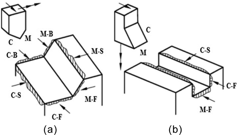
Classification of milling burrs based on cutting edge and by the mode of direction on burr formation mechanism: (a) face milling and (b) slot milling.
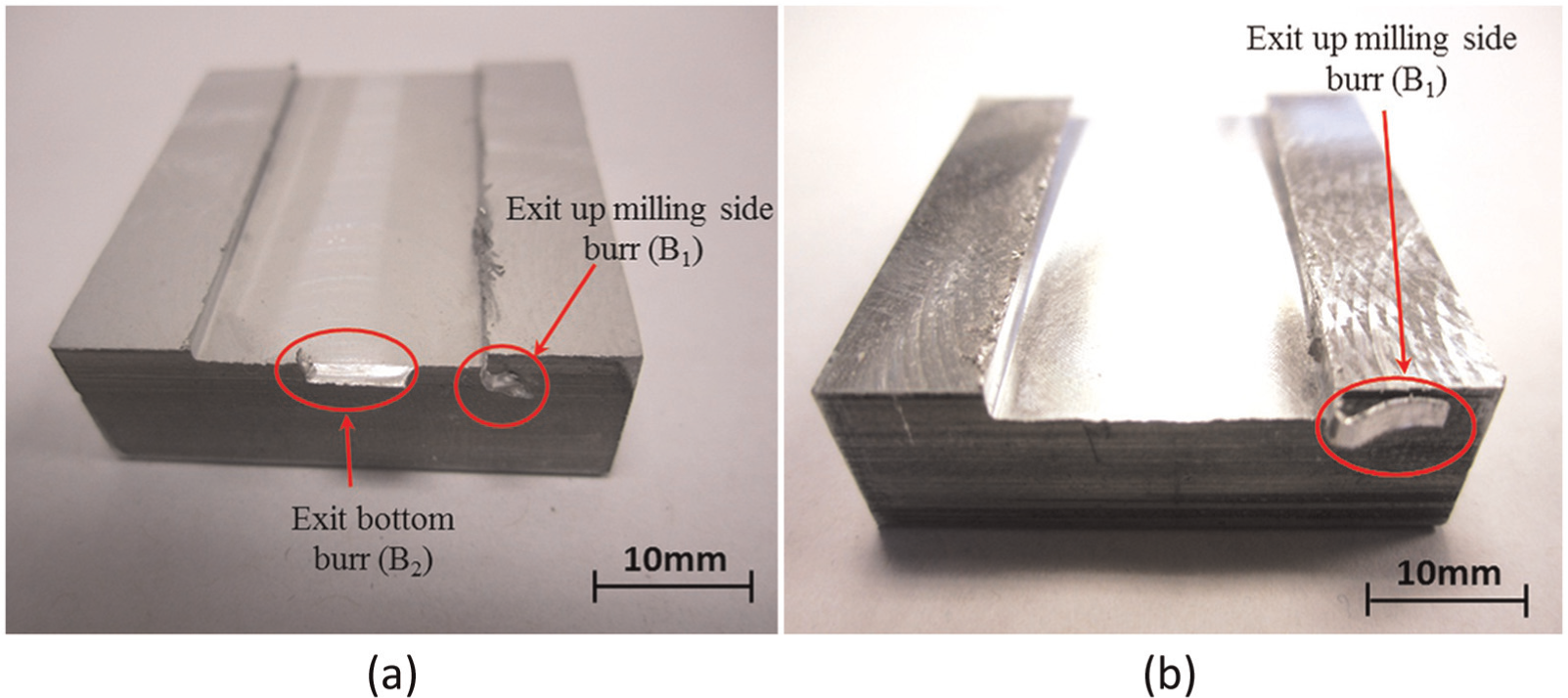
As per author’s knowledge, surprisingly except few works,16–21 very low volume of information is available about dominant process parameters on slot milling burrs. This might be due to the complex nature of slot milling burrs, which their formation mechanism involves three modes with various shapes and geometries as feed direction burrs (entrance and exit burrs), sideward and cutting direction burrs, which appear in eight edges of the machined part (see Figure 2). Unlike in face milling, subsequent tools passing through do not usually remove the burrs produced by previous tools in end milling. Accordingly, side burrs and top burrs can also remain stuck on the part, possibly leading to several problems.
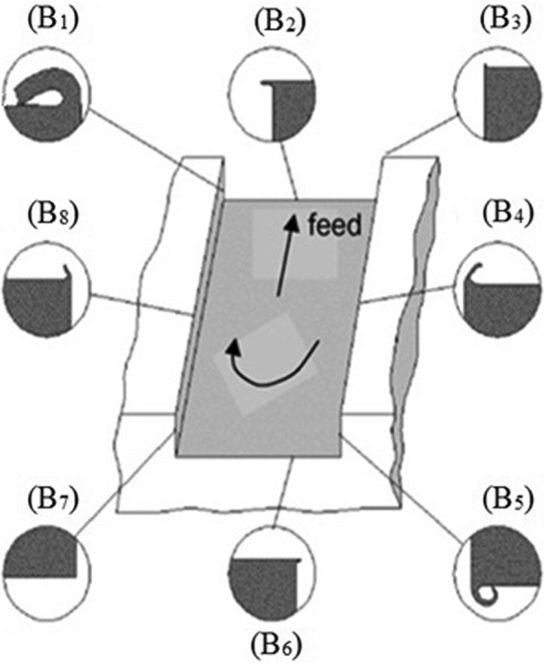
Slot milling burrs.
Entrance side burr along up milling side and entrance bottom burr have the smallest size. The top burrs along up/down milling sides, entrance side and exit bottom burrs along down milling side are on a medium scale, comparatively. The exit side burr along up milling side and exit bottom side burr are the largest slot milling burrs. 14
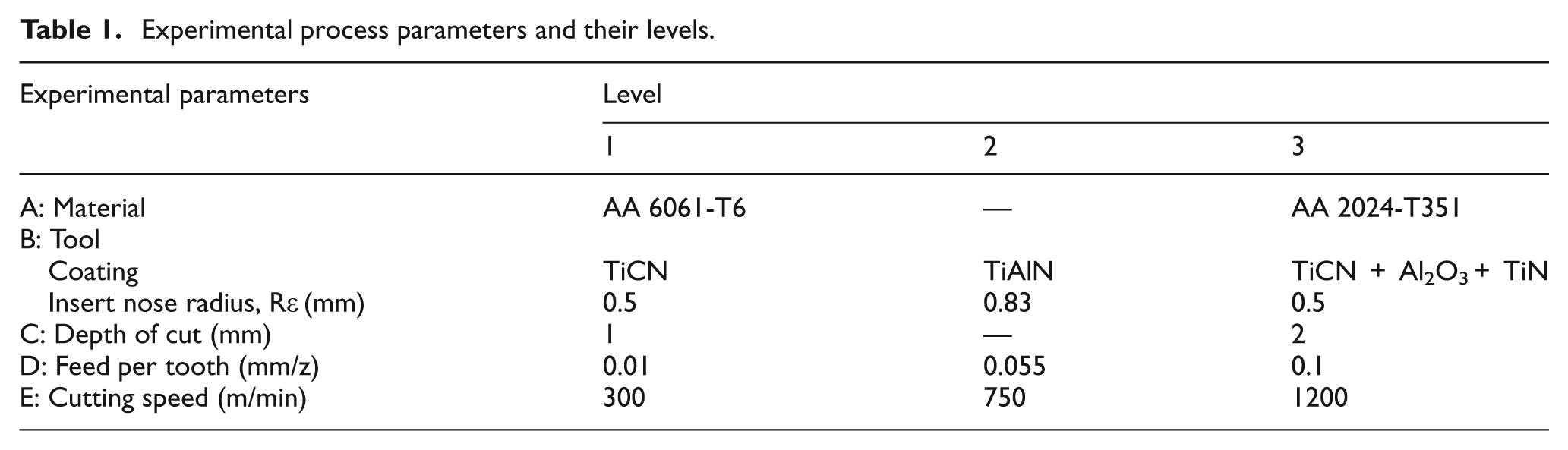
In this study, the burrs on exit up milling side (B1), exit bottom (B2), top side along up/down milling sides (B4, B8) and entrance down milling side (B5) will be studied (see Figure 2). Statistical tools and experimental study in the form of multilevel full factorial design of experiment (see Table 1) are used to characterize burr formation in slot milling of AA 2024-T351 and AA 6061-T6, which are commonly used AAs in aeronautical and automotive industries.
Experimental process parameters and their levels.
The main objectives of this article are first determining the individual and interaction effects of process parameters, which affect mechanism and the dimension of slot milling burrs, and second designing an efficient approach for burr avoidance and/or burr minimization.
The experimental procedure is presented in section “Experimental procedure,” followed by results and discussion in section “Results analysis and discussion.” This study is concluded in section “Conclusion.”
Experimental procedure
A multilevel full factorial design of experiment (33× 22) is selected in this study. The AA 6061-T6 and AA 2024-T351 with relatively similar mechanical properties are used for experiments (see Table 2). The experimental factors and their levels are shown in Table 1. Cutting tool and workpiece materials were treated as qualitative factors, while other remaining factors were considered as quantitative. In total, 108 experiments were performed under dry milling using a three-axis computer numerical control (CNC) machine tool (power: 50 kW; speed: 28,000 r/min; torque: 50 N m), coated end milling cutting tools with three flutes (Z = 3), and tool diameter (D) 19.05 mm.
Typical mechanical properties of studied aluminum alloys.
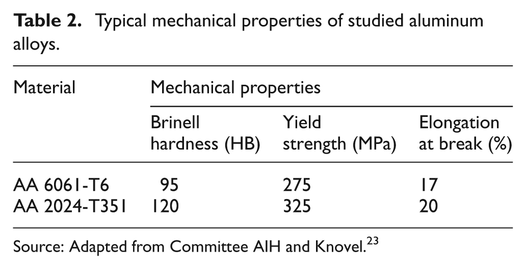
Source: Adapted from Committee AIH and Knovel. 23
An optical microscope equipped with high-resolution camera was used to take the burrs images. The burr size measurements were then conducted on captured images. To measure the burr height, the microscope was focused on the plane of the workpiece exit surface and then on the plane of the top surface of the burr. Focusing on the plane of the parent material, burr thickness image was captured. An average of four burr thickness (Bt) readings and maximum value of burr height (Bh) were taken as the burr size in this study.
Assumptions
It must be noted that machining of AAs cannot be carried out without a certain amount of difficulty. These materials tend to adhere to the tool surface, and burrs are formed inside the holes and at the top of machined part edges. 22 Therefore, to develop the experimental setup, the following assumptions are made:
The slot milling operations are assumed to be chatter free. Vibrations, machine and tool dynamic behavior are not considered. This condition was fulfilled by carrying out preliminary tests and checking the stability of cutting process.
The deflections of the tool and workpiece are assumed negligible. This condition was fulfilled using rigid tool and workpiece fixtures.
New inserts were used after each cutting test to avoid possible deviations in experimental results due to tool wear.
Results analysis and discussion
Burrs can be excessively large and irregular (see Figure 3(a)) or very small in size, even not visible for naked eyes (see Figure 3(b)). Therefore, a proper understating of burr formation mechanism and correct selection of cutting parameters’ setting levels is recommended to reduce the incidence of burr formation and possibly improve the surface quality and tool life. In the following sections, burr formation over top, entrance and exit sides of slot milled parts will be extensively studied.
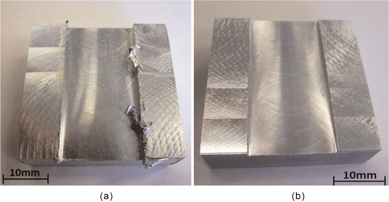
Slot milled machined parts with (a) large burr formation and (b) burr formation with tiny scales.
Method of analysis
In analyzing the quality index parameters of machined parts (e.g. burr size, surface roughness), the use of statistical techniques plays a prominent role. 24 The following statistical terms are used in this article for statistical analysis.
Pareto analysis. A Pareto chart compares the relative importance and statistical significance of the main and interaction effects between process parameters with a 95% confidence interval. Reading the Pareto charts, the predominant role played by each cutting process parameter and their interactions can be identified.
Main effect plot. The analysis of mean is used to determine the optimal process parametric settings by estimating the main effect of each parameter, which is presented in the main effect plot diagram.
Interaction effects analysis. Presents the interaction effects between process parameters.
Exit burrs
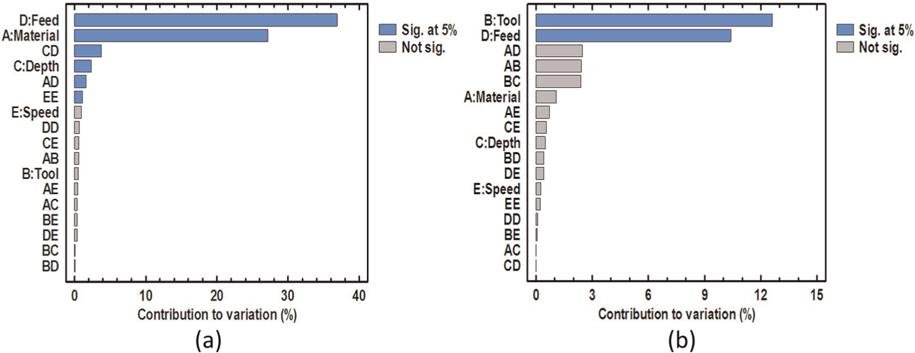
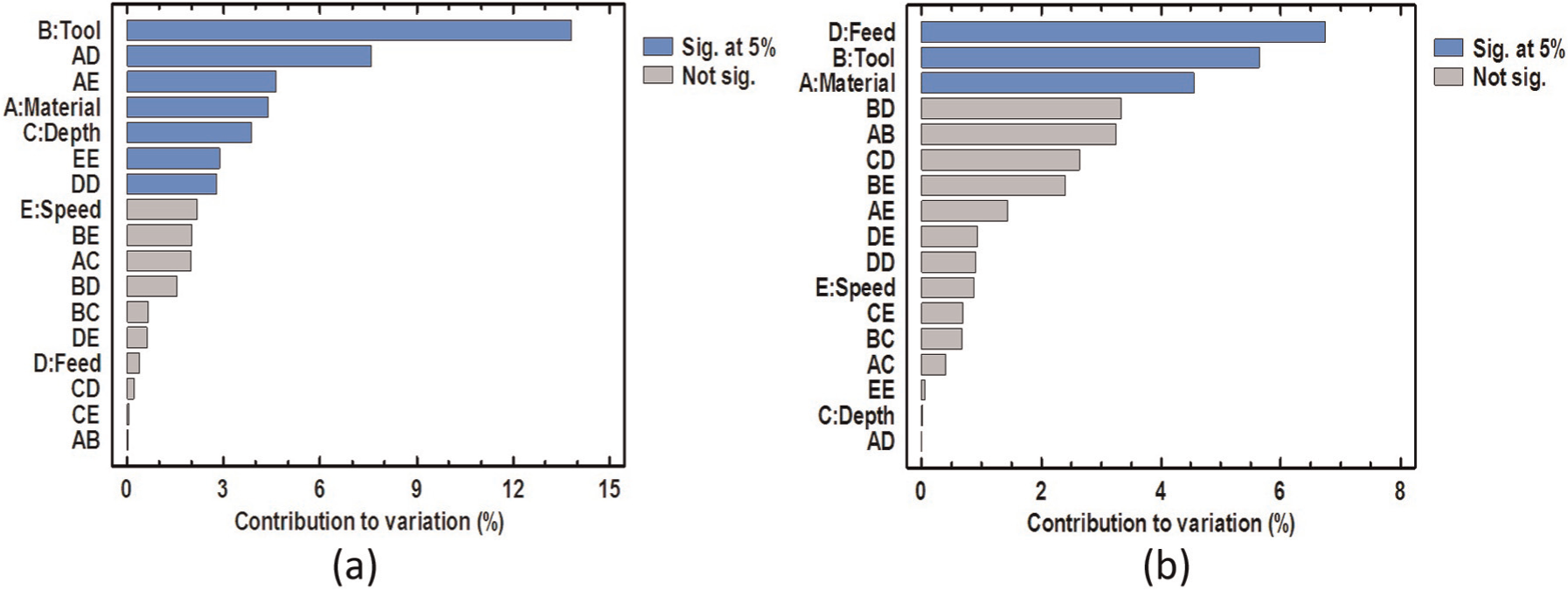
Figures 4 and 5 present standardized Pareto charts of exit burrs. As can be seen in Figure 4, both B1 height and thickness are controlled by feed per tooth (D). According to Figure 4(a), B1 height is influenced by interaction effects between cutting tool and depth of cut (BC), depth of cut and feed per tooth (CD), feed per tooth and cutting speed (DE) and depth of cut and cutting speed (CE), followed by direct effects of feed per tooth (D), workpiece material (A) and depth of cut (C). According to Lauderbaugh, 25 yield strength (σe) is the main material property with significant effects on exit burr formation.
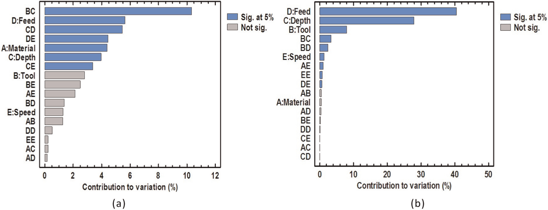
Pareto chart of (a) B1 height and (b) B1 thickness.
Pareto chart of (a) B2 height and (b) B2 thickness.
As presented in Figure 4(b), there are several direct and interaction effects between cutting parameters affecting the variation of B1 thickness. Among them, direct effects of feed per tooth (D), depth of cut (C) and tool (B) are the most dominant factors.
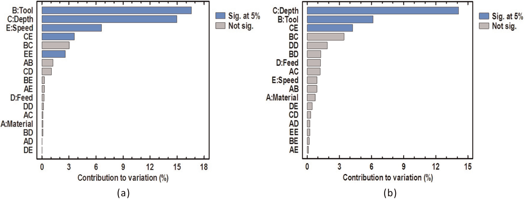
According to Figure 5(a), the B2 height is affected by direct effects of depth of cut (C), cutting speed (E) and tool (B), caused by tool coating and insert nose radius (Rε). The interaction effects between depth of cut and cutting speed (CE) and cutting speeds (EE) are also significant parameters on variation of B2 height. Contrarily, based on Figure 5(b), the governing factors on B2 thickness are direct effects of depth of cut (C) and tool (B), followed by interaction effects between depth of cut and cutting speed (CE).
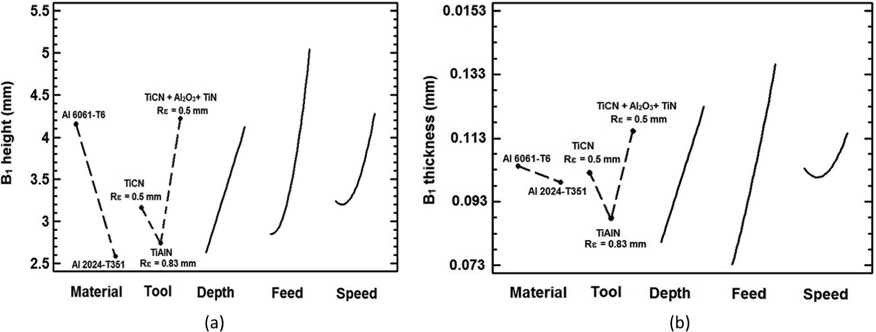
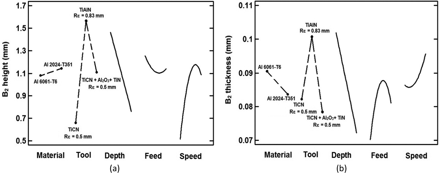
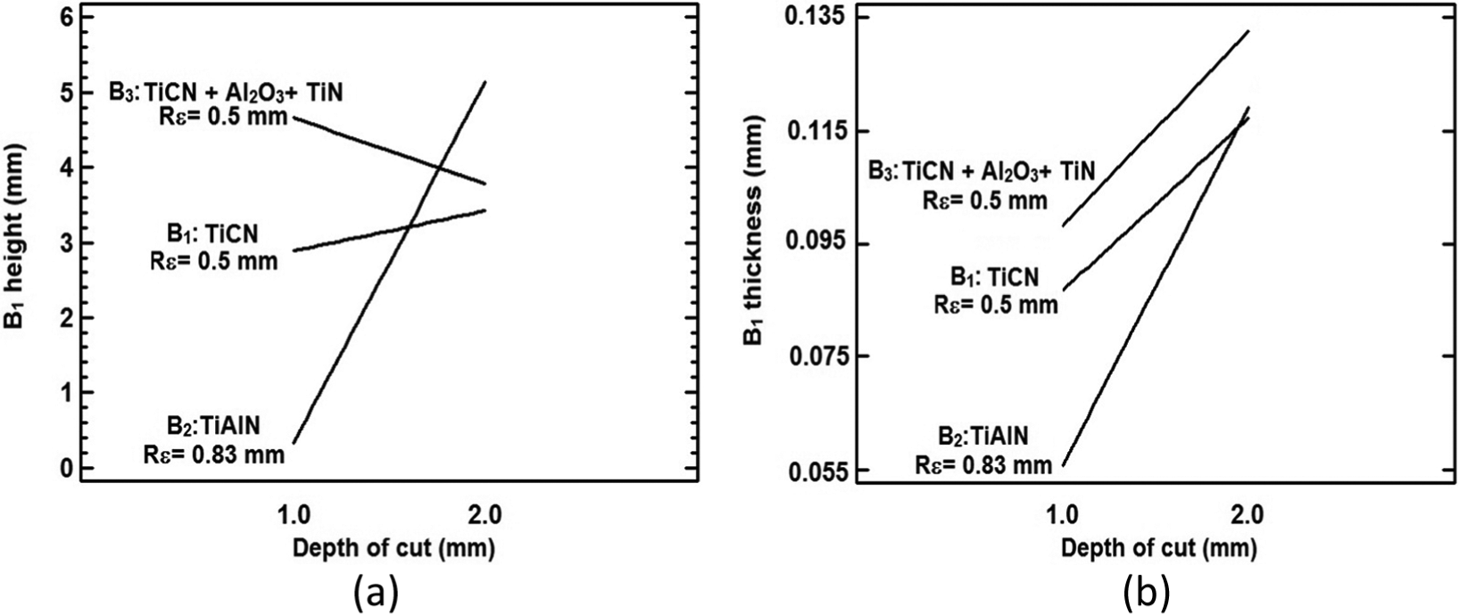
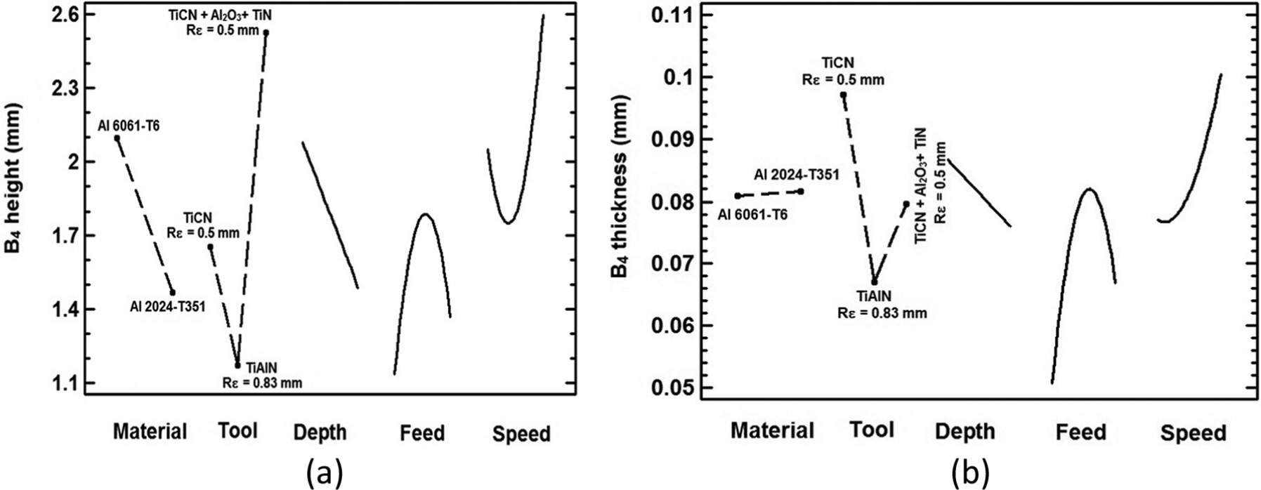
As illustrated in Figures 6 and 7, milling tests with higher levels of feed per tooth and depth of cut and smaller insert nose radius (Rε) led to longer and thicker B1 and shorter and thinner B2. As it is evident from Figure 6, variation of cutting process parameters has a similar influence on B1 height and thickness.
Direct effect plot of (a) B1 height and (b) B1 thickness.
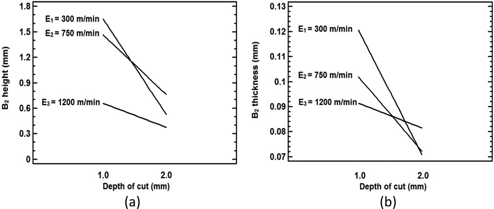
Direct effect plot of (a) B2 height and (b) B2 thickness.
In metal cutting, feed rate, depth of cut, cutting speed and tool geometry are the main controlling parameters. 10 In order to comfort deburring operation, milling burr size minimization can be conducted by facilitating the transition of primary burrs to secondary burrs. This phenomenon may occur when the burr leans preferentially toward the transition material and breaks off from the machined surface. In such a case, side burrs formed instead of exit bottom (B2) or entrance bottom (B6) burrs.
According to face milling burr formation mechanism, exit bottom burr (B2) is formed by loss of material from the exit up milling side (B1) burr. 26 Assuming that face milling burr formation mechanism appears in the exit side of slot milling, transition from primary to secondary burr formation is observed on the exit side burrs along up/down milling (B1 and B3) as shown in Figure 8. When transition from primary to secondary burr formation is not correctly done, primary exit bottom burr (B2) appears in the exit side, when tool leaves the machined part (see Figure 8(a)). When burr smoothly leans toward the transition material and breaks off from the machined surface, then longer B1 and shorter B2 are resulted (see Figure 8(b)). According to slot milling burr formation mechanism and by considering a negligible B3 size, it can be stated that trials to reduce the B2 size led to longer B1 (see Figures 6 and 7).
Slot milling exit burrs.
The first considerations of burr formation in metal cutting came along with investigations about chip formation, as burr formation mechanism highly depends on chip formation mechanism. In milling operation, the chip thickness h(ϕ) varies periodically as a function of time-varying immersion angle (ϕ) as

where fz is the feed per tooth that can be presented as follows

where fr is the feed rate and Z is the tool teeth number.
Tangential force Ft(ϕ), radial force Fr(ϕ) and axial force Fa(ϕ) can be represented by using the specific cutting force coefficients K in each direction as follows
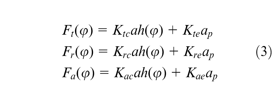
where ap is the depth of cut.
The coefficients Ktc, Krc and Kac are the directional specific cutting force coefficients. The coefficients Kte, Kre and Kae are the specific edge cutting force coefficients. According to equations (1–3), increase in feed per tooth and depth of cut increases directional forces. However, in slot milling, the magnitude of tangential force Ft is greater than the radial force Fr, when the tool leaves the workpiece. In addition, a significant role is played by friction in milling burr formation in exit side, which itself is a function of Ft and Fr. The effect of friction can be divided into three basic mechanisms: (1) due to asperity deformation, (2) due to adhesion and (3) due to particle plowing.
In orthogonal milling, friction coefficient (µ) can be approximated as 27

According to equation (4), when the friction at tool faces decreases, there is a corresponding increase in the shear angle (Φ) and accompanying decrease in the chip thickness h(ϕ). Thus, the plastic strain associated with chip formation is reduced. This will result into longer and thicker B2 and shorter and thinner B1. Increase in the cutting speeds and insert nose radius (Rε) increase the Fr to a large extent, particularly where depth of cut is smaller than insert nose radius (Rε). In addition, materials with higher machinability generate larger Fr, which may lead to a reduction in friction occurred between the chip and tool. 27 Furthermore, during milling operation, slight plastic deformation, serious rubbing and plowing effects appear, which therefore lead to heat generation and increase in the burr size, especially during high-speed machining.
When using tools with multiple teeth, some heat is produced, especially during high-speed machining. This yields to tearing off a part of the burr that accumulated on the top side of the workpiece. This part finally sticks to the side face of the machined part and consequently turns to a burr. However, as depicted in Figures 4 and 5, the cutting speed has statistically negligible influence on slot milling exit burrs. Because of yield strength, which is higher in AA 2024-T351 than in AA 6061-T6, a thinner and shorter exit up milling side burr (B1) is obtained for AA 6061-T6 under similar cutting conditions. It is believed that the interaction effects between cutting parameters have intense effects on burr formation profile, which may possess severe difficulties on burr formation modeling.
The interaction effects of cutting parameters on exit burrs’ dimensions are presented in Figures 9 and 10. As clearly shown in Figure 9(a), under lower levels of depth of cut, the longest and shortest B1 are obtained when using tool 3 and tool 2, respectively. In this cutting condition, a large difference between resulting values of B1 height is observable, when using different cutting tools. When changing the depth of cut to higher level (2 mm), the longest B1 is obtained when using tool 2. In this case, the B1 height does not highly vary when using cutting tools with various insert nose radius and cutting tool coating. This exhibits strong interaction effects between tool and depth of cut. Similarly, at higher level of depth of cut, similar B1 thickness could be obtained when using tools 1–2. However, at lower level of depth of cut (1 mm), a significant difference between resulting values of B1 thickness is observed when using the same cutting tools (see Figure 9(b)). This exhibits that B1 size is highly influenced by interaction effects between tool and depth of cut (BC). As shown in Figures 6 and 7, larger and thicker B1 and shorter B2 are observed when changing the cutting tool 1 (TiCN, Rε = 0.5 mm) to tool 3 (TiCN + Al2O3+ TiN, Rε = 0.5 mm). Considering the similar insert nose radius (Rε) in both tools, this difference corresponds to effect of tool coating on exit burr size. This finding is in contrast with the conclusion made by Olvera and Barrow, 6 who declared negligible influence of tool coating on face milling burrs dimension.
Interaction effect of tool and depth of cut (BC) on (a) B1 height and (b) B1 thickness.
Interaction effect of depth of cut and cutting speed (CE) on (a) B2 height and (b) B2 thickness.
Generally, a coated tool has a higher wear resistance and lower coefficient of friction than an uncoated one. The increased wear resistance has an influence on burr dimension. All the tests in this study were undertaken with unworn tools. In addition, the coated inserts will normally have a larger cutting edge radius than an uncoated one. This may cause plowing effect and reduction in total deformation and friction that may lead to changes in burr size.
According to Figure 10, increase in depth of cut at fixed cutting speed generates thinner and shorter B2 burrs, irrespective to the cutting speed used. In the fixed depth of cut 1mm, thinner B2 appears when using higher cutting speed. However, when changing the depth of cut to 2 mm, thinner B2 formed at lower cutting speed. This indicates strong interaction effects between cutting speed and depth of cut that significantly influence the B2 dimension.
Entrance side burr (B 5 )
The entrance side burr along down milling (B5) is formed following a rollover process. This happens when bending the chip is easier than cutting it or fracturing the edge of the workpiece.
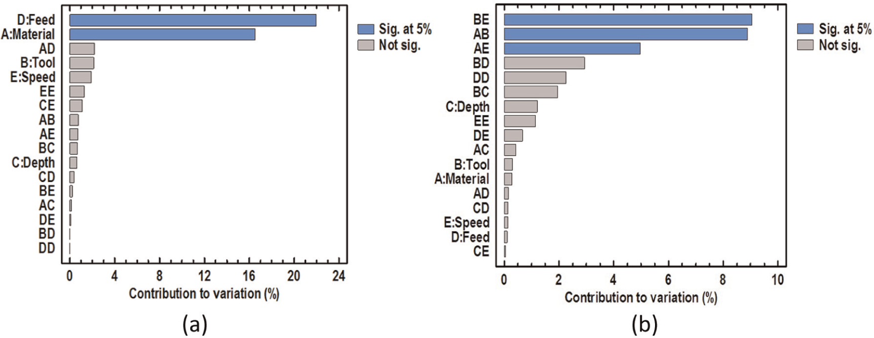
According to Figure 11(a), B5 height is dominated by direct effects of feed per tooth (D), material properties (A), depth of cut (C) and interaction effects between depth of cut and feed per tooth (CD), material properties and feed per tooth (AD) and cutting speeds (EE). The tool coating and insert nose radius (Rε) have negligible effects on B5 height.
Pareto chart of (a) B5 height and (b) B5 thickness.
As can be seen in Figure 11(b), direct effects of tool (B) and feed per tooth (D) are dominant parameters on variation of B5 thickness. Figure 11 clearly shows that cutting speed (E) has an insignificant influence on B5 size.
It is believed that during cutting operations with high engagements between cutting tool flutes and machined parts (e.g. milling), larger burr formation is anticipated. This is mainly caused by a change in the plastic zone size in the transition material ahead of the tool. In both milling and orthogonal cutting operations, tool exit creates forward flow of materials. Conversely, tool entrance induces the backward flow of material during orthogonal cutting. However, during milling of ductile materials such as AAs, tool entrance induces the forward flow of material. As a result, generated entrance burrs are not necessarily smaller than exit burrs. 9
As similar as exit burrs, in order to comfort deburring operation, entrance burrs minimization can be conducted by facilitating the transition of primary burrs to secondary burrs. In this case, entrance side burrs along up/down milling sides (B5 and B7) are formed instead of large entrance bottom burrs (B6). Increase in the depth of cut reduces the incidence of primary entrance bottom burr formation. Instead, longer and shorter entrance side burrs generated (see Figure 12). However, the maximum depth of cut is limited to stock material left during the roughing or semi-finishing process requirements and also minimum depth of cut demanded to suppress the chatter vibration.
Direct effect plot of (a) B5 height and (b) B5 thickness.
As can be seen in Figure 12, cutting tests on AA 2024-T351 (more ductile than AA 6601-T6) led to shorter and thinner B5 than those generated in AA 6061-T6. It is inferred that in ductile materials, larger primary entrance bottom burr (B6) and smaller entrance side burr (B7 and B5) are more likely to be formed. Furthermore, larger feed per tooth generates shorter and thicker B5.
Top burrs (B 4 and B 8 )
In milling operation, top burrs occur along up/down milling sides (B4 and B8). They are considered as Poisson burrs, formed by lateral deformation in the face of machined parts, which have a tendency to form through the longitudinal direction (see Figure 13).
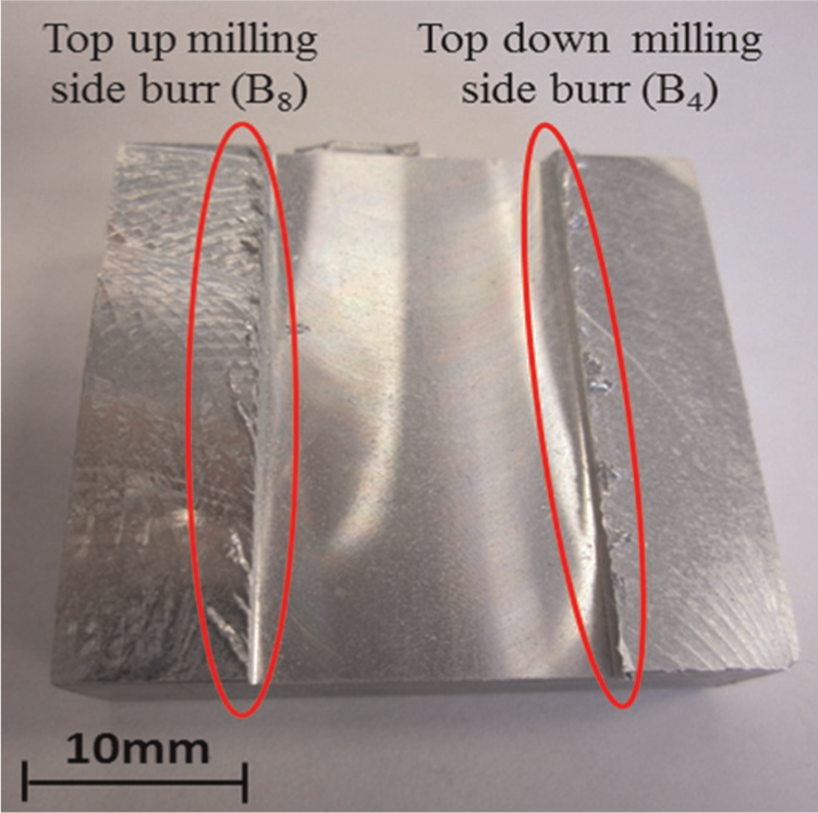
Slot milling top burrs.
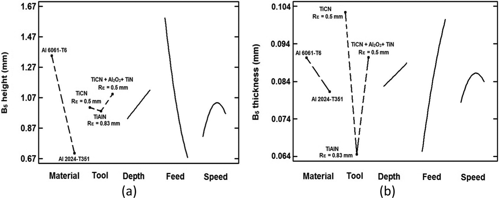
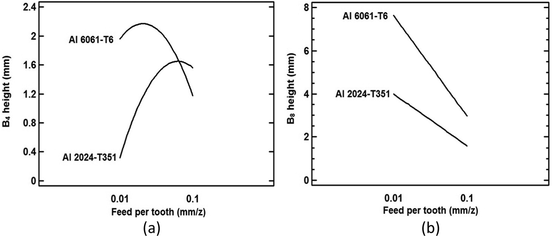
According to Figure 14(b), the most dominant parameters on B4 thickness are direct effects of feed per tooth (D), tool (B) and workpiece material (A). However, based on Figure 14(a), B4 height can be controlled by direct effects of tool (B), material properties (A), depth of cut (C) and interaction effects AD, AE, EE and DD. In addition, based on Figure 15, B8 height is mainly influenced by direct effects of feed per tooth (D) and material properties (A), while B8 thickness is influenced by interaction effects of tool–cutting speed (BE), material–tool (AB) and material–cutting speed (AE). It could be inferred that the dominant interaction effects on top burrs height are statistically insignificant parameters on top burrs thickness. In other words, top burrs thickness and height are dominated by different cutting parameters. In addition, the use of optimum setting levels of process parameters as shown in Figures 16 and 17 led to thicker top burrs in AA 2024-T351 and longer top burrs in AA 6061-T6.
Pareto chart of (a) B4 height and (b) B4 thickness.
Pareto chart of (a) B8 height and (b) B8 thickness.
Direct effect plot of (a) B4 height and (b) B4 thickness.
Direct effect plot of (a) B8 height and (b) B8 thickness.
The cutting tests with tool 2 (TiAlN, Rε = 0.83 mm) led to thinner and shorter B4 and shorter B8. According to Figures 16 and 17, changing the cutting tool 3 (TiCN + Al2O3+TiN, Rε = 0.5 mm) to cutting tool 1 (TiCN, Rε = 0.5 mm) generates shorter top burrs. This exhibits the significant influence of tool coating on top burrs, as similar as exit burrs (B1 and B2) and entrance down milling burr (B5).
When using high-speed machining, high temperature is generated on chip–tool contact area. As a result, small parts (fragments) of chip stick on machined surfaces and lateral machined face along down milling, when tool exits from the workpiece after each feeding motion. This results in thicker and longer top-down milling side burr (B4), as presented in Figure 16.
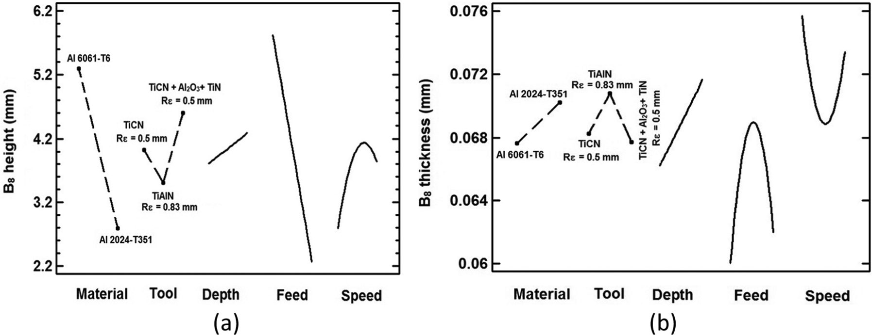
According to Figure 17(a), considerable B8 height was first occurred when using low level of feed per tooth. During slot milling operation, the chip is often unable to be evacuated. Therefore, it sticks on the top side (along up milling) of the corresponding lateral machined face and it eventually leads to longer top burrs along up milling side (B8), in particular when using higher levels of cutting speed and depth of cut and lower level of feed per tooth.
From Figure 18(a), it is evident that at lower feed per tooth, shorter B4 height is obtained for AA 2024-T351. When changing the feed per tooth to 0.1 mm/z, shorter B4 is obtained for AA 6061-T6.This exhibits that as presented in Figure 14(a), the interaction effects between material properties and feed per tooth (AD) have a significant effect on B4 height. Similarly, when lower level of feed per tooth is used, longer B8 is obtained in AA 6061-T6 (see Figure 18(a)). The difference between the B8 heights in both materials becomes smaller when changing the feed per tooth to upper level (0.1 mm/z).
Interaction effect of material-feed per tooth (AD) on (a) B4 height and (b) B8 height.
The B4 and B8 thickness are highly influenced by cutting speed and tool geometry and coating. As presented in Figure 19, at lower level of cutting speed, when using cutting tools with similar insert nose radius (Rε), lower resulting values of B4 and B8 thickness are obtained when using cutting tool 1 (TiCN, Rε = 0.5 mm). Vice versa, under similar cutting conditions, when cutting speed increases to 1200 m/min, thinner B4 and B8 are obtained when using cutting tool 3 (TiCN + Al2O3+ TiN, Rε = 0.5 mm). This exhibits significant interactions between cutting speed and tool coating that largely affects both B4 and B8 thickness.
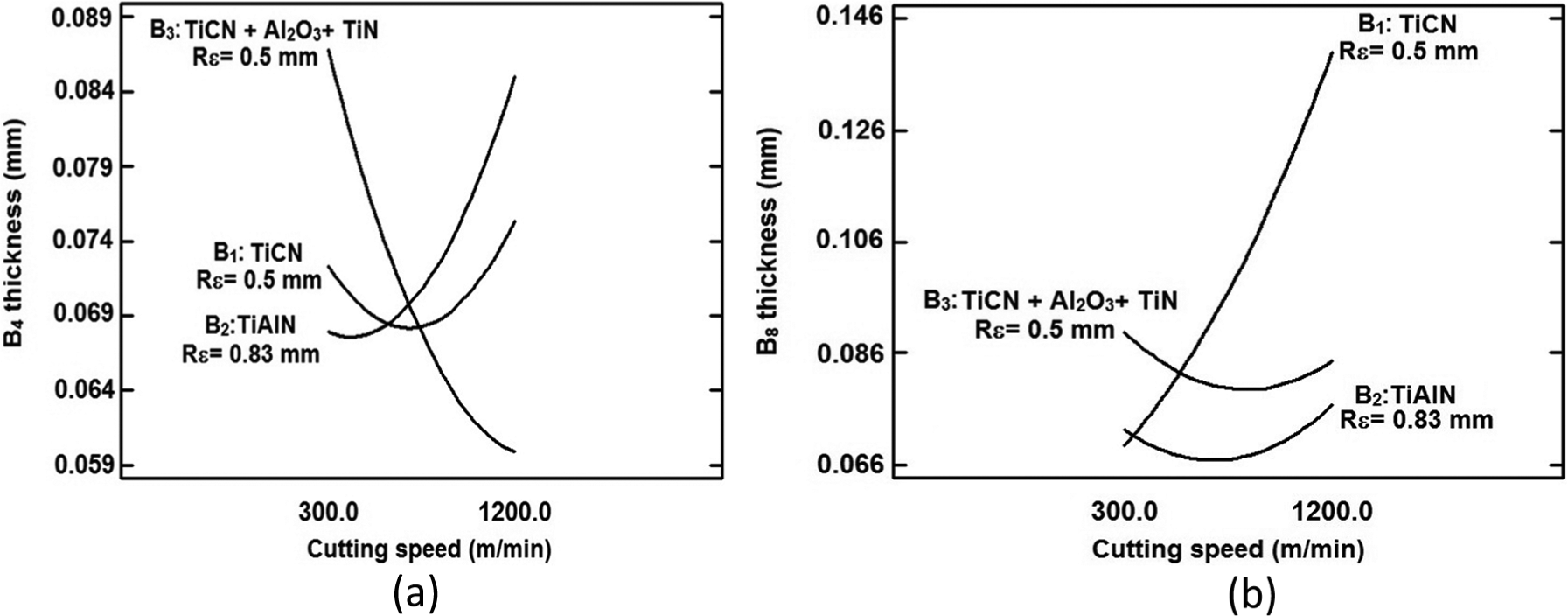
Interaction effect of tool-cutting speed (BE) on (a) B4 thickness and (b) B8 thickness.
Response surface models
Table 3 summarizes the factors and interactions that control each of the five burrs analyzed. The optimum cutting conditions to minimize slot milling burrs are also presented in Table 3. It appears that the optimum process parameters’ setting levels to minimize each burr are different (see Table 3). None of the two tested materials systematically have a higher size when a specific burr is considered.
Statistical summary of results.
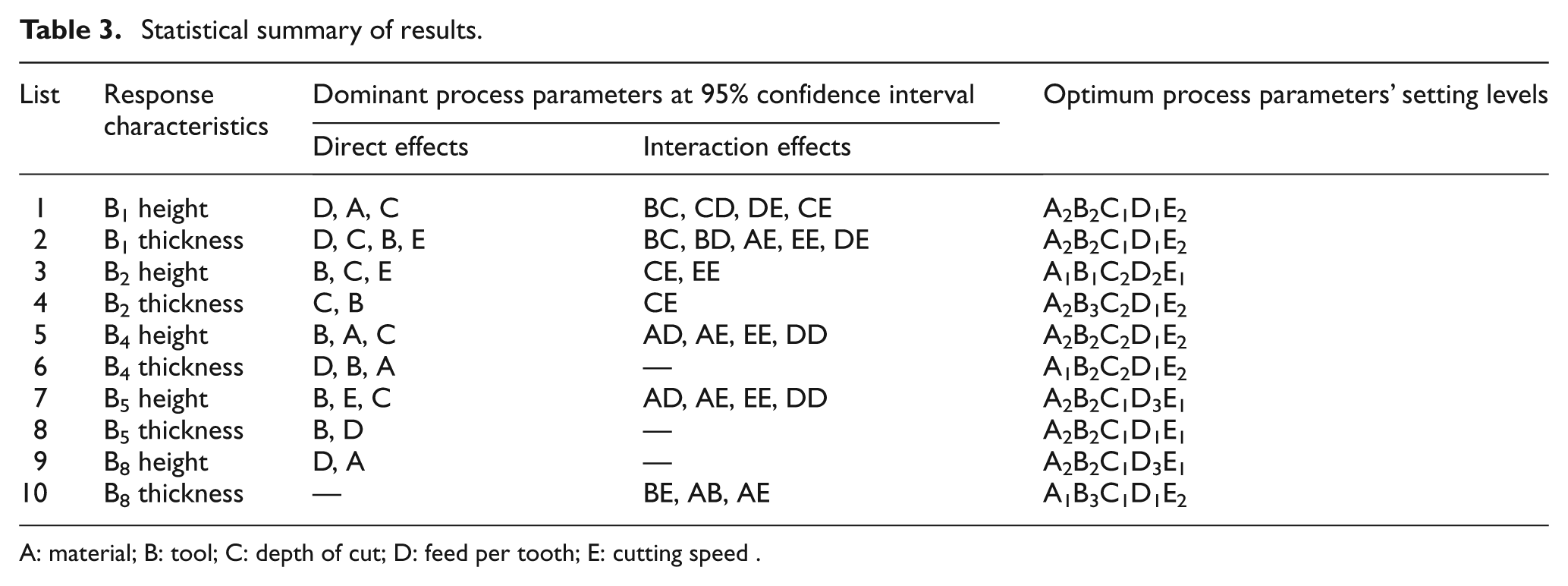
A: material; B: tool; C: depth of cut; D: feed per tooth; E: cutting speed
The three-dimensional (3D) response surface models of the optimum cutting condition are presented in Figures 20 and 21. According to Figures 20 and 21, the B1 is the longest and thickest burr among other burrs studied. From Figure 21, it appears that the heights of B2 and B5 are negligible as compared to other burrs studied.
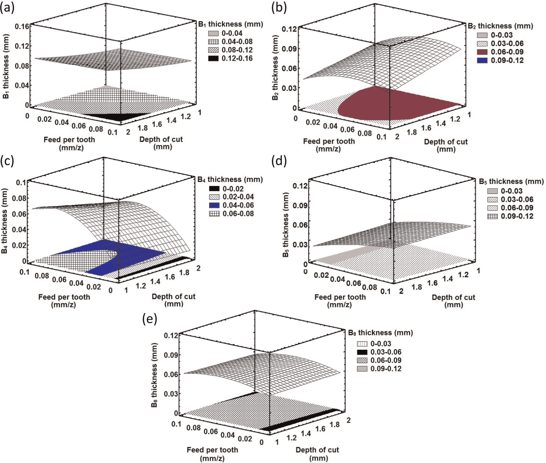
3D contour plot of burr thickness studied at optimum cutting conditions: (a) B1 thickness, (b) B2 thickness, (c) B4 thickness, (d) B5 thickness and (e) B8 thickness.
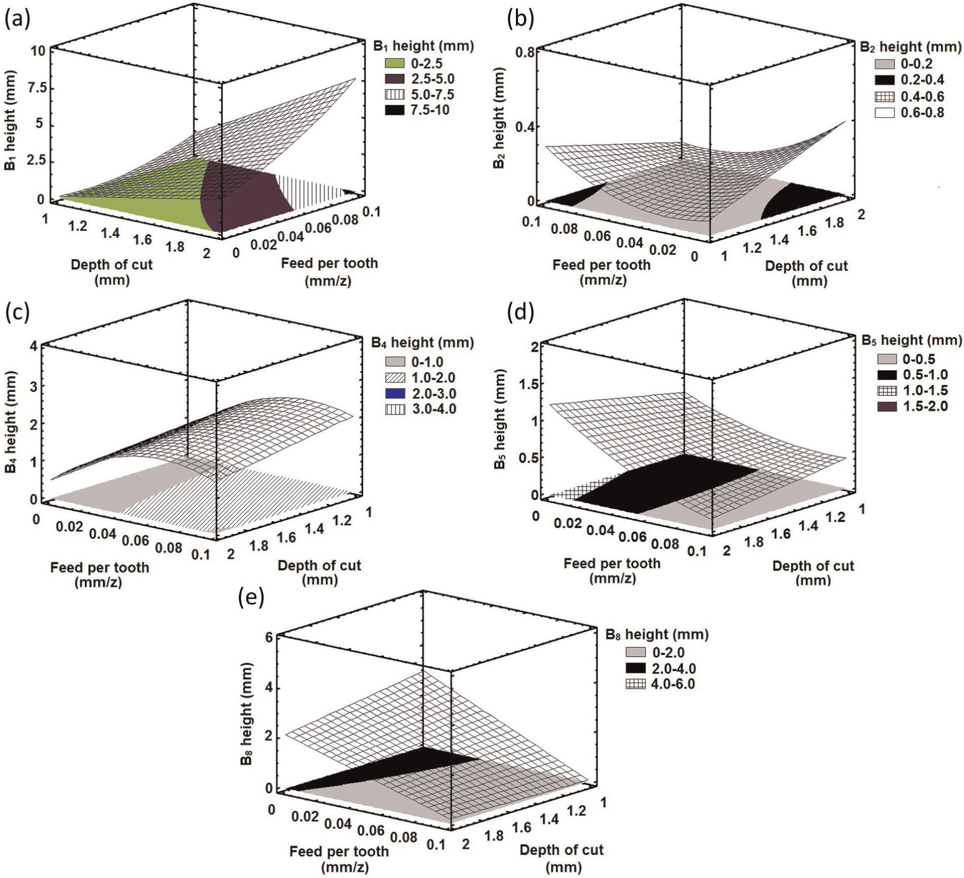
3D contour plot of burrs height at optimum cutting conditions: (a) B1 height, (b) B2 height, (c) B4 height, (d) B5 height and (e) B8 height.
According to Figures 20 and 21, in some of the burrs studied, no relationship can be formulated between the burrs and cutting parameters. This becomes more clear when studying the burr height. This can be due to interaction effects between process parameters, which may pose severe difficulties on burr formation modeling. Therefore, precise estimation of burr size becomes more difficult.
Conclusion
The slot milling burrs in AA6061-T6 and AA2024-T351 were comprehensively studied. Their formation mechanism and factors governing their creation were investigated using a multilevel factorial design of experiment. According to experimental results and statistical analysis, the following conclusions are drawn:
It was found that amongst most of the burrs studied, the dominant process parameters on burr height have the opposite effect on burr thickness. Moreover, no mathematical relationship was formulated between burrs thickness and height.
Depth of cut, feed per tooth and tool (insert nose radius and coating) were found as the most dominant process parameters on most of the burrs. The side burrs, whether entrance or exit side burrs (B1 and B5) are dominated by the feed per tooth. The top burrs are mainly affected by variation of cutting condition, chip evacuation dynamic, insert nose radius (Rε) and tool coating.
Burr size can be reduced significantly by selecting appropriate cutting parameters and cutting tools. However, optimum setting levels of process parameters to minimize each burr size are different. This can be known as a complex nature of milling burr formation. Considering that tool vibration was controlled, the variation of burr sizes is affected by other parameters, which their level of influence on milling burr size is not yet identified. This exhibits that optimizing the machining conditions to minimize the milling burrs is challenging.
The significant effect of coating on milling burrs was observed in this study. This observation is in contradiction with previous findings in the literature, stating minor influence of coating on face milling burr formation. In addition, high-speed machining has no significant effect on the top burr size. Furthermore, cutting tools with very similar insert nose radius (Rε) to depth of cut generate primary exit bottom (B2) burr, regardless of level of cutting speed used.
It was observed that milling burrs are highly influenced by interactive effects between process parameters. This may pose severe difficulties on precise modeling of burr formation and dimensions.
The results of this study can be useful for subsequent studies on modeling of burr formation mechanism in precision milling of AAs and other light metals to better find the optimum conditions and consequently adequate burr prediction and control.
Footnotes
Appendix 1
Acknowledgements
The authors would like to acknowledge the contribution of Mr Azziz Tiabi on collection of a part of experimental data presented in this work.
Funding
This work was supported by consortium for research and innovation in aerospace in Quebec (CRIAQ) and Fonds Québécois de la Recherche sur la Nature et les Technologies (FQRNT) by the intermediary of the Aluminum Research Centre—REGAL.
Declaration of conflicting interests
The authors declare that there is no conflict of interest.