
Abstract
This article presents an investigation into the wear of cutting tool during milling operation of Ti-6Al-4V using H13A carbide inserts. Wear tests were conducted using machining parameters (feed, speed, and depth of cut) falling in the permissible range recommended by the supplier of the inserts. A wear map was created to identify different regions that characterize the tool wear intensity. The wear map revealed a region of avoidance characterized by higher wear for cutting speed of around 55 m/min and feedrate of 0.15 mm/tooth. The Ti:Al ratio reached values between 4:1 and 6:1 for the cutting parameters that resulted in lower–tool wear rate. However, for higher wear rates, the ratio of Ti:Al did not exhibit any stability across the flank wear land. Scanning electron microscope and energy-dispersive x-ray analysis were performed on the worn inserts to identify the high–tool wear regions and material composition at different locations. Titanium aluminides (TiAl and TiAlN) were found just in the low–tool wear regions, and titanium nitride was found across the avoidance region in the wear map. Microscope and x-ray analysis of inserts in the safety zone clearly revealed a built-up edge on the cutting edge of the tools.
Introduction
The high strength-to-weight ratio, low density, and high corrosion resistance are well-known attributes of titanium alloys that are deemed useful for applications in aerospace. Moreover, titanium alloys are also being recognized in sectors such as refining of petroleum and chemical and food processing, marine applications, and automotive and biomedical industries (surgical implants). 1 Titanium-based alloys have low densities (∼4.5 g/cm3 higher than aluminum at 2.8 g/cm3 but considerably lower than steels ∼7.8 g/cm3) and exhibit excellent properties at high temperatures (Table 1). Titanium-based alloys also show good fatigue resistance that makes them suitable candidate materials for manufacturing load-bearing parts, especially in aerospace applications. 4
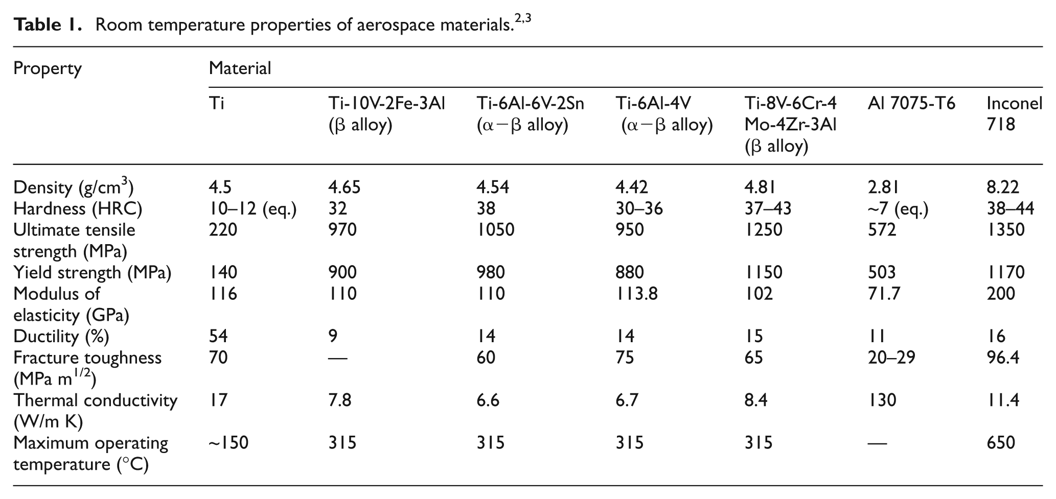
Commercially, pure titanium has higher corrosion resistance but shows inferior strength as compared with its alloys, as shown in Table 1. 5 Titanium alloys can be categorized as α-phase alloys, β-phase alloys, near-α alloys, and α–β alloys. α alloys are solution strengthened by adding small amounts of materials known as α-structure stabilizers such as aluminum, tin, zirconium, and palladium, whereas β titanium is because of β stabilizers that include molybdenum, vanadium, tantalum, niobium, manganese, iron, and chromium. Pure titanium usually occurs in all α phase. Ti-6Al-4V is a α–β alloy that is used in about 60% of all titanium products.6,7 Ti-6Al-4V is heat treatable and presents strength and stability at temperatures up to 400 °C, due to which it can replace many of the non-heat-treatable alloys. This alloy shows good metallurgical stability at temperatures in the range of 400 °C–483 °C6,8 while operating at higher temperatures could cause titanium fire. 4 Titanium alloys have poor machinability since they have a low thermal conductivity (k = 6.7 W/m K for Ti-6Al-4V; k = 50 W/m K for AISI 1045 steel) and a small heat-affected zone near the tool cutting edge. 1
Moreover, titanium alloys also conserve greater hardness level at elevated temperature as compared with conventional metals. 9 The cutting temperature typically encountered near the cutting zone at the tool tip was reported to be around 500 °C–600 °C, 10 which corresponds with a yield stress of around 500 MPa (Figure 1).
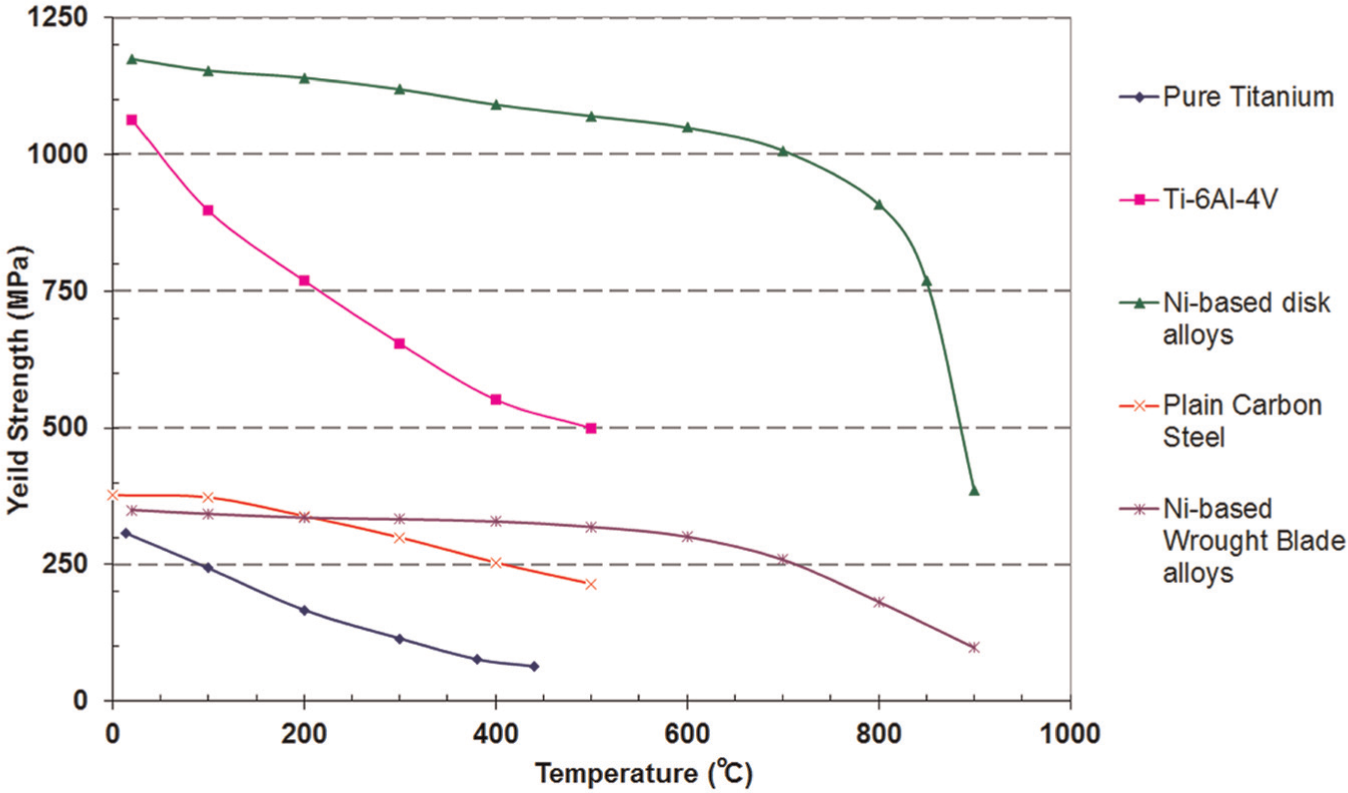
Cutting temperature and strength graph for different materials.
Komanduri and Reed 11 reported the difficulty of machining of titanium at cutting speeds higher than 30 and 60 m/min for high-speed steel and carbide tools, respectively. Being reactive, titanium chips tend to react with tool materials causing chemical dissolution. 12 Excessive chatter during machining results due to its low modulus of elasticity.13,14 It was also reported that the cutting temperatures of titanium alloys were 250 K higher than the cutting temperatures reported for carbon steel. The heat partition for titanium was reported to be 80% transferred to the tool while 20% was carried to the chips. 15 The mean tool–chip interface temperature as a function of the cutting speed for titanium, stainless steel, and AISI 1113 steel is presented in Figure 2. 16 As depicted in Figure 2, the higher temperature at the interface region means more heat being generated and transferred to the tool leading to greater tool degradation as compared with conventional materials.
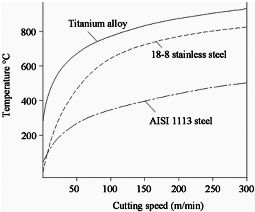
Cutting speed and cutting temperature graph for titanium alloy and steels.
Out of the total tools used in the industry, about 40% are coated tools, which performs 80% of the mechanical machining operations in the industry. 18 In order to machine titanium and titanium-based alloys, tool coatings are yet to be successfully implemented. 19 In titanium milling, chatter is also a critical limitation due to relatively high cutting force coefficients and limitations on surface speed. As a result, traditional techniques for stabilizing chatter cannot be easily applied. 20 Chatter was reported to be the main cause for significant increase in milling force and poor surface finish and high tool wear. 21 Table 2 summarizes the performance of coated tools during milling and drilling operations performed on titanium-based alloys; however, no satisfactory conclusion can be made for suitable coatings. Finite element simulations for the high-speed machining of titanium-based alloys predicted cutting temperature around 500 °C–600 °C resulting in tool wear. 10 It was also concluded that for machining titanium-based alloy ZTC4, the cutting temperature is primarily a function of cutting speed, cutting force a function of radial depth of cut (DoC) and cutting speed, and surface roughness a function of feedrate. Finite Element Method (FEM) results also predicted that the degree of chip segmentation and cutting forces increase with cutting speed for machining Ti-6Al-4V alloy. 33 For the case of milling steels, an investigation on AISI 1045 had revealed that increase in cutting temperature is strongly influenced by increase in cutting speed, followed by increase in radial DoC, with feedrate having least influence on cutting temperature. 34 However, considering the cutting forces, in the case of AISI P 20 steel, feedrate was reported to be the most dominant factor followed by axial DoC and cutting speed. 35 The surface roughness in the case for milling 190 Brinell Hardness Number (BHN) steel was reported to have been strongly influenced by feedrate while the effects of axial DoC and cutting speed were found to have negligible effect. 36 Owing to its poor machinability, researchers are also actively investigating alternate processes such as abrasive water jet (AWJ) cutting for processing of titanium alloys.37,38
Performance of various tool materials during intermittent cutting. 16
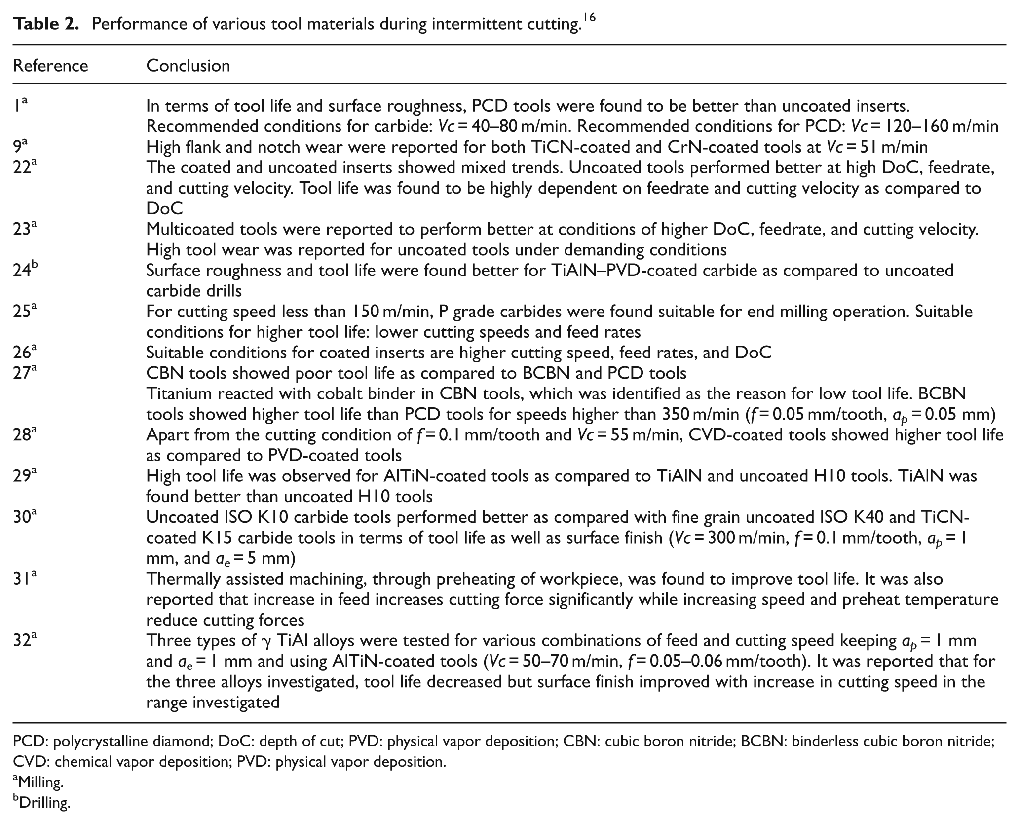
PCD: polycrystalline diamond; DoC: depth of cut; PVD: physical vapor deposition; CBN: cubic boron nitride; BCBN: binderless cubic boron nitride; CVD: chemical vapor deposition; PVD: physical vapor deposition.
Milling.
Drilling.
The metal removal rate (MRR), cycle time, tool wear, and machine downtime influence machining efficiency. 39 In this context, selecting the most optimal machining conditions and parameters can be crucial when machining difficult to cut materials. Identification of the range suitable conditions (such as feeds and cutting speeds), which provides the best tool life, is thus important. For this purpose, wear maps can prove to be useful tools toward achieving this goal. Wear maps have previously been presented for turning ferrous alloys40–45 and Ti-6Al-4V alloy. 4 Since, most Ti-6Al-4V monolithic components are manufactured by end milling using solid mill cutters in aerospace industry, 46 there is a strong case to explore the development of the wear map approach for milling operation for titanium-based alloys. It is also important that the suitable tool, geometry, coating, and cutting flow materials be used for precision components. 9 The high tool wear is known to increase the surface roughness of the parts and thus reducing quality of the manufactured parts. 47
The process of milling is one of the most common machining operations in the industry. In the process of milling, the main power rotates a cutting tool (rather than the workpiece, as in the case of turning), with the prismatic workpiece undergoing feed motions. 48 Moreover, as compared with turning, the cutting tool used in the milling operation may have several cutting edges, or flutes, with each edge cutting intermittently.
Milling can further be classified into face milling and end milling. In a face milling operation, the milling cutter cuts the workpiece with its face, thereby creating a flat surface. During the end milling operation, the cutter face along with the edges of the milling cutter is engaged with the workpiece. End milling may either be up milling or down milling. In the former case, the feed motion is opposite to the peripheral movement of the tool. In down milling, feed motion is in the same direction as the peripheral movement of the tool. 49 In down milling, however, there is a tendency for the chip to become wedged between the insert causing tool breakage. 50 Low tool wear has been reported for down milling as compared with up milling operations.51,52
The objective of this research is to present a tool wear map constructed to study the dry milling of Ti-6Al-4V alloy using uncoated carbide tools (H13A carbide inserts). This wear map constitutes a basic instrument to identify regions characterized by different tool wear intensities and specific wear mechanisms associated with the tool deterioration. The constructed wear map was used to study the wear mechanisms in critical (selected) areas of interest. In this way, a better understanding was developed for the tool–workpiece interface tribology during the machining process. This knowledge ultimately would lead to the designing of new tools or processes to improve the machinability of titanium-based alloys.
Milling and tool wear evaluation
Since milling is an intermittent cutting process, instead of being constantly engaged with the workpiece during machining, the tool engages and disengages periodically as the tool is fed into the workpiece. As a result, while empirical formulae associated the wear rate parameter R to yield the results as in the case for turning, practically, the active length of engagement of the tool with the workpiece must be considered. The wear rate parameter for turning has previously been defined 16 according to the following equation

where VB is the tool flank wear and t is the time of active tool engagement.
The wear rate parameter R, as evident from equation (1), is calculated by taking logarithm of the ratio of flank wear and linear length of cut. As linear length of cut will always be greater than flank wear, the value of R will be negative in all viable machining conditions. Hence, a higher numerically magnitude with a negative sign depicts a lower flank wear and therefore higher tool life. However, milling is a more complicated and intermittent material removal process where the chip load varies with time. These factors contribute to rapid mechanical as well as thermal loading at the cutting region of the tool. As a result, mechanical and thermal fatigues also come into play in addition to the tool wear processes involved in turning. Preliminary tests were conducted during this research to normalize flank wear in terms of the material removal rate, chip load, and the actual contact length between the tool and the workpiece. It was found that all the machining parameters, namely, feedrate, cutting velocity, and axial and radial DoCs, have their contributions toward tool life. 16 Moreover, even the type of milling process (up or down milling) affects tool life.51,52 DoC has very little effect on tool life as compared to the feedrate and cutting speed. 22 Therefore, the suitable wear rate parameter for the case of milling that was used here to normalize flank wear, can be expressed in terms of the tool/workpiece contact distance, takes the following form

where l is the linear length of cut.
Experimental details
Unified experiments were conducted in the course of the present research on Ti-6Al-4V alloy. Figure 3(a) shows microstructure of the titanium alloy used for this research. The microstructure before machining shows a typical α–β structure found in Ti-6Al-4V alloy. Figure 3(b) shows the indentation marks for nanohardness testing. The average value of nanohardness tests performed on this material revealed hardness of 3.824 GPa with a standard deviation of 0.384.
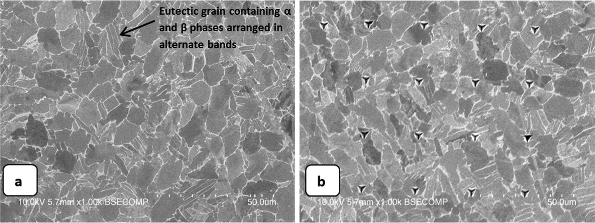
(a) Microstructure of Ti-6Al-4V alloy and (b) indentation marks from nanohardness test on Ti-6Al-4V alloy.
Vertical end milling tests were conducted using Sandvik® TPMN 160308-H13A carbide inserts. Since the milling process involves rapid loading and unloading of the tool–workpiece interface, the signature of tool–workpiece interactions, which was so well preserved in the case of turning, would likely be reduced considerably. During these experiments, work material was selected from the same material stock as recommended in the ISO 8688-2:1989 (E). 49 Each cutting pass was made using a fresh insert. Moreover, each pass represented specific cutting parameters, that is, feed/tooth, cutting speed, and axial and radial DoCs. A fresh insert was mounted on the tool holder for each cutting pass. The axial DoC ap was maintained constant at 1 mm, and the radial DoC ae was 4 mm. Only one insert was used during each pass to avoid discrepancies associated with radial runout. The effective tool diameter for this tool configuration was 32 mm. In order to exaggerate the effect of milling parameters on tool wear, all experiments in this research for the purpose of wear map construction were conducted in dry condition and up milling configuration.
Results and discussion
The data extracted from unified milling experiments were used to prepare a wear map for H13A inserts, as shown in Figure 4. The map shows different regions that describe the intensity of flank wear experienced by the tool as also observed by other researchers.40,41 As in the case of turning, this wear map also revealed a region of avoidance indicated as “region of avoidance” where the tool experiences a higher degree of wear as compared with surrounding regions (minimal tool wear region). Otherwise, higher tool wear is found in areas corresponding with more challenging cutting conditions, that is, very low or very high feeds and cutting speeds combination. This region was investigated in detail along with outlying areas of low tool wear surrounding it. The methodology (using energy-dispersive x-ray (EDX) analysis) used to analyze wear mechanisms had previously been devised to study a similar phenomenon encountered in turning of the same material. The EDX analysis is presented later in the “Results and discussion” section. The trend seen herein is in agreement with the previous research reported for turning. It may also be mentioned here that the wear map is basically a contour map widely used by researchers in tribology as well as machining to analyze wear rate, wear mechanisms, surface integrity, burrs, and so on. The different regions of wear rates as indicated in Figure 4 were selected using the high–, moderate–, and low–wear rate parameter magnitudes as reported in a previous research. 53 As a wear map is basically a contour graph depicting convenient divisions in wear rate, a crisp definition of these boundaries remains an area to be debated. However, as per EDX analysis, within each band/zone, similar wear mechanisms prevail.
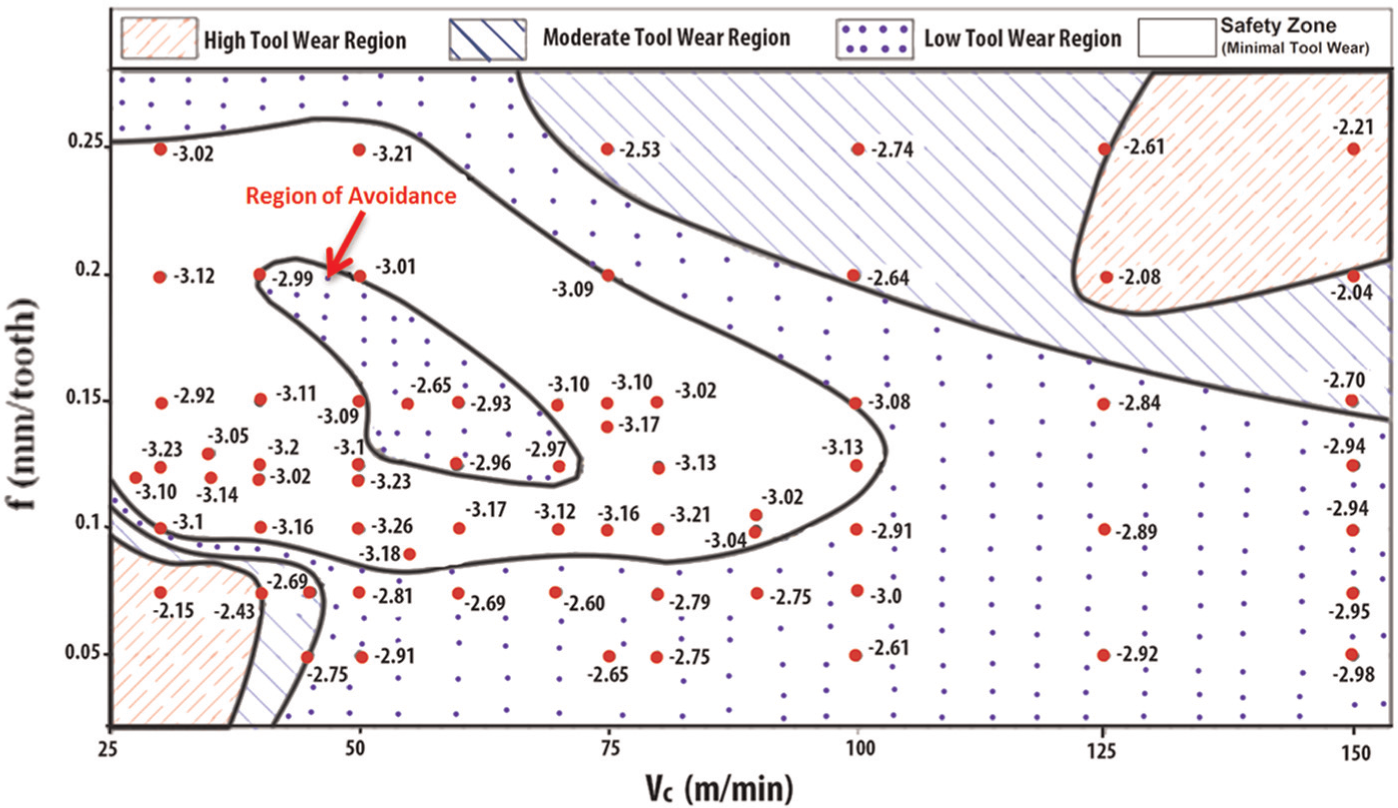
Tool wear map for milling of titanium alloy (Ti-6Al-4V) using uncoated H13A tools (axial depth of cut, ap = 1 mm and radial depth of cut/step-over, ae = 4 mm).
Greater chip formation at the cutting edge was observed in the case of milling as compared to turning due to rapid loading and unloading cycles. As pointed out by an earlier research, when indentation tests were carried out at high temperature on different cubic boron nitride (CBN), coated carbide, and polycrystalline diamond (PCD) tools, rupture always occurred in the tool material, leading to extensive chipping of the tool material that is also observed here. 54
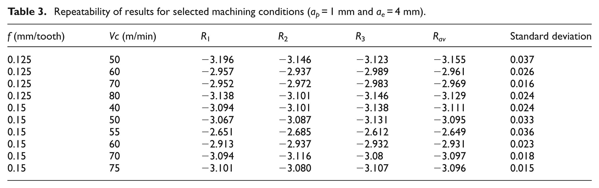
In order to ensure repeatability of wear rate values, tests were repeated for test conditions in areas of interest (region of transition marked in the wear map as the region of avoidance). Due to the high cost associated with titanium-based alloys, only these selected cutting conditions were tested for repeatability while the regions following a normal trend were not tested for repeatability. A summary of results for these follow-up tests is presented in Table 3. From Table 3, it is clear that the repeat values show a high degree of repeatability.
Repeatability of results for selected machining conditions (ap = 1 mm and ae = 4 mm).
The region of avoidance in the midst of the safety region in Figure 3 corresponds approximately with similar machining conditions in terms of feed and cutting speed as in the case of turning. A closer examination of the tools used across the region of avoidance in this wear map under scanning electron microscope (SEM) and EDX indicates the high wear in the tools.
Figure 5 shows the position of an EDX line scan across the high-wear flank face. Data from the line scans across the avoidance region in the wear map show the presence of titanium nitride and titanium aluminides (Ti x Al and TiAlN). Among the alloying elements present in Ti-6Al-4V, titanium showed greatest tendency to adhere to the tool, followed by aluminum. Vanadium showed least tendency to transfer onto the inserts. It was therefore assumed that the presence of vanadium on the tool was part of the transfer of the workpiece alloy. The mass percentage of vanadium was therefore used to calculate the amounts of titanium and aluminum present in the flank wear region in the form of alloys. The masses of titanium and aluminum that took part in reactions in the cutting region were therefore estimated. Since this process is not taking place in a controlled fashion, pockets might occur where the alloy was not being deposited, especially away from the cutting edge. As a result, calculations based on the aforementioned assumption would yield negative values for the ratios. The presence of titanium nitride and titanium aluminides as per the aforementioned methodology can therefore be gaged from the stability in the ratios of Ti:Al and Ti:N in a similar manner as was in the case for the wear map for turning. 16
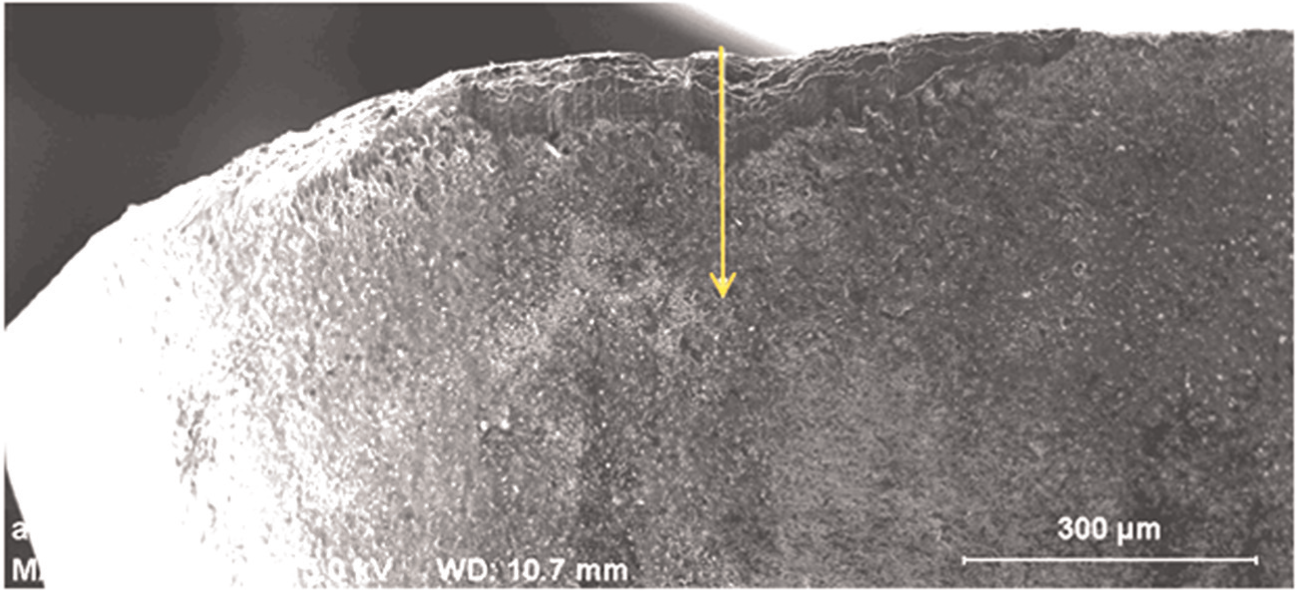
EDX line scan for flank wear land (magnification: 100×; f = 0.15 mm/tooth, Vc = 55 mm/min).
As shown in Figure 6, the occurrence of both Ti x Al and TiAlN is probable in the low–tool wear regions while TiN is expected to be formed in higher tool wear regions (Vc = 55 m/min and f = 0.15 mm/tooth). The ratio of Ti:Al showed a stable trend around 4:1–6:1 in low–wear rate regions. The ratio of Ti:Al does not show such stability for higher flank wear. The ratio of Ti:N remained stable, 0.5:1–1.5:1 for all cutting conditions considered, which is found to be consistent with its compositional variation (TiN0.6–TiN1.1). 55 The experimental results indicate that for regions where no stability occurred in the Ti:Al ratio, titanium had been reacting with nitrogen to form nitrides. However, since the thermal conductivity of titanium nitride is substantially higher as compared with titanium aluminides, higher tool wear resulted. Microscope and x-ray analysis of worn inserts in the safety zone show a built-up edge (BUE) on the cutting edge of the tools. Similar results were also reported for turning of titanium alloy (Ti-6Al-4V). 16
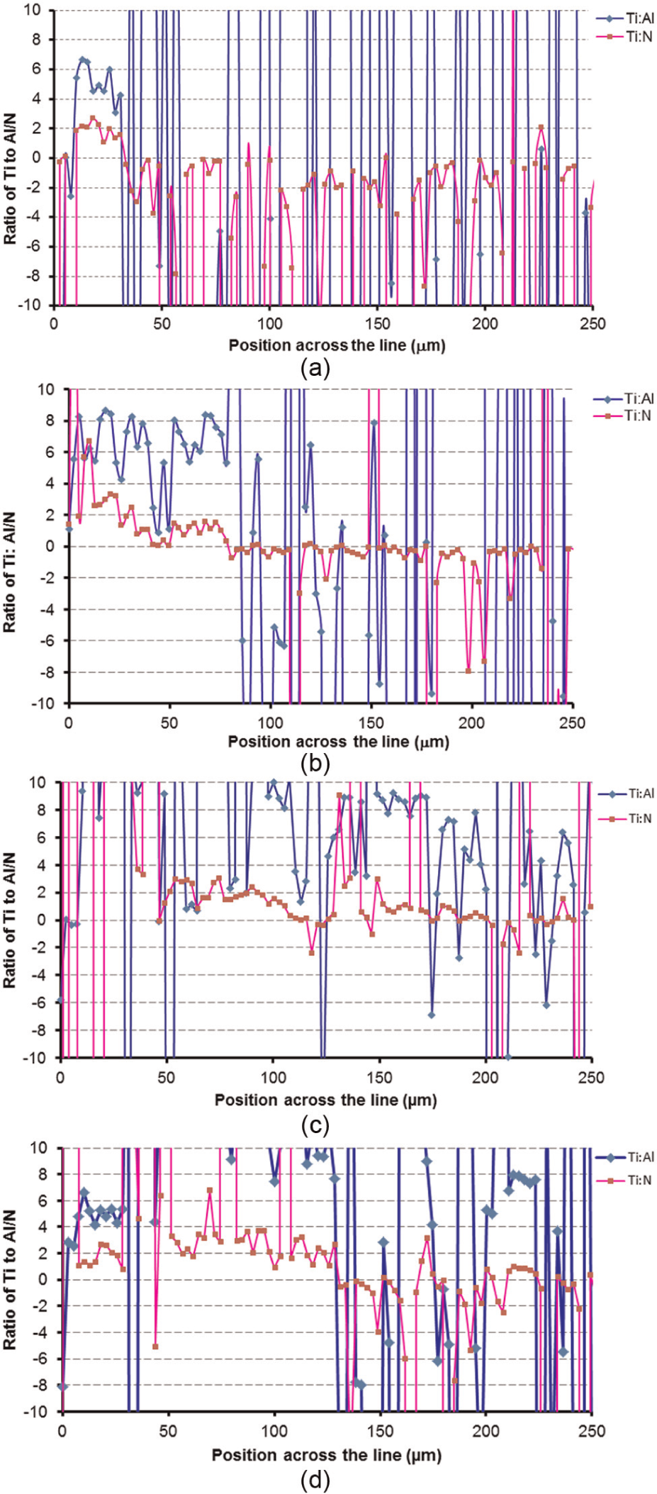
(a) f = 0.15 mm/tooth, Vc = 40 m/min; (b) f = 0.15 mm/tooth, Vc = 50 m/min; (c) f = 0.15 mm/tooth, Vc = 55 m/min; and (d) f = 0.15 mm/tooth, Vc = 70 m/min.
The EDX analysis presented herein supports the use of AlTiN-based coatings on carbide tools for machining titanium-based alloys. This conclusion is supported by results from previous researchers who have investigated the machinability of titanium alloys using coated tools wherein such coatings tend to perform better than uncoated and conventional coated tools (TiN, TiC, and TiCN coatings).24,29,56
Conclusion
Since titanium-based alloys are categorized as difficult to machine materials, wear maps for milling these materials would prove useful toward optimization of this process. The wear map presented herein for up milling of Ti-6Al-4V alloy using uncoated carbide tools (H13A grade straight carbide) shows regions that can be classified as high-medium–tool wear and low–tool wear zones. As in the case of a previous investigation 4 using similar tools for turning of the same alloy, there is a region of high tool wear in the midst of low–tool wear region (described as a region of avoidance). This region was observed in the vicinity corresponding with a feedrate of 0.15 mm/tooth and a cutting speed of 55 m/min. For higher tool life and greater productivity, this region should be avoided. There is evidence of the formation of titanium nitride (Ti x Al and TiAlN) and titanium aluminides. TiAlN is observed for lower flank wear while TiN is observed for higher flank wear. BUE was also observed on the cutting edge of the tools in the safety zone.
This research presents a strong case toward the development of AlTiN-based coated carbide tools and their experimental validation in order to improve the machinability of titanium-based alloys. Further research to this effect is recommended and envisaged to achieve this purpose.
Footnotes
Appendix 1
Funding
This research received no specific grant from any funding agency in the public, commercial, or not-for-profit sectors.