
Abstract
Machining processes are inherently involved with tool wear, which is an influential factor in cutting forces, surface roughness, and machining costs. In conventional machining of some materials, there are some limitations regarding rapid wear of tool and large machining forces. As a result, new machining techniques have been developed in recent years, among which is the ultrasonic-assisted machining. This machining method is a combination of ultrasonic vibrations with conventional machining process. The goal of this article is to compare the tool life in ultrasonic-assisted milling and conventional milling processes. In experimental tests, one-dimensional ultrasonic vibrations have been applied on workpiece in the feed direction of tool. By varying spindle speed, the width of flank wear land of cutting tool has been obtained in ultrasonic-assisted milling and conventional milling processes, and the results are compared with each other. Due to tool rotation, the direction of workpiece vibrations with respect to edge of cutting tool varies in time. Consequently, there is the possibility of improper and uncontrolled contacts between tool and workpiece. In order to examine this issue, the relative speed of workpiece in normal direction of tool flank surface has been obtained analytically, and the results have been used in explaining the experimental observations. The experimental results have shown that in spindle speeds of n = 500, 1000, and 2000 r/min, tool life in ultrasonic-assisted milling process is less than in conventional milling process; however, for spindle speed of n = 3150 r/min, due to change in tool wear mechanism and decrease of relative speed of workpiece in normal direction of tool flank surface, tool life in ultrasonic-assisted milling process becomes larger than that in conventional milling process.
Introduction
The conventional machining of some materials such as austenitic steels, nickel- and cobalt-based superalloys, and titanium alloys rises to built-up edge, large cutting forces, high tool temperature, and consequently rapid and severe wear of cutting tool. One technique to overcome these problems is known as ultrasonic-assisted machining. In this machining process, high frequency (20–60 kHz) and low amplitude vibrations (1–40 µm) are added to conventional machining processes. Some advantages of this technique include lower machining forces,1–3 better penetration of lubricant into cutting zone, 4 lower cutting temperature,4,5 higher tool life, 6 higher machining accuracy,7–9 improvement of surface quality,8–13 burrs of lower height,14,15 and better chip formation.8,9,11,16
Ultrasonic-assisted turning has been investigated extensively. Jin and Murakawa 7 considered the chipping of the tool edge during the one-dimensional (1D) ultrasonic vibration turning caused by the colliding or rubbing between the flank of cutting tool and the surface of the workpiece when the tool was moving backward. They showed that flank wear width was much larger than that in conventional turning process. Nath and Rahman 11 investigated 1D ultrasonic-assisted turning of Inconel 718 with CBN tool. They concluded that at cutting speeds lower than 10 m/min, tool wear in ultrasonic-assisted turning is negligible, but at higher cutting speeds such as 15 and 20 m/min, due to increase in tool–workpiece contact ratio, tool tip and cutting edge wear drastically. Nath et al. 12 showed that the cutting force and tool flank wear of PCD tools while turning sintered tungsten carbide with the ultrasonic elliptical vibration turning method decrease significantly if the ratio of the nominal cutting speed to the maximum tool vibration speed in the cutting direction was small.
Azarhoushang and Akbari 8 investigated ultrasonic-assisted drilling of Inconel 738-LC. In contrast to ultrasonic tests, all conventional drilling tests were unsuccessful, and all drills broke at exit. Hsu et al. 5 investigated the machining characteristics of MAR-M247 using ultrasonic and high temperature–aided cutting. Experimental results demonstrated that slow cutting speed resulted in less flank wear, and an increase in vibration frequency increases flank wear. Furthermore, ultrasonic vibration has been used in modern machining methods. Shervani-Tabar and Shabgard 17 showed that increases in the amplitude and frequency of the tool vibration increase the rate of metal removal from the workpiece in ultrasonic-assisted electrical discharge machining.
Tool life is normally defined by the machining time for given flank wear land width. In this article, flank wear has been measured in accordance with the ISO 8688-2 standard for tool life testing of end milling. 18
The goal of this study is to compare tool life in ultrasonic-assisted milling (UAM) and conventional milling (CM) processes. For experimental purposes, one-dimensional ultrasonic vibration has been applied to workpiece in the tool feed direction. By varying spindle speed in both processes, wear width at tool flank surface has been obtained with respect to machining time. The temporal history of tool wear has been used for finding tool life.
For describing experimental observations, analytical relations of relative speed of workpiece in the normal direction of tool flank surface have been used. In spindle speeds of n = 500, 1000, 2000 r/min, tool life in CM is larger than that in UAM; however, in n = 3150 r/min, tool life in UAM is considerably larger than that in CM.
Analytical relations
Impact force between two bodies is proportional to second power of impact velocity of two bodies. In UAM process, due to workpiece vibrations, impact forces change wear mechanism in comparison with CM process.
For further investigating UAM process and in order to show the contact behavior between the newly machined surface of workpiece and tool flank surface, the relative speed of workpiece in the normal direction to tool flank surface has been calculated.
Figure 1 shows schematically the contact between tool and workpiece in the UAM process. In this process, tool tip performs a rotational motion around tool axis (with speed of v) and a feeding motion (with speed of vf) along x-axis and workpiece vibrates along tool feed direction with a speed of vv.
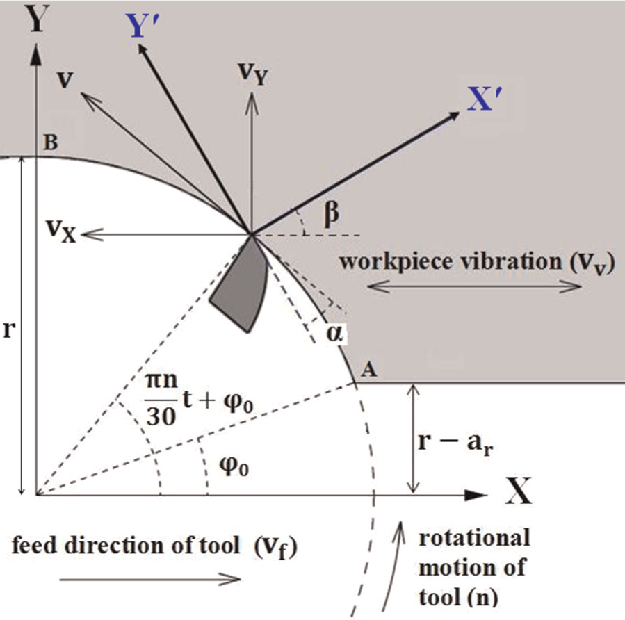
Tool–workpiece engagement geometry in the UAM process.
Regarding its circular motion, the position of tool tip becomes as follows


where r is tool radius, ωtool is tool angular frequency, and ϕ0 is initial engagement phase of tool–workpiece.
Angular frequency and initial engagement phase of tool–workpiece are determined from the following relations

where n is spindle speed, ar is radial depth of cut, and ftool is frequency of tool rotational motion.
By taking the time derivative of equations (1) and (2), cutting speed in X and Y directions is obtained


Assuming that vibration displacement of workpiece to be xw= asin(2πft), then vibration velocity of workpiece becomes

where f and a are vibration frequency and amplitude, respectively.
At any moment, the rotation of X′Y′ coordinate system, coinciding on tool flank surface and normal to it, with respect to XY, is equal to β. According to Figure 1, angle β is determined in the following form

where α is tool clearance angle. Finally, the relative speed of workpiece in direction normal to tool flank surface is calculated as follows

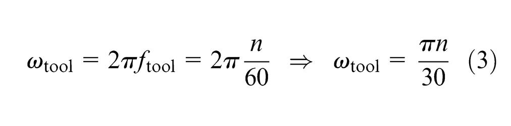
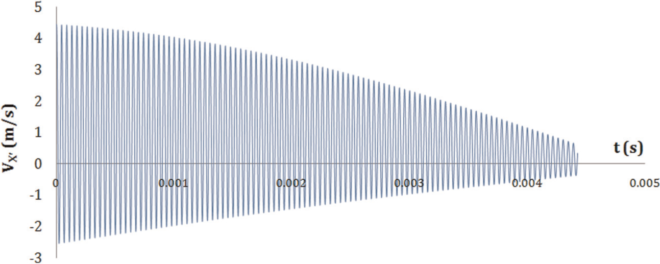
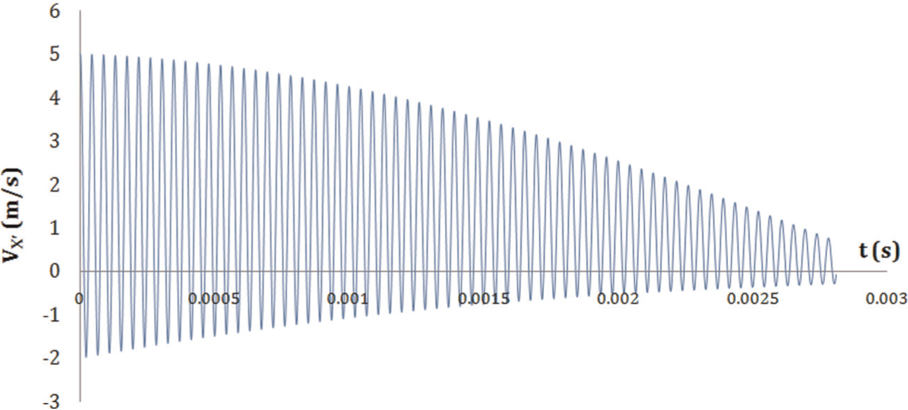
In the above relation, vf is tool feed speed. Figures 2–5 show the relative speed between workpiece and tool in the normal direction to tool flank surface and in one-stage engagement of tool and workpiece (from points A to B in Figure 1) for spindle speeds of n = 500, 1000, 2000, and 3150 r/min, respectively. Constant parameters in these figures include the following: feed per tooth fz = 0.1 mm/tooth, radial depth of cut ar = 2 mm, vibration frequency f = 23 kHz, and vibration amplitude a = 28 µm. Negative speeds indicate contact between newly machined surface of workpiece and tool flank surface.
Relative speed of workpiece and tool in the normal direction to tool flank surface for n = 500 r/min.
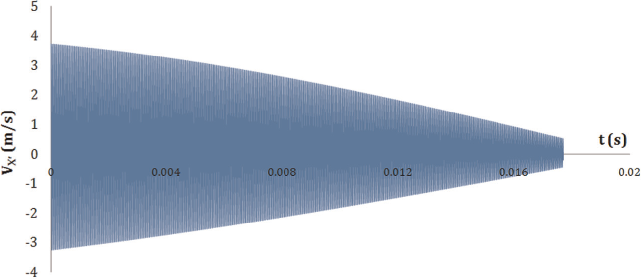
Relative speed of workpiece and tool in the normal direction to tool flank surface for n = 1000 r/min.
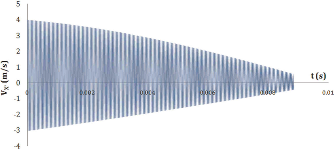
Relative speed of workpiece and tool in the normal direction to tool flank surface for n = 2000 r/min.
Relative speed of workpiece and tool in the normal direction to tool flank surface for n = 3150 r/min.
As shown in Figures 2–5, as tool rotational speed increases, relative speed of workpiece normal to tool flank surface and in direction to impact it reduces, and negative speeds tend to positive values. Therefore, as spindle speed increases, workpiece impacts on tool flank surface decrease.
Experimental setup
For milling operations, a 2.5-axis Deckel milling machine has been used. A 9255B model Kistler dynamometer has been also installed on milling table for measuring cutting forces. In order to properly conduct experiments with ultrasonic vibrations, workpiece has been connected to an intermediate part at the location of vibration node with two bolts and pins. Workpiece dimensions (43W × 57H × 100L mm) have been determined by finite element analysis, such that during the tests, a longitudinal standing wave was created along the workpiece length with two loops at the ends and a vibration node at its middle. Finally, intermediate part has been clamped. A 3-kW piezoelectric transducer has been used for generating ultrasonic vibrations. For converting city power to the required voltage and frequency for transducer, an MPI-made 2-kW ultrasonic power supply has been used. Transducer has been attached to one end of workpiece using an acoustic Mylar washer and one grub screw.
For measuring maximum vibration amplitude, a PU-09 gap sensor (0.4 mm/V), an AEC-5509 converter, and an oscilloscope have been used. This sensor has been located in a distance of 0.2 mm normal to the center of end face of the workpiece, and output in voltage can be monitored on oscilloscope. By moving from end to midsection of workpiece, the amount of vibration amplitude changes from 28 to 0 µm, and moving from midsection toward the other end face attached to the transducer, the amplitude increases from 0 to 28 µm. A AM-413T Dino-Lite digital microscope has also been used for measuring flank wear width. Figure 6 shows experimental setup.
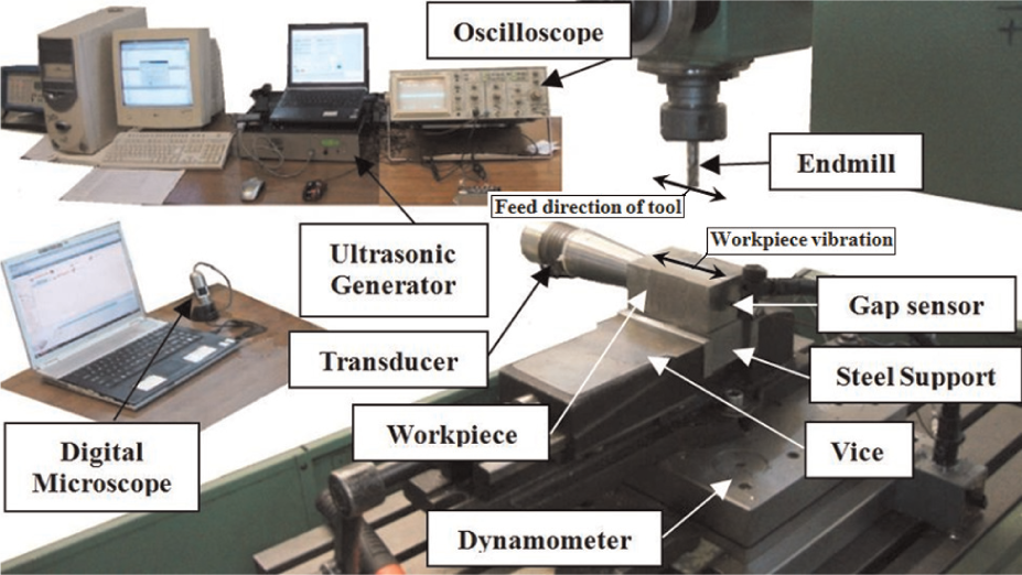
Experimental setup.
Workpiece material is AISI 304 austenitic stainless steel. The 1D vibrations have been applied in the feed direction of tool on workpiece. In each experimental test, a new 4-flute end mill of D = 10 mm diameter and 7° clearance angle from HSS has been used.
Tests have been conducted in both UAM and CM forms with spindle speeds of n = 500, 1000, 2000, and 3150 r/min, axial depth of cut aa = 4 mm, radial depth of cut ar = 2 mm, and feed per tooth of fz = 0.1 mm/tooth. In vibration-assisted machining, critical cutting speed (vcr) is defined as the speed lower than that tool–workpiece separation occurs in a portion of vibration cycle. Spindle speeds have been selected such that tool–workpiece separation takes place. Ultrasonic tests were performed at frequency of f = 23 kHz and amplitude of a = 28 µm.
Experimental results and discussion
The damages of a cutting tool are influenced by the stress and temperature at the tool surface. 19 Adding ultrasonic vibrations to machining process and consequently periodic separations of tool and workpiece change chip removal and subsequently wear mechanisms. In ultrasonic milling in which vibrations are applied to workpiece, during a single tool rotation, the relative position of tool cutting edge and direction of applied vibrations change. Moreover, applying ultrasonic vibrations to workpiece result in thermal softening and acoustic softening in workpiece. 20 Therefore, investigating tool life in ultrasonic milling process and comparing the results with those from CM and explaining the observed differences are a difficult task.
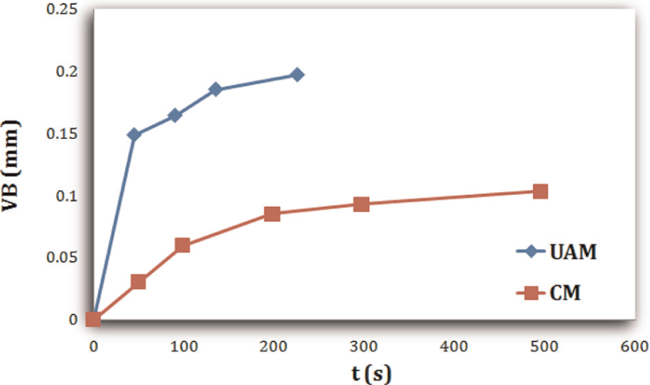
In experimental tests, width of the flank wear land has been measured. Figure 7 shows the temporal history of width of the flank wear land at spindle speed of 500 r/min. Constant parameters in Figures 7–13 are similar to those in Figures 2–5. As shown in Figure 7, the amount of tool wear in UAM is larger than that in CM process for n = 500 r/min. Figure 8 shows tool flank surface after 300 s machining with n = 500 r/min in both CM and UAM processes. It is clear that tool flank surface in UAM process wears uniformly, but in CM process, it is covered by workpiece materials and results in less wear.
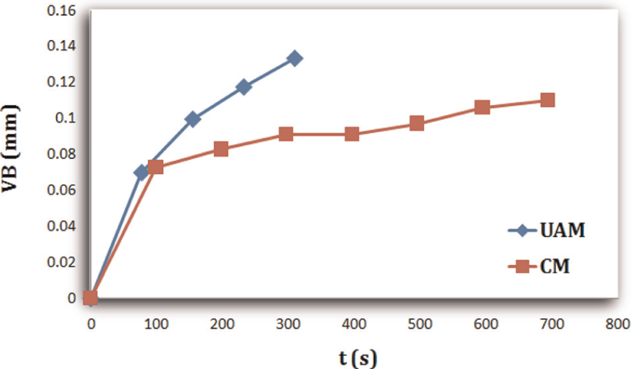
Time history of flank wear land width at n = 500 r/min in CM and UAM processes.
Tool flank surface after 300 s of machining at n = 500 r/min in CM and UAM processes.
Time history of flank wear land width at n = 1000 r/min in CM and UAM processes.
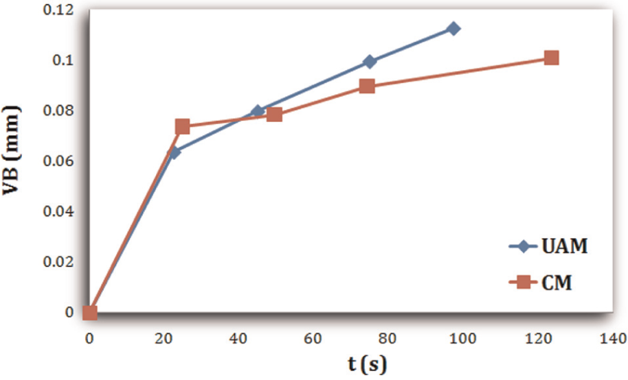
Time history of flank wear land width at n = 2000 r/min in CM and UAM processes.
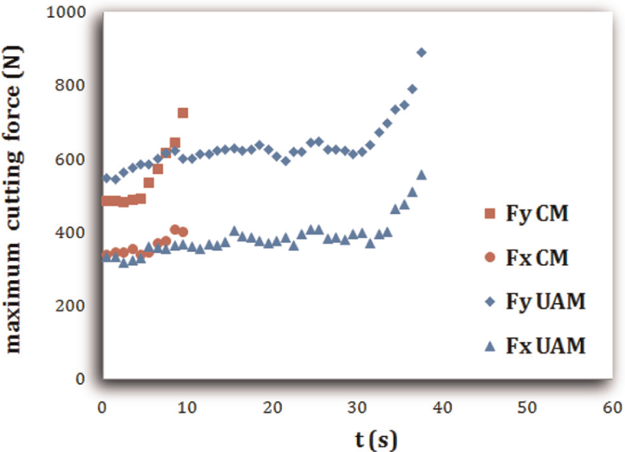
Maximum normal cutting force (Fy) and maximum feed cutting force (Fx) in CM and UAM processes with n = 3150 r/min.
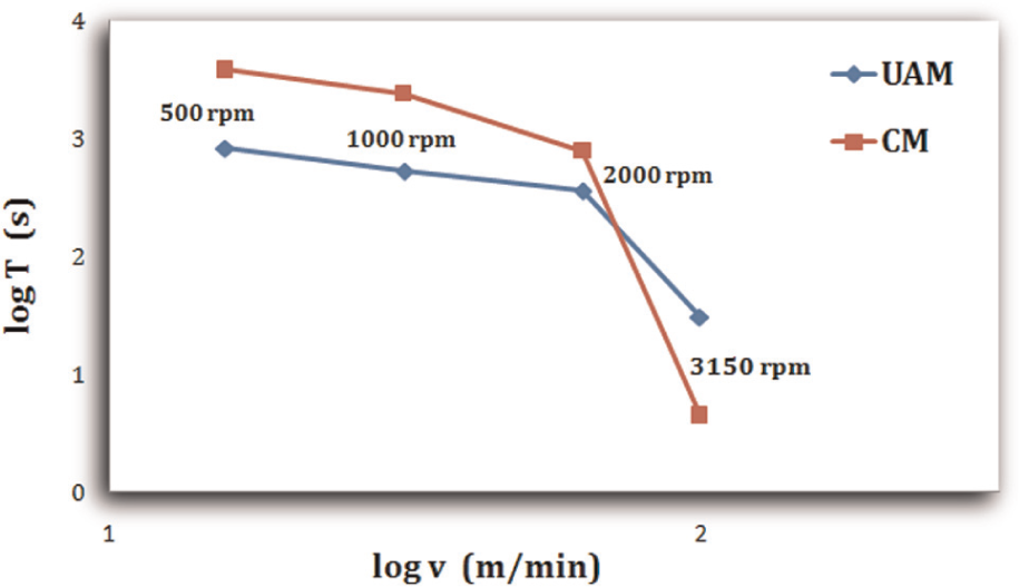
v–T curves (logarithmic scales) in CM and UAM processes, with fz = 0.1 mm/tooth, ar = 2 mm, f = 23 kHz, and a = 28 µm.
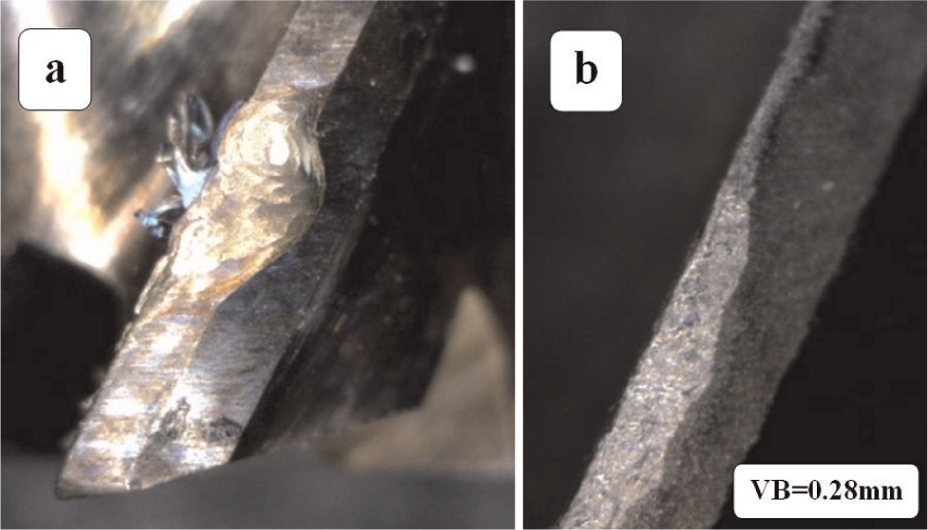
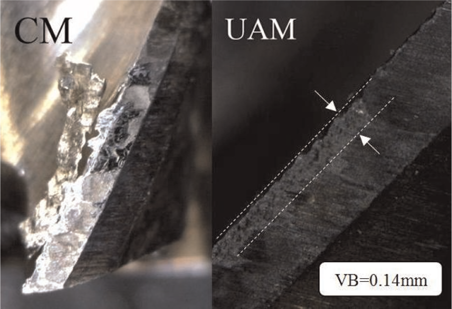
(a) Plastic deformation of cutting edge in CM process after 10 s of machining; (b) wear of tool in UAM process after 30 s of machining, with fz = 0.1 mm/tooth, ar = 2 mm, f = 23 kHz, a = 28 µm, and n = 3150 r/min.
The time history of flank wear land at n = 1000 and 2000 r/min has been shown in Figures 9 and 10, respectively. At spindle speeds of 1000 and 2000 r/min, tool wear in UAM is also higher than that in CM. It should be noted that at n = 2000 r/min, wear graphs approach each other, but it is again higher in UAM process due to impact contacts of workpiece to tool flank surface.
The tool wear graphs at n = 500, 1000, and 2000 r/min were used to determine tool life. At spindle speed of n = 3150 r/min, tool is worn rapidly in CM process and continuing to machining leads to rapid tool failure. Due to rapid wear of tool in CM process at n = 3150 r/min, the accurate calculation of tool life from graph of tool wear is not possible. Therefore, at n = 3150 r/min, the time history of maximum cutting force has been used for determining the exact tool life. Figure 11 shows maximum normal cutting force (Fy) and maximum feed cutting force (Fx) in CM and UAM processes at n = 3150 r/min. The initial instant of rapid growth of cutting force has been considered as excessive wear and end of tool life.
Figure 12 shows the logarithmic view of v–T diagram for comparing tool life in CM and UAM processes, where v = πDn is cutting speed and T is tool life. At spindle speeds of n = 500, 1000, and 2000 r/min, tool life in UAM is less than that in CM, but for n = 3150 r/min, tool life in UAM becomes considerably larger than that in CM. Therefore, adding ultrasonic vibrations can improve tool life only for n = 3150 r/min. Equation 9 and Figures 2–5 showed that increase of spindle speed reduces workpiece impacts on tool flank surface, which is totally compatible with experimental observations.
Another point in Figure 12 is the uniform decrease in tool life with the increase of spindle speed from n = 500 to 2000 r/min, whereas tool life reduces more rapidly as spindle speed increases from n = 2000 to 3150 r/min. The underlying reason for this behavior is the change of wear mechanisms. At lower spindle speeds, due to lower cutting temperature, the dominant wear mechanism is mechanical. At these speeds, due to mechanical and wear contacts between workpiece and flank surface in UAM, tool life is less than that in CM process; because of intermittent separation of workpiece and tool, temperature at cutting zone in UAM is lower than that in CM process.4,5
At n = 3150 r/min, according to equation (9), workpiece impact exerted to tool is reduced, and cutting approaches continuous state. In this spindle speed, the dominant mechanism in tool wear is thermal mechanism due to high temperature of cutting zone. Despite lateral impacts in UAM process, the higher tool life at n = 3150 r/min in UAM process implies reduced temperature of cutting zone in UAM when compared to CM process. During tests at n = 3150 r/min in CM process, due to extreme heat, cutting tool after a few seconds became red and plastic deformation happened; however, in UAM process, chip removal continued for about 40 s. Adhesive and abrasive wear are the most significant types of wear at lower cutting speeds. At high cutting speed, temperature-activated wear mechanisms including diffusion, chemical wear, and thermal wear occur. When low cutting speeds are utilized, there is a greater chance that a built-up edge condition will occur. At the other extreme, using high cutting speeds, there is a high probability that the insert will be plastically deformed. At intermediate positions, several wear mechanisms can occur simultaneously.
One of the main reasons for reduced temperature in UAM than in CM returns to change in friction coefficient from semistatic to dynamic, 21 which indeed results in reduced friction coefficient in UAM process and change in chip formation mechanism. Zhou et al. 22 pointed out that in ultrasonic vibration cutting, instead of static friction between the tool and the workpiece, dynamic friction will be generated and the friction between the tool and the work-material will be reduced. Lucas et al. 23 studied the ultrasonic cutting of three very different materials. They found that the coefficients of friction were significantly reduced by ultrasonic excitation but unaffected by ultrasonic amplitude.
Figure 13 shows the tool cutting edge at fz = 0.1 mm/tooth, ar = 2 mm, f = 23 kHz, a = 28 µm, and n = 3150 r/min after 10 s in CM and after 30 s in UAM processes. It is obvious from the figure that cutting edge and tool flank surface underwent a plastic deformation after 10 s in CM process, but after 30 s of UAM, no plastic deformation occurred. It can be deduced from Figure 13 that at spindle speed n = 3150 r/min, tool temperature in UAM process reaches its critical value in a later time than in CM process.
Conclusion
At spindle speeds of n = 500, 1000, and 2000 r/min, tool wear in UAM process is more than that in CM process. At these speeds, unfavorable impacts of workpiece to tool flank surface and, subsequently, mechanical and wear mechanisms are the main factors for rapid tool failure in UAM process. The given analytical relation and the presented graphical results also show that as spindle speed is reduced, more effective impacts are exerted from workpiece to tool flank surface. Moreover, by increasing the spindle speed, the contact of tool to workpiece is also increased in each vibration cycle, and cutting approaches a continuous form, and consequently, the amount of impacts to tool flank surface is reduced.
The experimentally obtained time history of tool wear also confirms this and shows that the difference between tool life in CM and UAM process is reduced as the spindle speed is increased from n = 500 to 1000 r/min and from n = 1000 to 2000 r/min. At n = 3150 r/min, tool life in UAM is longer than that in CM process. By adding ultrasonic vibrations to milling process at n = 3150 r/min, in addition to less impact contacts of workpiece with tool, which has been analytically shown, temperature of cutting zone and the amount of tool plastic deformation are less than those in CM process, which subsequently results in longer tool life. The change in friction coefficient from semistatic to dynamic mode, which indeed results in change of chip removal mechanism, is responsible for lower cutting zone temperature in UAM process.
Footnotes
Appendix 1
Declaration of conflicting interests
The authors declare that there is no conflict of interest.
Funding
This research received no specific grant from any funding agency in the public, commercial, or not-for-profit sectors.