
Abstract
This article proposes a scheme for functional specification in accordance with the new generation of geometrical product specification. The scheme is to decompose a geometrical functional requirement on a complex mechanism into geometric specifications defined on key parts. The assembly is analyzed by graph theory. The general geometrical functional requirement is analyzed and decomposed if necessary, with geometrical tolerances specified on ending parts. Then geometric variation model is built according to the invariant degree of freedom of both datum reference system and tolerance zone, which is subsequently used to validate the sufficiency of the datum reference frame on positioning features, thereby inferring joints that perform key roles in affecting function. After a series of topological rules formulated and validation algorithm applied, datum reference system is validated and detailed specifications are generated on joint surfaces. Those specifications on underlying parts or subassemblies are then defined as new geometrical functional requirements and should be further developed. Therefore, the designer can carry out an effective recursive approach capable of realizing each geometric specification on key features while ensuring functional tolerancing of the entire assembly. A case study is given to validate the proposed method.
Keywords
Introduction
Tolerancing is an important task in product design since design tolerances strongly influence the functional performance and manufacturing cost of a mechanical product. In traditional tolerancing design process, the major work of a designer is to determine a proper linear tolerance value for every part. However, along with the increasingly competitive market environment, a higher accuracy of the product cost control is demanded. As a result, the linear tolerance no longer meets the requirement of modern product design. 1 Modern technical standard (ASME Y14.5:2009) 2 has included a set of standards considering geometrical tolerance, encouraging designers to apply geometrical tolerance into practical production process to ensure assembly success rate and products’ functional requirements. The use of geometrical tolerance causes a series of complicated problems compared with the linear tolerance. When linear tolerance is specified, the functional dimension is only but to consider, which is usually the distance between surfaces or other geometric entities (axis, edge, point, etc.). However, when it occurs in geometrical tolerance specification, various kinds of geometric characteristics are needed to be controlled including those of form, orientation, position and run out, which result in the significant increase of the complexity.
In three-dimensional (3D) tolerance design processes, detailed geometrical specification, including identifying function influential features on assembly, searching for 3D tolerance chain and determining tolerance type and tolerance principle, and so on, is required before tolerance allocation. When the specification activity is carried out, effectiveness, sufficiency and consistency should be taken into consideration as acceptance criteria of final specification. 3 Also, distinctive assumptions should be made to accommodate different applied engineering fields. For example, the choice of datum reference frame (DRF) would be very different in specifying parts of rotating mechanical assemblies and specifying assembly of thin wall components. Moreover, the choice of proper tolerance value should be considered in advance, so that the designer can take the economic factors into account in the early stage and reduce the cost and the risk of redesign. 4
Geometrical specification nowadays mainly depends on designer’s experience, lacking systematic, explicit and rule-based scheme, which usually leads to ineffective design process and inconsistency. To cope with this situation, some research work has been carried out. A commonly cited model is based on technologically and topologically related surfaces (TTRSs). Clément et al., 5 Salomons, 6 Salomons et al. 7 and Houten et al. 8 have built models of TTRS on surfaces based on an invariant class and minimum geometrical reference elements (MGREs) and found topological relations between surfaces in order to determine DRF and tolerance type that confine relative relationship between surfaces. Shah et al. 9 and Wu et al. 10 have developed a representation model based on degrees of freedom (DOFs) of geometric entities, which are later linked by metric relations. Various combinations of entities are classified, and then a method has been provided to convert constraints on DOF to tolerances. Wang et al. 11 have proposed an approach called mirrors, referring to the planar surfaces in assembly joints. Strong mirrors and weak mirrors are classified depending on whether the contact relation has a minimum of three actual contact points. Functional features of every influential part will be clustered according to their adjacency to mirrors, and then datum feature will be selected from the cluster and parts will be toleranced with priority by rules. Anselmetti and Mawussi 12 and Mejbri et al.13,14 have developed an efficient method with positioning tables in tolerance specification, avoiding considering the whole graph of relations among part features in an assembly. Variational geometric constraints network for assembly has been presented by Hu et al., 15 and concepts of mate tree and loop circuit are put forward. Types of variational geometric constraints are classified, and relations between tolerances and constraints are built to help develop specification chains on assembly.
Based on theoretical research above, some computer-aided tolerancing software have been developed and put into business market. CETOL 6σ 16 developed by Sigmetrix builds tolerance model based on kinematic joints in the assembly and carries out tolerance analysis by searching vector loop and transferring small displacement torsor matrix; VisVSA 17 is a powerful dimensional analysis tool, which is used to simulate manufacturing and assembly processes and predict the amounts and causes of variation by Monte Carlo simulation. It can validate the tolerance value, yet it is not able to validate DRFs; 18 3DCS 19 is a tolerance simulation tool that allows users to model the effect of variation on any assembly, determine the robustness of the design and test alternative tolerancing schemes. Many other commercial software packages have been designed to carry out similar functions. Most of the current software applications are capable of analyzing the accumulation of tolerance and predicting the variation, yet lacking a detailed and thorough specification scheme, especially when dealing with tolerance with datums. Also, the specification chain cannot be autogenerated.
This article aims at developing a systematic and effective scheme applying to tolerance specification on complex mechanism. The functional requirement of the assembly mechanism is looked into, analyzed and then decomposed. Positioning joints are focused on searching for key parts and key features. Key features are points, lines and surfaces, whose variations deeply affect the assembly and function of products. After key features have been identified, DRF and tolerance type could be automatically defined on parts in the interface. The detailed procedure of the scheme will be presented in the following sections, and later an example of propeller shaft is given to help elaborate the scheme.
Functional specification scheme on interface
In the specification processes, one major task is to identify key parts and key features inside the complex assembly. Those key features, where the tolerance should be specified, affect the final function of the products. As a result, the structure of the assembly should be first analyzed. Based on the structural information, this article proposed a method of constructing geometric variation model of both tolerance zone and DRF to help validating DRF and therefore inferring key features, which will be illustrated in the following sections.
Geometrical variation model of tolerance zone
Tolerance defined on the surface or its derived feature limits the geometrical variation of the surface in space. The scope of the variation is called the tolerance zone. A tolerance zone is defined by four aspects including size, form, orientation and position. Size of tolerance zone is determined by the tolerance value, while the other three aspects of tolerance zone are corresponding to both the attribute of specified surface and the tolerance type.
Uncertainty exists in the orientation and position of the tolerance zone, which can be characterized by the degree of invariance. Form tolerance does not need datum feature, so its tolerance zone is floating, with both orientation and position being uncertain; degree of invariance of orientation tolerance and position tolerance needs to be determined by topological attributes of specified surface and tolerance type. Models of tolerance zone for those tolerances with datums should be built. Mejbri et al. 14 studied a tolerance zone model based on vectorial representation. The formalization of some topological rules is detailed here.
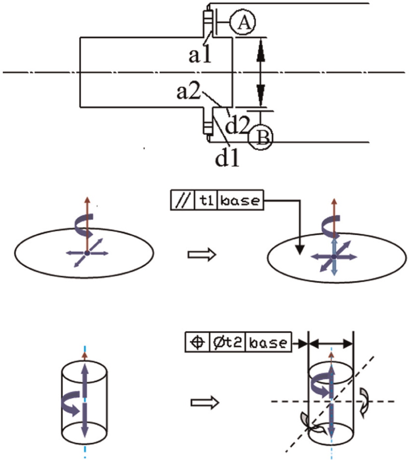
As is shown in Figure 1, the bottom plane is a datum surface, and perpendicularity is specified on the left surface. The tolerance zone is the area between two parallel planes perpendicular to the bottom plane.

where the DOF of the specified feature (or its derived feature) equals that of the tolerance zone where the specified feature is. It is easy to recognize the constrained direction of the specified feature by analyzing the tolerance zone.
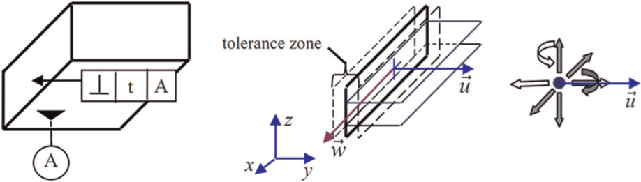
Model of tolerance zone.
DRF validation
Single surfaces relate to each other in a combination and form a TTRS; two TTRSs can also combine into a new TTRS. Every TTRS can be represented by one exclusive MGRE. According to the concept of symmetry, TTRS can be classified into seven invariance classes as shown in Figure 2. 16
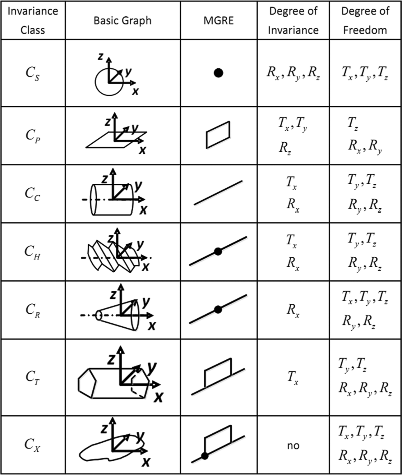
Invariance classes.
Based on the theory of TTRS and MGRE, the geometric variation models of both tolerance zone and DRF are built based on invariance degree. Analysis of the two variation models can help validating DRF, indirectly inferring key features.
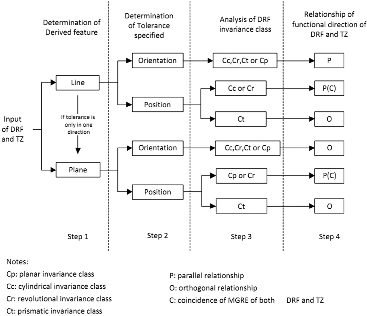
In accordance with the concept of TTRS, several TTRSs can be regrouped and formed into a new TTRS that belongs to one of the seven invariance classes. A DRF can be treated as a TTRS after regrouping. Comparison between the geometric variation model of DRF and the tolerance zone helps to validate a DRF. A valid DRF has a certain topological relation with the tolerance zone. The invariance degrees that DRF limits must include the functional direction of the specified feature, which also represents the range of variation of the specified feature. So a set of topological rules are proposed to help valid a DRF as delineated in the flow graph (Figure 3). Four steps are involved in topological rules:
Step 1:
the feature specified is looked into and distinguished by its derived feature, that is, line (axis, edge) or plane.
DRF validation flow graph.
One special case should be noted: if the tolerance on a line is specified only in one direction, the tolerance should be equally treated as tolerance on specified feature whose derived feature is a plane. In this case, one should refer to the “plane” category for latter validation steps. As is shown in Figure 4, the axis of a cylindrical surface is specified without symbol
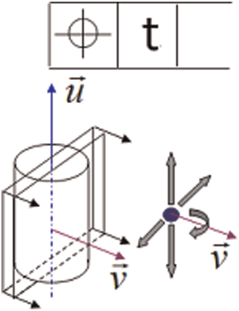
Special case in validation flow.
Step 2:
tolerance type should be distinguished (orientation or position).
Step 3:
TTRS of a DRF should be analyzed and invariance degree of a DRF should be obtained. It occurs that only certain types of TTRSs (out of seven invariance class) are possible to qualify a valid DRF, depending on specific cases during the last step. For instance, when a position tolerance is specified on a feature whose derived feature is a line, the related DRF should belong to Cc, Cr or Ct class to be valid.
Step 4:
According to each case developed in step 3, relationship of functional direction of both DRF and tolerance zone is given, which a DRF must require for its validity. Symbols P and O mean parallel and orthogonal relationship of functional directions of DRF and the tolerance zone, respectively, and symbol C means MGREs of both DRF and the tolerance zone should coincide.
Designers should follow these four steps in sequence to validate the DRF. In addition, a DRF of a compound class of invariance is always a valid DRF. Detailed illustration with an example using these topological rules is further developed in the latter section.
During the DRF validating process, the redundancy of the DRF that may cause overconstrained should be avoided. The selection of the initial DRF depends on the analysis of joints on the interface, in consideration of the preponderance of the joints based on the number of restricted DOFs. The initial selected DRF usually has three datums: primary datum A, secondary datum B and tertiary datum C. The validation of a DRF should be in the order of DRF A to DRF A-B to DRF A-B-C. Once a DRF is valid according to the rules proposed above, the validation process ends and the DRF is picked. If none of these three DRFs is valid after the process, then return to the beginning and reselect the initial DRF.
Functional specification scheme
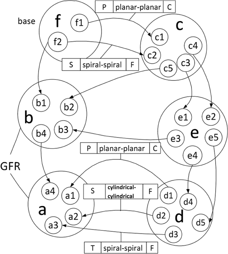
In the whole specification process, the structure of the complex assembly will at first be looked into and analyzed to get the detailed information of connection between parts. The general geometrical functional requirement (GFR) should be indicated and decomposed if necessary. All positioning features and their contact/fit information should be expressed clearly, along with the preponderance of the joints. Also, it is helpful to consider the invariance classes of two assembling functional features on the interface, in order to instruct the selection of datums. The assembly model based on the graph theory is a useful tool to analyze the mechanism. Based on the assembly oriented graph (AOG), 10 some improvements are made to express the assembly information, as illustrated in Figure 5.
In Figure 5, every big circle (referred as node) represents a part, while the small circles inside the big circle represent functional surfaces of the part; arrows on oriented arcs point to the positioned part (pointing from the lower part to the upper part), each oriented arc representing an assembly positioning joint; property information is on every oriented arc (representing the property of assembly positioning joints), including the preponderance order of assembly positioning joints (primary, secondary or tertiary), the invariance class of two assembling functional surfaces forming an assembly positioning joint and also the information of contact/fitting.
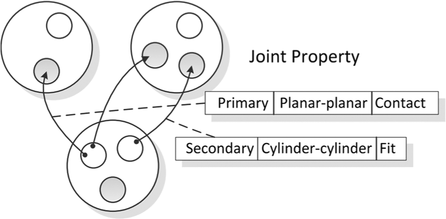
Improved assembly oriented graph (AOG).
Using the improved AOG, the assembly order of parts and interface information are described. An important procedure is to determine key features where tolerance is specified. Key features play an influential role in transmitting function. As a DRF of one part (upper part) is connected to another part (lower part), it not only affects the upper parts specification but also acts like a medium in transmitting function to the lower parts. The features where the DRFs locate should be considered as key features. In that case, the validation of a DRF indirectly determines key features. As the variations on lower parts could affect upper parts or subassemblies, geometrical requirements of lower parts should be dealt with, which are derived from the function transmission by the DRF on key features. Specifications are obtained by decomposing specification on the upper part, which are then considered as a new GFR, and the lower part becomes a new upper part for the later specification process. In such a way, a recursive design approach is carried out.
Figure 6 shows the functional specification scheme for a complex assembly. The flow begins from assembly analysis. Functional parts and features, base part and ending part and features connection and joint property are all expressed using improved AOG. Then the general GFR is analyzed. If the GFR is a requirement between multiple ending parts, it will be decomposed into each single requirement between each ending part and the base part. Then initial specification on the ending part is carried out. For each requirement, a specification chain will be developed on key features. Geometric variation model of tolerance zone and DRF helps to validate a DRF and infers key features, in accordance with a set of topological rules. Then the tolerance type, tolerance item and tolerance principle could be determined. By function transmission through the DRF on key features, specifications on the lower part become new geometrical requirements. A recursive specification method is performed until specifications reach the base part. Further study and detailed specification process are illustrated in an industrial example in the next section.
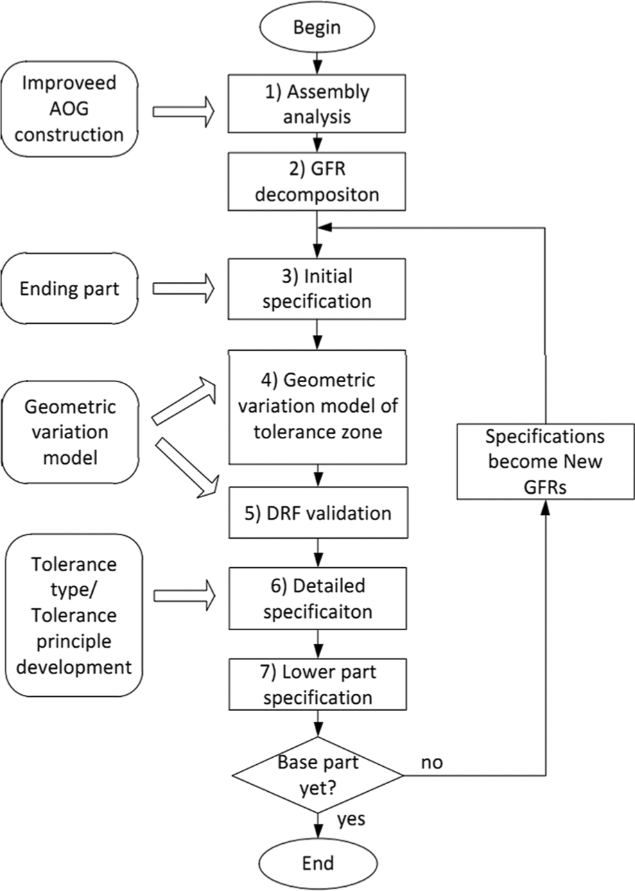
Functional specification scheme.
Case study
Figure 7 is part of a propeller mechanism. An assembly of a propeller shaft is located in the housing with an oil distributor at the head of the shaft. For the later functional specification, for the sake of expressing convenience, the assembly engineering drawing is simplified to give the relative relationship between each part. The assembly contains the following parts: (a) oil distributor, (b) bearing end cover, (c) bearing sleeve cup, (d) propeller shaft, (e) trust roller bearings and (f) housing. To start the process of specification, the assembly analysis should be first conducted. Figure 8 denotes functional surfaces on the whole assembly. The improved AOG is given to help analyze the connection between each part (Figure 9).
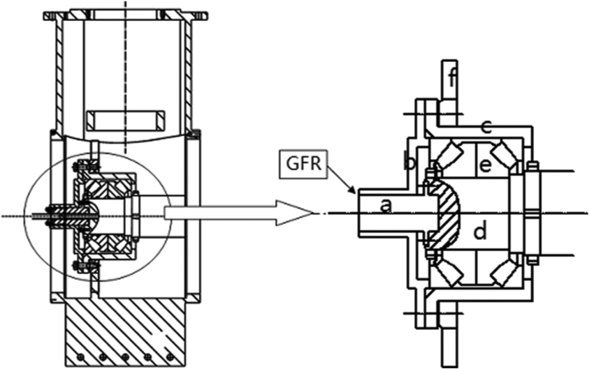
Engineering drawing of the assembly propeller shaft mechanism.
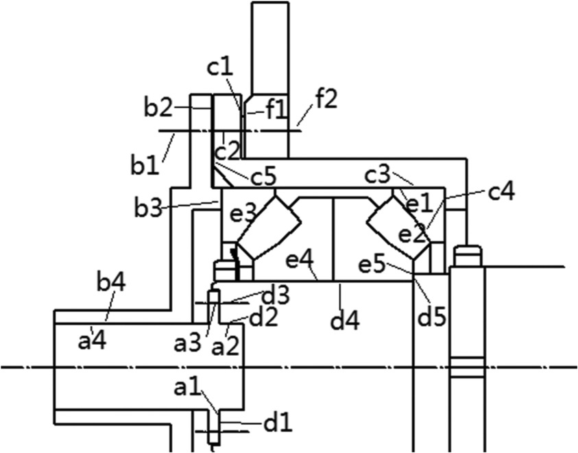
Functional surfaces on every part.
Detailed description of the assembly.
The oil distributor’s working condition requests clearance requirement between the distributor and the bearing end cover, which is defined as GFR. Since this GFR, the radius distance, is between two end parts, it should be decomposed into GFR1 (between part a and the base) and GFR2 (between part b and the base) (Figure 10).
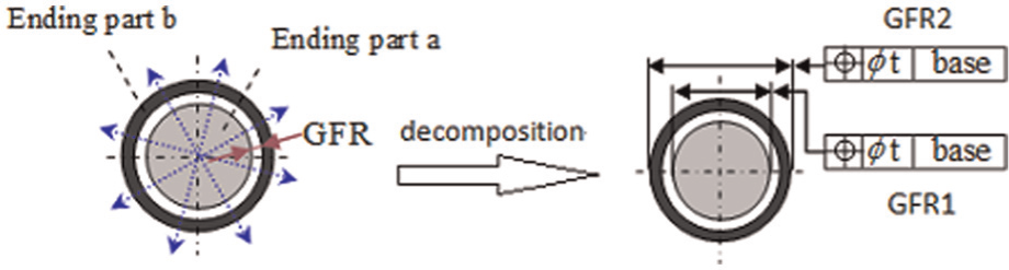
GFR decomposition.
To begin with, the GFR1 between the ending part a and the base is investigated. The initial specification is carried out first. After the decomposition of GFR, a position tolerance is specified on the surface a4 (its derived feature) of part a. Surface a4 is cylindrical, whose geometric variation model is built as shown in Figure 11, and it has a translational invariance degree along z axis and a rotational invariance degree around z axis as depicted.
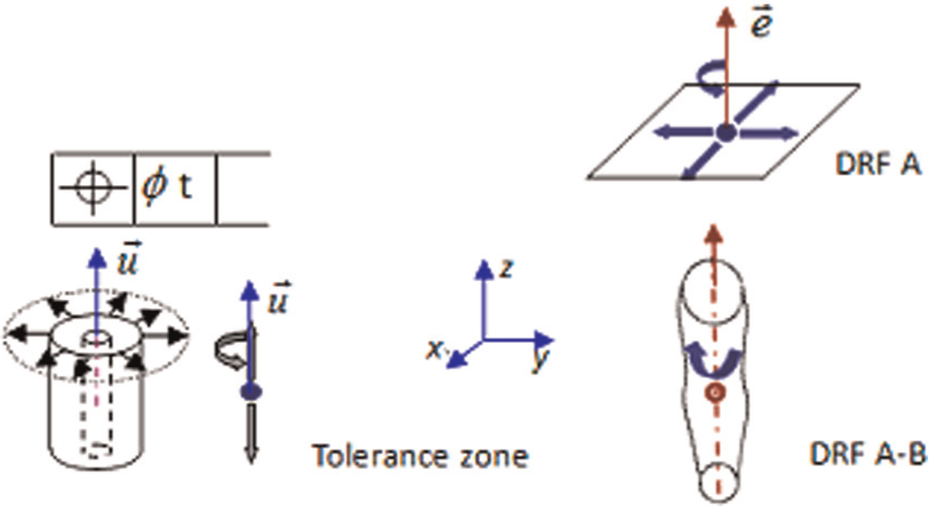
Geometric variation model for tolerance zone and DRFs.
Then geometric variation model of DRF needs to be built. The initial DRF A-B-C is selected with three datums in preponderance order based on the constrained number of DOFs (see Figure 12). DRFs are selected in the order of A, A-B and A-B-C to be validated. DRF A is taken into consideration first, whose invariance degree is depicted in Figure 11 with two translational invariance degree along the x and y axes, respectively. This DRF does not conform to topological rules above, so a datum is added to form a new DRF. DRF A-B is examined next. The plane where datum A is located and the cylindrical surface where datum B is located have formed a revolutional TTRS with an invariance degree around z axis (Figure 11). DRF A-B conforms to topological rules. Therefore, DRF A-B is sufficient for the specified tolerance, and DRF A-B-C is no longer necessary to be examined. The final specification of part a after DRF validation is presented in Figure 12.
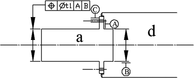
Datum reference frame (DRF) validation on the interface.
From the validation of DRF, the surface a4 has been specified on part a, while the key feature planar surface a1 and cylindrical surface a2 are inferred (Figure 13). The features on the lower part d connecting (fit/contact) to a1 and a2 are surfaces d1 and d2, which are to be specified later.
Function transmission from upper part to lower part.
Surface d1 in the primary joint is specified first (Figure 13). The plane d1 originally contains translational invariance degree along x and y axes and rotational invariance degree around z axis. Those constrained DOFs, which are the same as the invariant degrees of the specified feature on the upper part, should be added to form new DOFs to infer whether position or orientation tolerance should be specified. By this rule, according to the invariant degrees of a1, translational DOF along z axis is added to form new DOFs combination, from which it is deduced that only orientation tolerance (parallelism) should be specified on d1 (Figure 13).
Then cylindrical surface d2 is specified. The same process is performed, and the new combination of the DOFs is shown in Figure 13. Since the orientation tolerance has already been specified on the primary joint, here on d2 the position tolerance is needed. The specification of the lower part d is presented in Figure 14
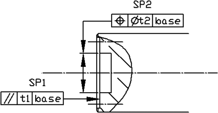
Specifications on the lower part.
From the initial GRF on part a, we have decomposed it from the upper part a into two specifications (SP1, SP2) on the lower part d. SP1 and SP2 are separately treated as new GRFs to transmit the geometrical requirement and carry on specification to the next part to be specified.
The GFR2 between the ending part b and the base can be processed in the same method described above. The specification order of all parts, according to the function transmission, will be formed as shown in Figure 15. Note that the barring e is a standard part that does not need to be specified on, yet, it assumes the role in transmitting the function and need to be analyzed as other parts using the method above.
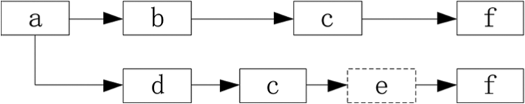
Specification order of parts.
With the recursive method, the initial GFR can be decomposed into several sub-GFRs and specification can be carried on. Tolerance items and tolerance principles are then applied. The final specification of the whole propeller shaft assembly is represented as Figure 16. The whole specification scheme is sequential and effective and is suitable for the computer-aided design (CAD) integration.
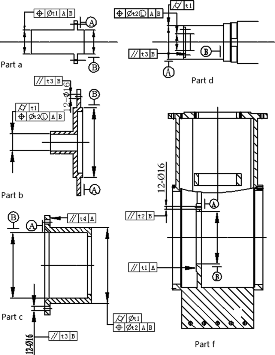
Specification of all parts of an assembly.
Conclusion
The article intends to construct a complete and effective scheme for functional tolerance specification on a complex assembly. A method for building specification chains while searching key parts and key features in the assembly is proposed. Assembly analysis using improved AOG is first performed, expressing relations between each parts and features. Then the initial GFR is analyzed and decomposed to the specification on the key parts. Geometric variation models are built and topological rules are made to valid DRFs, inferring key features to transmit function. Considering the specification on the lower part of the new GFR, a recursive process is performed until specifications reach the base part.
Footnotes
Funding
This research was supported by the National Natural Science Foundation of P. R. China (No. 51275464), the National Basic Research Program of P. R. China (973 Program, No.2011CB706505) and the Science Fund for Creative Research Groups of National Natural Science Foundation of China (No.51221004).