
Abstract
The digital twin concept, as a widely accepted philosophy for a new generation of digital manufacturing research, plays a significant role in the Industry 4.0 era. As the prerequisite for in-depth application of digital manufacturing in assembly, the collecting, modeling and utilizing approach for historical data of machining process and inspection of part appear to be important to provide data support for integral manufacturing scenarios. However, the modeling approach to part digital twin is not comprehensive due to the structural heterogeneity of data, which hampers the real-time simulation and adjustment in assembly process. Therefore, a method of part digital twin modeling oriented to assembly is proposed in this article. The designing information of a part is obtained from a three-dimensional model with the model-based definition approach, while machining features are pre-defined and identified. Moreover, the assembly constrain relationships in the assembly unit that the part participate in are obtained, on account of which deviation transfer analysis can be accomplished, and key assembly features are filtered to be the carrier of processing and inspection data. An assembly-oriented part digital twin framework is constructed to demonstrate the main components and dataflow in creating a digital twin with information filtering and subsequent management. In addition, a case study is illustrated to show the entire process of part digital twin modeling and proves the practicality and efficiency of the method proposed.
Keywords
Introduction
With the development of digital manufacturing technology and the requirements of Industry 4.0, digital twin concept has received worldwide extensive attention and is being rapidly exploited by industry innovations. The idea of the digital twin was proposed first by Grieves and Vickers 1 as a set of virtual information constructs that fully describes a potential or actual physical manufactured product. In order to achieve this goal, the modeling of digital twin and the establishment of the bridge between digital twin model and physical world become fundamental issues. 2
Meanwhile, the connectivity, modularity and autonomy of digital twin also challenge the modeling approach in the lifecycle of a product. 3 Particularly, the assembly phase of a product is full of uncertainties and real-time requirements, which demand the digital twin of assembly workflow to be more structured and contains more comprehensive data. In general, most of the information in an assembly unit4,5 is carried by the parts involved in the assembly. Namely, the part digital twins submitted simultaneously with delivering will determine the construction of assembly unit information model to a large extent and affect the information flow in assembly phase.
Some studies have investigated the method of the modeling approaches to digital twin. Most studies have revolved around a three-dimensional (3D) digital twin model defined by Grieves and Vickers 1 , and Grieves6–8 which consists of physical entity, virtual equipment and the connection between virtual and real world. On this basis, Tao et al.2,9–11 proposed a five-dimensional digital twin model as a supplement and extension. They considered the services and data and expanded the connection among them additionally to encapsulate the functions of a digital twin. Furthermore, the content of a digital twin model is also increasing with the continuous development of digital technology and the increasing number of digital means. Stark et al. 12 provided an eight-dimensional digital twin model with the target of a digital twin solution for a smart factory cell. They advocated that eight aspects should be considered to build and maintain a living digital twin, including integration breadth, connectivity modes, update frequency, cyber-physical systems (CPSs) intelligence, simulation capabilities, digital model richness, human interaction and product lifecycle.
In addition to the methodology mentioned above, the specific applications of constructing digital twins has been invested a lot of energy by researchers from the level of parts and products. Schroeder et al. 13 proposed a cogitation of data modeling with automation markup language (AutomationML) premeditating different types of product models created in lifecycle, such as 3D geometric models, multiphysics models and manufacturing models. They also considered a communication methodology for data exchange among different models. Furthermore, Sierla et al. 14 established a 3D simulation environment using AutomationML as well for digital product descriptions, leading to a collaborative and interactive network-centric process of product design and process planning. Bao et al. 15 presented process digital twin as 3D models throughout the manufacturing process, including manufacturing procedure model, process attribute information and asset digital twins. Process digital twin was described with AutomationML and complemented the digital twin of a part with historical processing information. Schleich et al. 16 provided a comprehensive reference model based on the concept of skin model shapes to be a digital twin of a product describing the actual processing results, which is effective in supporting information storage and analysis. Miller et al. 17 attempted to enhance the computer-aided design (CAD) model with spatially related non-geometric data. By rereading and organizing non-geometric data, consumers can utilize information without specific CAD tools, which put forward a new idea about part modeling. To solve the problems of product health monitoring, maintenance, fault diagnosis and quality prediction, various models of parts and products have been established and discussed,18–23 such as finite element analysis model, Modelica multiphysics model and statistical model. Meanwhile, product lifecycle data and digital twin of machining workshop have been extensively researched24–27 with the purpose of creating a data circulation environment for parts and products catering the tendency of smart manufacturing.
Apart from the information modeling based on AutomationML, unified modeling language (UML) and systems modeling language (SysML), semantic web language such as ontology web language (OWL) and Apache Jena were brought into the modeling process. 28 Especially, OWL-based manufacturing tools, equipments and services modeling has been extensively researched,29,30 which prove the growing importance of semantics in manufacturing area. The ontology-based method could have certain advantages in modeling of static discrete information with merging and/or clustering on account of the semantic consistency and abundance. 31
The literatures mentioned above fully prove that the digital twin modeling is of great significance in the research of realistic digital twin technology. Due to the development of modeling technology and diversity of modeling languages, digital twin modeling has been widely developed, which lead the establishment of digital twin framework and the application of digital twin to certain extent. However, the modeling and application of part digital twin were not consummate in assembly view according to the existed research findings. In the circumstances of distributed manufacturing, outsourced manufacturing services are appearing to be dominant in the supply of the parts. 32 The investigation shows the current situation that part manufacturers and assembly workshop of one product generally belong to two or more sets of production systems, resulting in serious information inequality. With the increasing quality requirements of assembly product, assembly workshops demand more detailed manufacturing information of parts as a supplement of quality evaluation reports. However, a structured and concise part information model is needed by part suppliers to save information transfer costs.
Based on the foregoing observation, the current applications of digital twin did not provide an effective solution in expressing part information. Motivated by this need, this article proposes an ontology-based modeling method of part digital twin oriented to assembly with reduction of data entries and precondition for analytical needs. With the definition and identification of machining features, key assembly features are abstracted as the prioritized carriers of processing and inspection data. An ontology is developed to pre-define the information architecture of digital twin with the establishment of the modeling framework. In addition, a case study of the application is presented.
Definition and identification ofmachining features
Machining features generally differ from the designing features in a part during designing and manufacturing process because of the isolation of these two sections in workshop. 33 In order to record process information uniformly, machining features should be the junctions between a part and this part’s process information.
Fortunately, ISO 14649 34 has provided integral and standardized definition of machining features. In accordance with the definition of ISO 14649, all machining features are divided into seven types: planar face, pocket, slot, step, hole, generic feature and compound feature as they are suitable for different kinds of machining equipments, tools and parameters. Each type of machining features has unique attributes to describe the basic shape of itself.
With the development and popularization of CAD, the designing intents and requirements of parts are usually reflected in the model-based definition (MBD) designing models. Graph theory, as one of the most successful approaches of feature recognition, 33 is used as reference in decomposing and re-expressing geometric information of machining features and parts in this article.
Take the type of pocket as an example, the basic shapes of pockets are shown in Figure 1 with subgraphs that re-express them with graph theory. With different bottom conditions and boundary conditions, the subgraphs of pockets should be distinct due to the diversity of geometric elements and topological relations among them. Actually, there are more than four types of pockets with different subgraphs because of the existence of chamfers and transition surfaces. Detailed pockets classification and subgraphs can be derived in the same way.
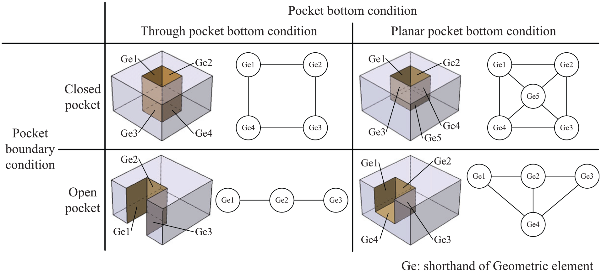
Basic shapes and subgraphs of pockets.
In addition, a part can also be re-expressed by a subgraph with the method above. The main steps of distinguishing machining features include
As usually composed of one specific geometric element, the machining feature hole can be distinguished by identifying the closed rotary surface in a part. The specific type of a hole can be determined by whether there is a bottom of it or the shape of the bottom.
Some machining features with definite expressions by subgraphs like pocket, slot and step can be identified with Ullmann Algorithm. 35
Rest of the geometric elements in a part, mostly flats, can be classified as planar face temporarily.
Finally, generic feature should be defined artificially in the case of considering the unique shape characteristics of the part, along with compound feature by consideration of combination method.
In general, machining features are machined in one process with changeless environment, which guarantees that the machining features are appropriate carriers of processing data in a part.
Reasoning of key assembly features
To improve assembly quality and increase assembly productivity, assembly workshops put more effort and costs gradually in pre-analysis for assembly process. Besides designing data and quality data, processing data become more pivotal to reflect the conditions of parts in supporting analysis.
However, processing data measure very huge in case of non-filtering, which brings additional costs in transmission and storage. Inspired by the concept of key characteristics, 36 the attempt of searching key assembly features among machining features of parts involved in the assembly is made in this article.
According to the analysis of deviation sourcing and its propagation for mechanical assembly,37,38 assembly quality and assembly yield are determined by some geometric elements of parts without the consideration of deviations from the fixtures and frocks. Naturally, the machining features comprised by those particular geometric elements become key analysis objects. Meanwhile, this article concentrates on the uncomplex structures without intricate deviation transmission path.
Geometrical information of parts and constraints in assembly units should be ontologically modeled since ontology is chosen to describe concepts and relations in this article. Figure 2 shows a set of ontology instances to support the reasoning of key assembly features, and the detailed method of modeling will be introduced in the following sections.
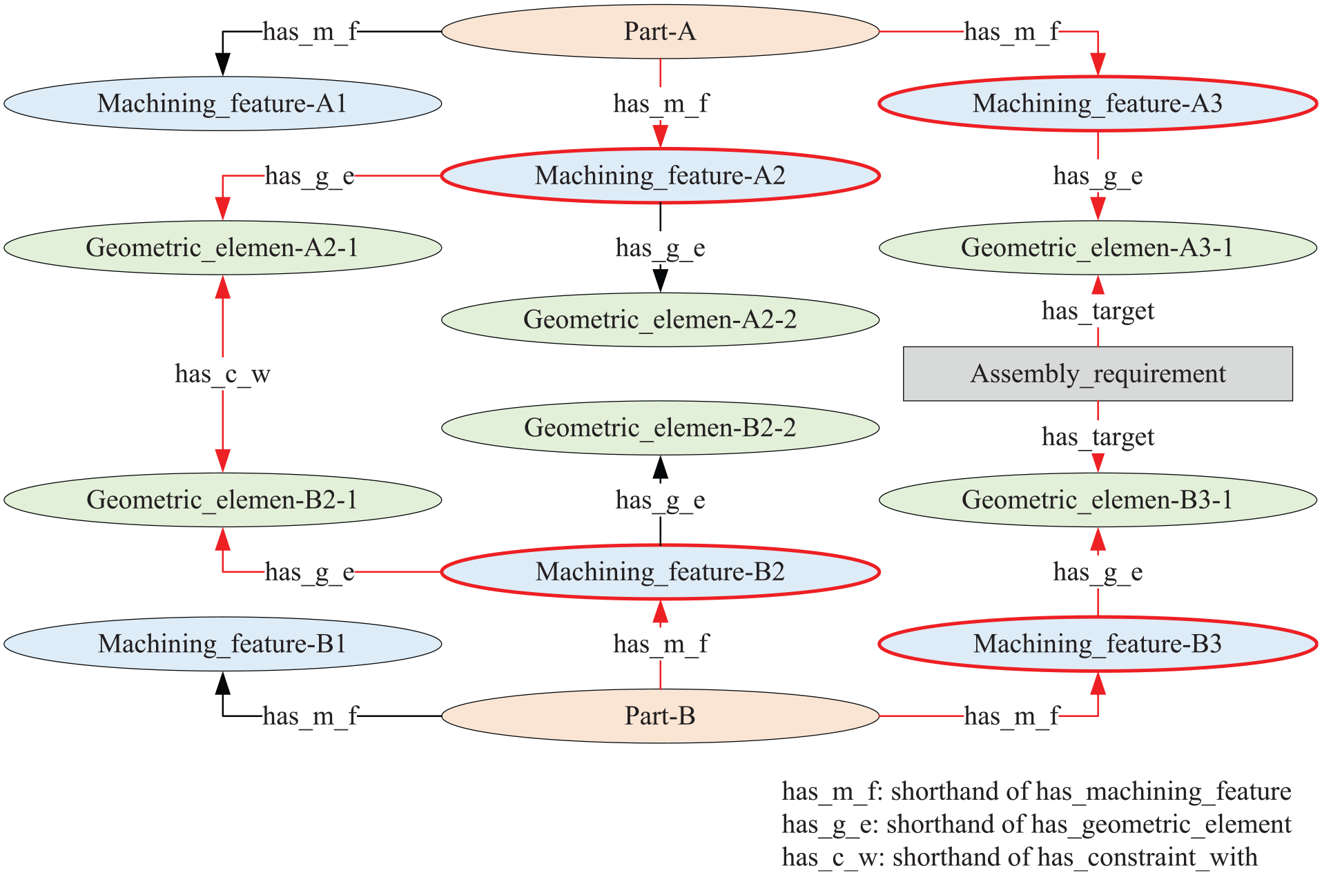
A set of ontology instances and relations as an example.
With the information modeling of parts and constraints in assembly units, series of ontology instances and relations can be abstracted. Ordinarily, one specific assembly requirement like distance and tolerance can be regarded as a regulation in fixing the position of two geometric elements. With ontological reasoning based on the rules referenced from breadth first search (BFS) algorithm, 39 key assembly features related to the assembly requirement can be obtained. To define assembly features completely, all assembly requirements in an assembly unit should be analyzed the same way. The main steps of reasoning of key assembly features are taken as follows:
Create instances of parts, machining features and geometric elements and search the relationships among them with geometric model of parts and the results of machining features identification.
For every assembly requirement, consider two related geometric elements as the starting point and ending point of the BFS algorithm. Repeat step 3 below with each assembly requirement in the assembly unit.
Deduce the path between starting point and ending point with the relationships among instances. Record the instances of machining features on the path to be key assembly features of the parts they belong to.
Due to the significant influence that positioning benchmark could bring to the processing result of machining features, the machining features which play the role of processing benchmark for key assembly features deduced above should be considered as key assembly features of corresponding parts as well.
After reasoning with all assembly requirements, all key assembly units of parts can be founded separately.
Assembly-oriented part digital twin framework
This section introduces a framework of assembly-oriented part digital twin. The establishment of the digital duplicate of a part should be resolved into three main contents: determining the methodology of information modeling, accomplishing the analysis of part information and constructing the ontology-based part digital twin.
Methodology of information modeling
The most common concept of a model is that it is a set of instructions, rules, equations or constraints for generation I/O behavior. 40 In other words, a model is built with initial state and data conversion method to output structured information based on needs. The inescapable fact about modeling is that it is severely constrained by complex limitations and data sources. Therefore, the major difficulty of modeling is how to set up a description method for structural heterogeneous data according to requirements existed.
As mentioned by Stark et al., 12 the modeling of digital twins should focus on the context, environment, behavior and capability richness of them. For the requirements of modeling in this article, part digital twins should focus on the integration breadth, connectivity modes, digital model richness and human interaction.
In recent years, standardized ontologies are developed that domain experts can use to share and annotate information in their fields. Ontology is verified to be able to share common understanding of the structure of information among people or software agents. With the advantages in describing diverse individuals and the relationships among them, ontology is able to fulfill the requirements of integration breadth and model richness. Meanwhile, connection and interaction are no longer problems because currently there are well-established language and visual editing tools for ontology. However, there is no unified modeling method yet because of the different applicabilities in mechanical domain. In this article, the seven-step method 41 proposed by Stanford University is used to develop an ontology. Figure 3 shows the iterative process of seven-step method.
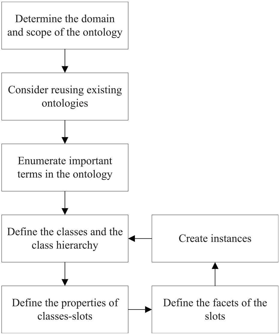
The seven-step method for development of ontology.
According to the seven-step method, the data source and primary type should be confirmed in the first place to support the development of ontology used to virtualize part information in assembly view.
Analysis of part information
When a part is delivered to an assembly workshop, the information about the lifecycle of the part so far and information sources are normally definite. At this particular point, data of the part stay stationary with series of forms and CAD models. Similar research works42,43 usually classify information of part into geometric and non-geometric information, which is unspecific with the present vision. With the consideration of data sources and structures, part information is divided into four types here, as shown in Figure 4.
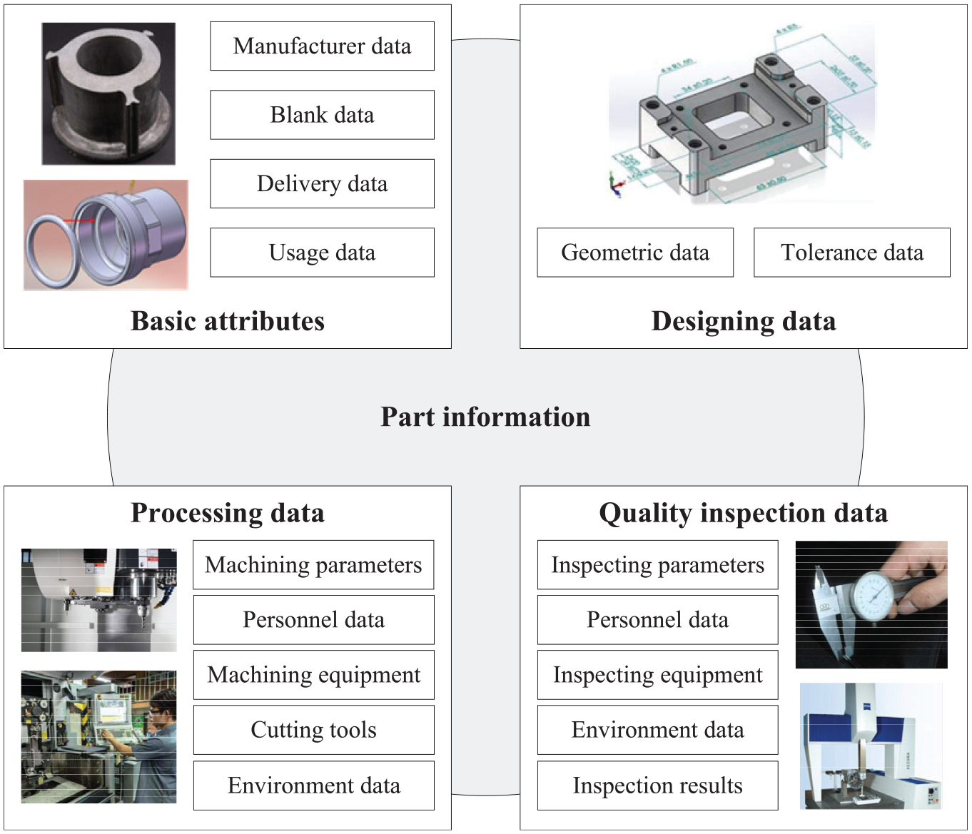
Composition of part information.
These four types of data will be ready for the part transferred to assembly workshop. To be more specific, basic attributes should involve something not related to the manufacturing itself. Supplementary data, such as manufacturer data, blank data and so on, should also be considered in constructing a digital twin. Designing data mainly reflects design intents of the part such as geometric shape, topological relationships among geometric elements and tolerances. The effect of processing data is to record details in machining process of the part. Quality inspection data are defined to depict results and processes in quality inspection. As an integral digital twin of the part, the data abovementioned should be consolidated into a single packet. However, similarity may exist when digital twins are constructed for parts produced in the same batch. Some common data entries of part digital twins can be generated concurrently under such circumstances.
As mentioned above, there is no need for a digital twin of a part to cover processing data and inspection data of all machining features. The role that a part played in an assembly unit can be informed by assembly workshop before delivering, which can help part supplier to pre-analyze the key assembly features. Thus, the amount of data of digital twin can be obviously reduced by discarding data that is insignificant in assembly.
The dataflow in constructing a digital twin is shown in Figure 5. With the deployment of manufacturing processes of a part, the corresponding digital twin can cover data from multiple sources, including enterprise resource planning (ERP) system, CAD platform, manufacturing execution system (MES), inspection planning system, on-site sensors in different scenes, logistics system, assembly planning and so on. Benefit from the extensive research of CyberManufacturing Systems 44 and middleware, 45 the data with certain semantics could perform orderly in forming digital twins. However, with the needs of data for some specific analysis in assembly, the type of data sources can be extended with the type of data being extended. With all related data flowing together, the initial digital twin is constructed that cover information sufficient to support assembly. An appropriate information structure should be accomplished for the expression of various data.
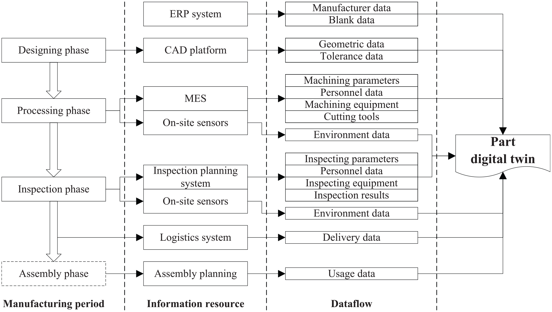
Dataflow in creating a digital twin.
Ontology-based part digital twins
To effectively organize the discrete heterogeneous data in a part information package, an ontology-based modeling method is proposed in this section. When creating an ontology, OWL has been a widely used ontology formalization language since published for its flexible conversion capabilities in modeling. Meanwhile, OWL has the ability to transmit the machine-readable semantic data in accordance with the W3C recommendations, which is suitable for transmission of part digital twin, since Internet is the most convenient and inexpensive channel in data exchange.
As presented in the section “Definition and identification of machining,” ISO 14649 provides some standardized method to be referred. For machining processes, there is no recommended ontology for data modeling on the web to be reused. Fortunately, other parts of ISO 14649 propose a method in describing machining processes46,47 and tools.48,49 With the reference of definition of data entries in ISO, the ontology of machining processing data can be constructed. Especially, a machining feature could be machined by multiple processes, the data of processes should be recorded separately with the sequences defined. As for inspection data, the ontology is built by the way similar to the machining processes on the basis of the types of data that could be obtained in inspecting processes for there is no existing ontology or standard can be found.
To present the method of building ontology, main super classes and relationships are shown in Figure 6 in the form of a UML diagram. The super classes and derived classes of super classes contain various entries describing information of a part in assembly view. For example, the super class part contains attributes such as has-ID, has-Manufacturer, has-Blank-info and so on, which make it possible to search related information modeled by other classes. The digital twin of a single part is considered as an instance of the super class part. The raw data can be abstracted from multiple sources and stored in the MySQL database to be searched and extracted.
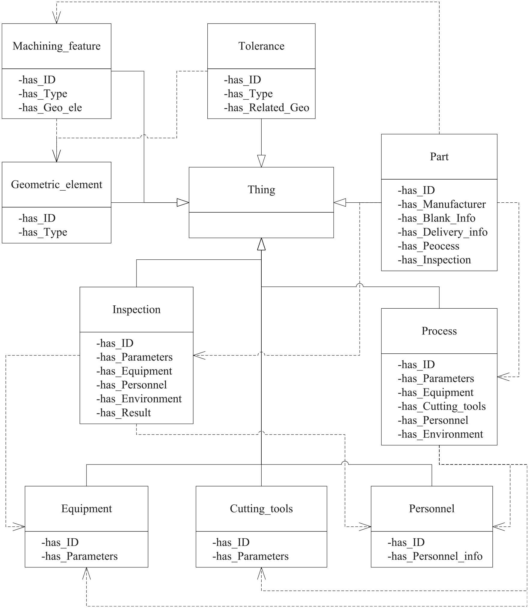
Main super classes and relationships of digital twin ontology.
The ontology established above is usable for both part manufacturers and assembly workshops. However, there still should be some differences due to differentiation in focus. The ontology and method proposed are primarily oriented to assembly workshop with modeling of manufacturers’ data, delivery data and so on, which are not the focus of attention for parts’ manufacturers.
Usage of part digital twins in assembly
For an assembly workshop, the most obvious benefit of constructing part digital twins is to have a single data source with good encapsulation and searchability for every part. With the increasing attention on quality control, assembly processes are diverted from the traditional pattern that being programmed and executed uniformly. Differences among individual parts should be valued highly to meet the requirement of high-precision and high success rate in assembly. Therefore, the modeling of part digital twins could be one of the key technologies in assembly workshop for that the uniqueness of parts can be shown comprehensively instead of being retrieved by repeated quality inspection reports. Meanwhile, the ontology-based method can provide superior expansibility for the types of information contained in a part digital twin to accommodate the new assembly method or analytical measure that may arise.
At the view of assembly workshop, the process can be divided into several stages. Figure 7 demonstrates the participation of part digital twins in assembly data flow. In the stage of quality verification in high-accuracy assembly, workshop should re-inspect the vital sections of parts involved in accordance with the designing data. Meanwhile, inspection results should be recorded to update the relevant portions in part digital twins. Next, the latest inspection data can provide support for parts distribution in consideration of selective assembly for improvement of success rate. After assembly execution, specific usage details will be added in digital twins of various parts. Assembly of key components of complex products usually involves one or several circulations of inspection and adjustment. 50 The method and amount of adjustment mainly depend on precision analysis and empirical reasoning. For precision analysis, part digital twins are excellent data carriers to provide status of parts including actual shape and surface topography, while traditional multiple data sources require a great mass of time spent on data matching and fusion to meet diverse analysis needs. However, a database can be obtained by summarizing historical operation data to act as the interface between adjustment strategy and part digital twins. For example, a series of strategies could be outputted by referencing similar treatment after comparing current condition (physical status of parts, deviations and so on) with historical ones. Further applications like knowledge base and expert system can also be applied to improve efficiency and accuracy.
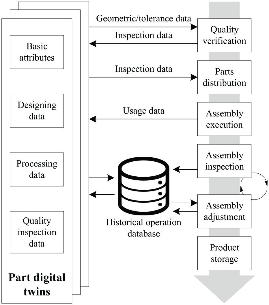
Data interaction of part digital twins in assembly.
With the expectations of how part digital twins could be effective in assembly, the advantages of using digital twins instead of traditional data sources to participate in assembly data flow are summarized as follows:
As the single data sources, part digital twins can cover all describable information related to parts, which makes it possible for other databases in assembly to record only links for individual parts instead of duplicate parts information. To some extent, it can effectively alleviate data redundancy in assembly data flow.
The management of historical data can be better realized by pre-defining a unified information structure. Complete information of the processes that a part has gone through can be found in its digital twin, which facilitates information traceability when analyzing or after delivery.
With the real-time update of part digital twins, the assembly processes of products has better monitorability and can be modularized with the change in parts status. In precision assembly that has high requirements for a certain characteristic of parts, the assembly process can be better controlled and adjusted based on the status of certain parts.
A case study
In this section, a practical application of the method of part digital twin modeling is presented. With an example of a specific part, the procedure of pretreatment and digital twin modeling can be distinctly displayed.
An example of stopping device as an assembly unit in aircraft cabin door shown in Figure 8(a) will show the analysis and modeling process. This device primarily contains four parts: base, stopping axis, locating ring and locking ring, in which the base is chosen to be the object of digital twin modeling. According to the function of stopping device, assembly requirements are determined by (1) the distance between the end face of stopping axis and the end face of base and (2) the distance between the axis of stopping axis and the bottom face of base, which can be illustrated in Figure 8(a).
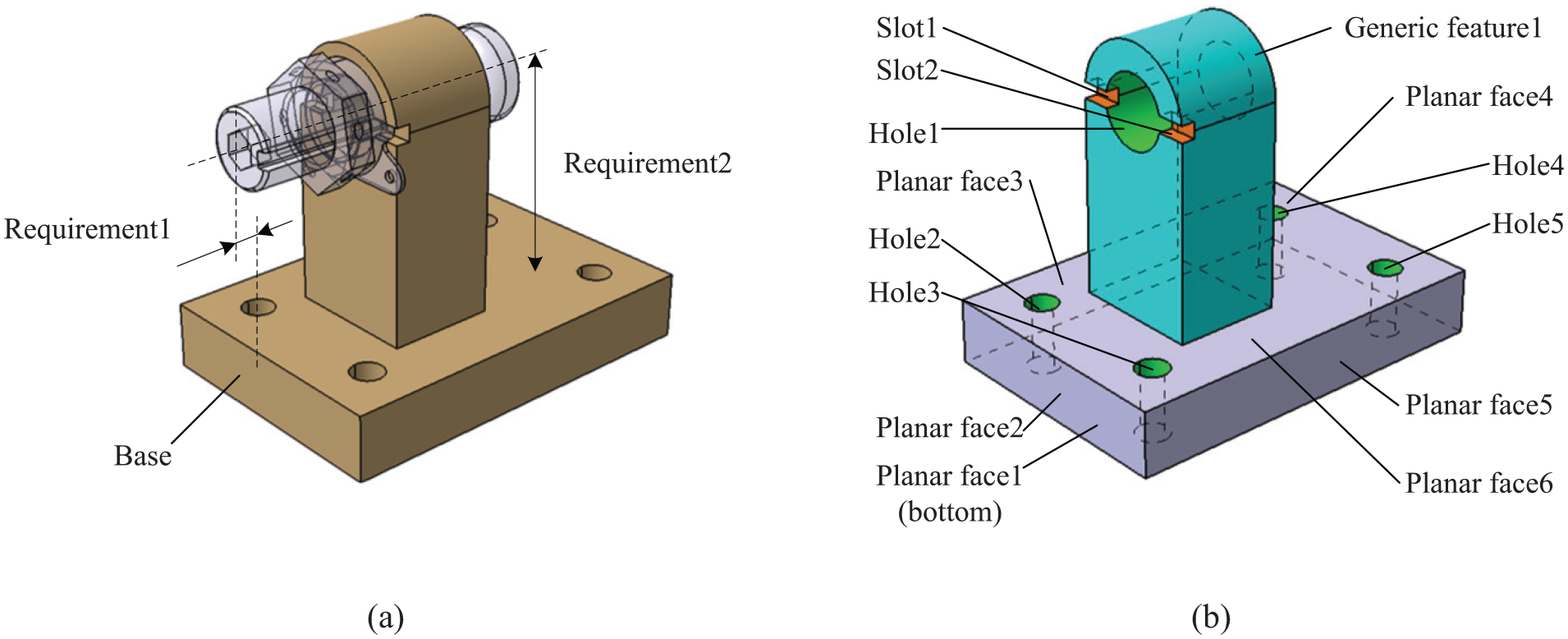
(a) Structure of stopping device and (b) machining features in base.
First of all, the result of machining features identification can be obtained as shown in Figure 8(b) by the method proposed above. Geometric elements of the base can be divided into six planar faces, five holes, two slots and one generic feature. After creating instances of machining features and geometric elements, the relationships among them are shown in Figure 9, in which the unrelated instances are hidden to guarantee the readability. With the rules of reasoning, key assembly features can be obtained to be Base-Pf2, Base-Gf1, Base-Hole1 and Base-Pf1. Meanwhile, the benchmarks of these key assembly features are inquired by the processing data and be considered as key assembly features as well. Of this part, the additional key assembly features are Base-Pf3 and Base-Pf5. Obviously, different processing technologies and location methods can result in inconsistency of benchmarks and then bring some uncertainty in obtaining key assembly features of a definite part. The key assembly features could be changeable to a certain extent depending on the specific supplier.
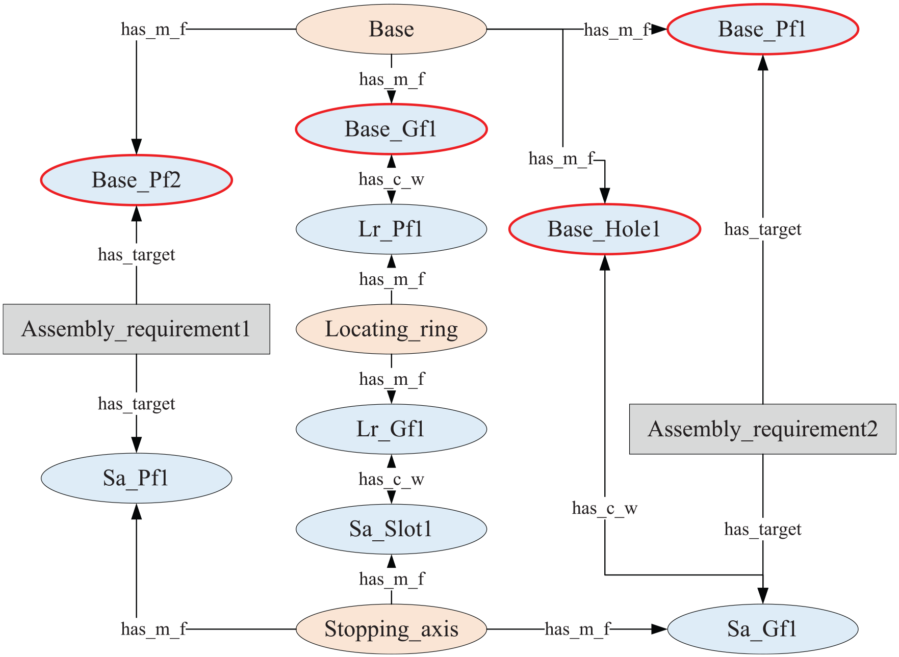
Geometric instances in reasoning key assembly features of the base.
As mentioned in the previous sections, the sources of data may have certain diversity in building digital twins of parts. For the sample part, information is obtained mainly from two aspects: MBD designing model and information systems of part supplier. On one hand, with the disseminating of MBD and CAD technology, MBD models can cover most of the information in the part designing phase including geometric shapes and tolerance. The test model generated from CATIA V5R18 with real value of geometric dimensioning and tolerancing can be re-expressed in an OWL file with an extensible markup language (XML) file as middleware, during which the machining features are identified with a component secondary developed in CATIA. In addition, the MBD models, which can contain processing data and inspecting data, have attracted a lot of research, which could be expected to unify data source. However, such data should be acquired by some other systems in this case.
On the other hand, processing and inspecting data are gathered by MES along with the progress of manufacturing under most circumstances. Meanwhile, the ERP system can provide the information related to blanks and delivery. Forms are also effective in carrying some information that has not been systematically recorded. On the stand of the assembly workshop, the processing and inspecting data of key assembly features, together with other concerning data, could be submitted in the form of XML or MS EXCEL files by the part suppliers, after which the data can also be re-expressed along with geometric dimensioning and tolerancing in OWL.
The ontology that represents the structure of part information is pre-defined by Protégé. In addition, MySQL database is used to store massive data of numerous parts under the form of OWL files. For the part with mature designing and processing, there is usually no difference among individuals in the same batch of parts about MBD designing models or processing data, which makes it possible to combine duplicate entries from one batch of parts. Meanwhile, a digital twin management prototype platform is developed to visualize the information of a single part or a batch of parts. As a management tool, the platform is also available to provide users with a channel for data interaction with the database. The part digital twin framework is shown in Figure 10.
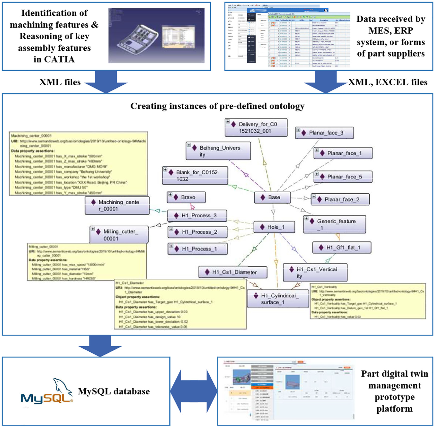
A framework of part digital twin.
Back to the demand of part suppliers and assembly workshops, with a structured information model proposed in this article by building ontology-based part digital twins, the effect of data reduction by reasoning of key assembly features remains unconfirmed. The sample part base is analyzed to compare the number of data entries with (method A) or without (method B) information screening based on key assembly features, as shown in Table 1.
Comparison of the number of main data entries.
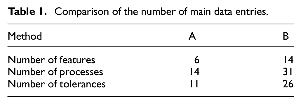
The contents in Table 1 indicate that the number of data entries is significantly reduced with information screening based on key assembly features for the base. Considering the differences among parts, the proportion of data reduction is uncertain. However, there is no doubt that the method presented can reduce cost in transmission and storage of data on the basis of ensuring that assembly analysis requirements are fulfilled.
Discussion
With the case study proposed, the methodology of part digital twin modeling provides an approach in expression of part information which can benefit both part suppliers and assembly workshops. On the position of assembly workshops, with information screening based on key assembly features, they can obtain clear and concise information sets of parts they are working with. Processing data of parts is considered to be more and more important in assembly when solving problems such as matching parts, fitting in assembly and assembly of non-rigid parts. Digital twin of part can provide a data source of accuracy and promptitude. However, the digital twin of part enables the standardized storage of information collected during processing and inspection for part suppliers. With the accumulation of historical data, knowledge could be summarized to provide recommendations when facing a new production task. In addition, the exchange of information would be transformation of sematic data among databases of part suppliers and assembly workshops if the plants participated can share one standard of information modeling method. This article proposes a standardized and precise approach to tackle the problem of creating digital twin in the cyberspace.
Moreover, uncertainty and diversity in the assembly workshops and processes have brought certain difficulties to the digital twin modeling of assembly workflow while the refactoring, monitoring and controlling of part manufacturing workshops have been extensively researched. The research in this article could be an attempt in modeling of assembly workflow of which the method of part modeling raised here can be used as the most important carrier of information for all the stakeholders. Feedback from the case assembly workshop indicates that the efficiency of part information transfer and integration has been greatly improved. With the precise definition of data entries and relationships by ontology, the digital twins of parts provide convenience for real-time analysis and historical data search during assembly.
There are still certain challenges in creating digital twins of parts with the method proposed. The first challenge is that the standards for the machining process and inspection are not comprehensive. ISO 14649, as the most widely accepted standard in regulating the description of processes, has only comprised the processes and tools for turning and milling. As for inspection, different kinds of equipment exist with different descriptions, which bring complexity and redundancy to the information model of inspection. With the improvement of the international standard system, the description of process and inspection will become more versatile and universal. In addition, the interface between digital twin management platform and original MES deployed in the assembly workshop is encouraged to be developed to promote the application of digital twin in assembly process. Digital twins of parts will provide advanced data support for simulation and analysis of assembly workflow through integration with existing information systems.
Conclusion
With the increasing requirements of information in the mechanical industry, digital twin-driven applications provide a new attempt to organize and utilize information. The digital twin model presented in this article can be used to express multi-source heterogeneous data of parts as a single data source to participate in digital assembly. Meanwhile, the digital twin can handle more complex parts with extension because of the editability of the ontology as the information template of digital twin. A case study proves the practicality of the digital twin framework and the reduction of information by reasoning key assembly features. In addition, the discussion indicates that part digital twin can benefit firms involved in product manufacturing and improve the way information is transmitted in the long run.
The modeling method of parts proposed can be the first step and also the indispensable component in the digital twin modeling of the assembly production. The future research will focus on the evaluating and modeling of assembly resources in the virtual space, including frocks, fixtures, assembly equipments and workers. Meanwhile, the method of key assembly features reasoning mentioned in this article is an attempt to deal with assembly units without intricate deviation transmission path, which should be researched as well to handle complex assembly units.
Footnotes
Declaration of conflicting interests
The author(s) declared no potential conflicts of interest with respect to the research, authorship, and/or publication of this article.
Funding
The author(s) disclosed receipt of the following financial support for the research, authorship, and/or publication of this article: This work was partially supported by the Nature Science Foundation of China (Grant Nos. 6157 2056 and 6197 2011), the Beihang University, Key Laboratory of Aeronautics Smart Manufacturing, Beijing, China. The authors are also grateful to our industrial collaborator, AVIC SAC Commercial aircraft Company, LTD., for their valuable raw data.