
Abstract
This article proposes a novel method for tolerance specification on revolving components. The revolving parts are widely used and functionally important. An exclusion approach is introduced to construct a tolerance specification method. A functional analysis tool is developed to select features to be specified and to generate their datum reference frame. A set of rules are modelled to create suitable specification schemes. The independent axiom and entropy theory are applied for further specification refinement. A software application is developed, and an RV (RV is a code of model) reducer is used as a case study. A comparison with other specification methods is undertaken.
Keywords
Introduction
Tolerancing plays an essential role in the management of the geometrical variation of a product from conceptual design to final product.1–3 With the trend towards digital manufacturing and intelligent manufacturing, 4 the related international standard is evolving to include an enriched description of both a real product and its digital twin. 5 This enrichment helps the engineers ensure a given geometrical variation of a product throughout its life cycle. On the contrary, this enrichment increases the difficulty in the development of tolerancing specification for the engineer. To this end, some software packages have been developed to assist the designer (detailed in section ‘Methodology’).
This article focuses on the tolerance design of revolving components such as shafts, rollers and so on. They are widely used in mechanical products and play an essential role in their functional performance.
Computer-aided tolerancing (CAT) 6 was introduced in the 1980s. Tolerance design 7 often includes three tasks: tolerance specification, tolerance allocation and tolerance analysis. Tolerance specification also consists of three sub-tasks 7 : (1) determination of a datum reference frame (DRF), (2) selection of the tolerance and (3) assignment of a tolerance principle. This article focuses on sub-tasks (1) and (2), as sub-task (3) is highly dependent on an individual engineer’s judgements, a process which is currently not sufficiently quantified to allow it to be captured in this way. 8
To develop a tolerance specification, researchers have previously proposed and developed methods classified as reasoning approaches (see the review in section ‘Methodology’). In this article, we propose a new approach for developing a tolerance specification, namely, one involving a principle of rule-based exclusion (RBE). The section ‘The development of RBE method’ details the framework and the section ‘Implementation and case study’ presents the implementation of the RBE method. The assessment of its performance is in ‘Implementation and case study’, which is followed by the conclusion and future work.
Methodology
Literature review
Technologically and topologically related surfaces method
Clemént et al. 9 proposed the technologically and topologically related surfaces (TTRS) method which is probably the first computer-aided tolerance specification model. The TTRS method introduced the minimum geometric datum element (MGDE) model to classify the features of a part and to apply a given set of rules. The correct application of the TTRS rules is reliant on having an experienced user making the correct judgement calls.
Rule-based reasoning methods
The rule-based methods have been developed to reduce the outcome dependence on a designer’s experience. The rules (in the form of a list of conditions) can be constructed from mathematical theories, assembly relationships and/or empirical knowledge. Rule-based methods are widely used in many fields (e.g. assembly lines, 10 design evaluation, 11 etc.).
For tolerance specification, several mathematical theories have been developed in order to build the rules or reasoning matrix. Zhang et al. 12 introduced the Polychromatic Set Theory, while Zhong et al. 13 and Qin et al. 14 developed ontology-based representation methods and Hu et al. 15 proposed a Variational Geometric Constraints Network-based method. These methods are less dependent on the users’ experience; however, these models are relatively complicated.
Other methods have been developed according to the assembly positioning constraints. Anselmetti et al. 16 proposed a positioning-table method which they have implemented in a computer-aided design (CAD) system, 17 while Cao et al. 18 applied graph theory to validation algorithms. Those methods do not, however, take into account the limitations of a measurement method in certain conditions.
Finally, there are empirical rule-based methods such as that by Armillotta 19 and Haghighi et al. 20 These methods consider both the manner of assembly and inspection, though sometimes their rules may be too rigid to allow them to be successfully applied.
Case-based reasoning method
Some case-based reasoning methods and machine learning methods 21 have been introduced. Cao et al. 22 proposed a statistical-learning-based method for datum selection. Qin et al. 23 developed an ontology-supported case-based reasoning approach. These show the possibility of creating a tolerance specification via machine learning, but currently, their successful application is limited due to the lack of sufficient data to train the algorithms.
Table 1 is a comparison of the above methods. Using this comparison, we have developed a method taking into account the following considerations: (1) the manner of assembly and inspection, (2) be ISO standard 1 compatible, (3) use a rule-based method and (4) be easy to apply.
Comparison of current tolerance specification methods.
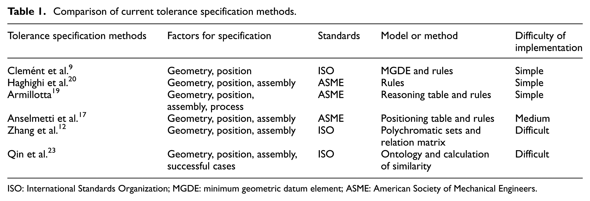
ISO: International Standards Organization; MGDE: minimum geometric datum element; ASME: American Society of Mechanical Engineers.
In the 15th Collège International pour la Recherche en Productique (CIRP) conference on CAT, further works on tolerance specification were presented, including that by Humienny and Berta, 24 Goetz et al. 25 and Patalano et al., 26 that can be classified as the reasoning approach as well.
The proposed method
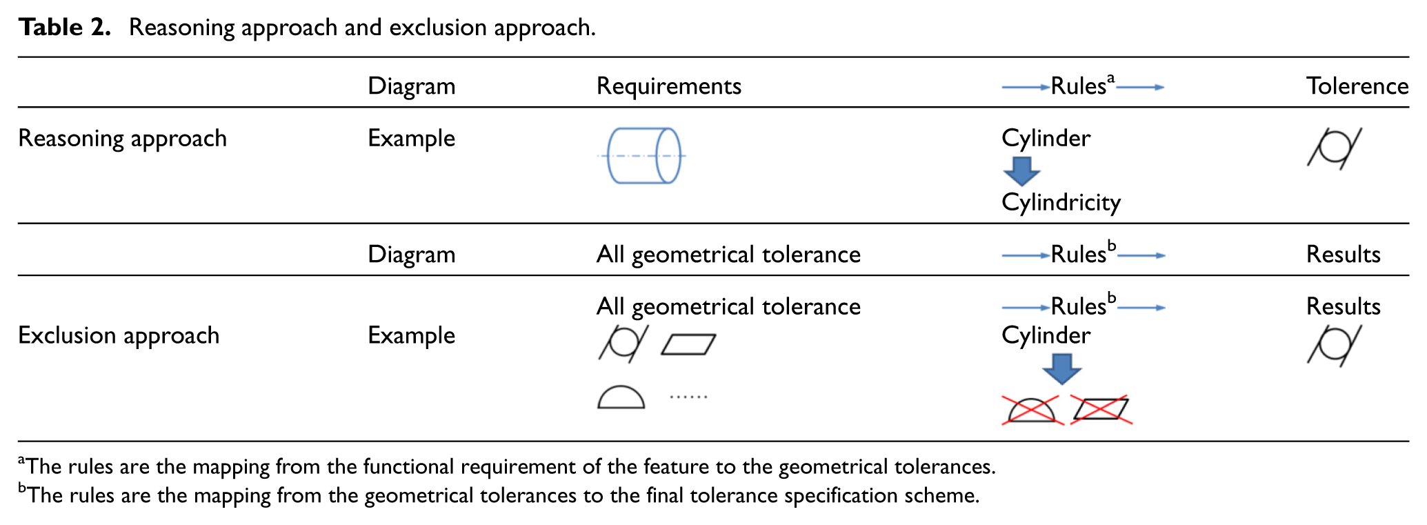
Table 2 shows diagrammatically both the reasoning approach and the exclusion approach. All the methods listed in the ‘Literature review’ section can be classified as reasoning approaches. The process taken by the reasoning approach is to develop the tolerances from the geometrical requirements of the objects specification, as shown in Table 2. The rules, tables, matrixes or cases are applied to select geometrical tolerances directly by applying the following steps (see example in Table 2): (1) an object, for example, a cylinder, is required to be toleranced; (2) the rule is followed, for example, that the cylinder is specified by its cylindricity and (3) tolerancing is applied, for example, cylindricity is selected.
Reasoning approach and exclusion approach.
 Rules
Rules
The rules are the mapping from the functional requirement of the feature to the geometrical tolerances.
The rules are the mapping from the geometrical tolerances to the final tolerance specification scheme.
An exclusion approach (see Table 2) is introduced for tolerance specification in this article. This approach has been widely applied in many fields, for example, biotechnology 27 and robotics. 28 This method uses three steps to develop the tolerance (see example in Table 2): (1) to list all possible geometrical tolerances for a feature; (2) to eliminate the tolerance items according to the rules, for example, everything except cylindricity and (3) to use the remaining tolerance items as the outcome of the tolerance specification.
In general, the exclusion approach will provide either the same number, or more, possible solutions than the reasoning approach, though it may take longer to calculate the traditional method if the number of tolerance items is large. We will develop the RBE method in the following sections with the above considerations.
The development of RBE method
The character of ‘revolving’ is utilized to model rules for datum selection. The factors of geometry, position and assembly are modelled as fixed constraints by rigid rules. Axiomatic Design (AD) theory 29 and entropy theory 30 are used for refinement. Figure 1 illustrates the flow of the RBE method with the key steps being shown in bold, these will be documented in subsections ‘Formulation of DRF’ and ‘Geometrical tolerances selection’.
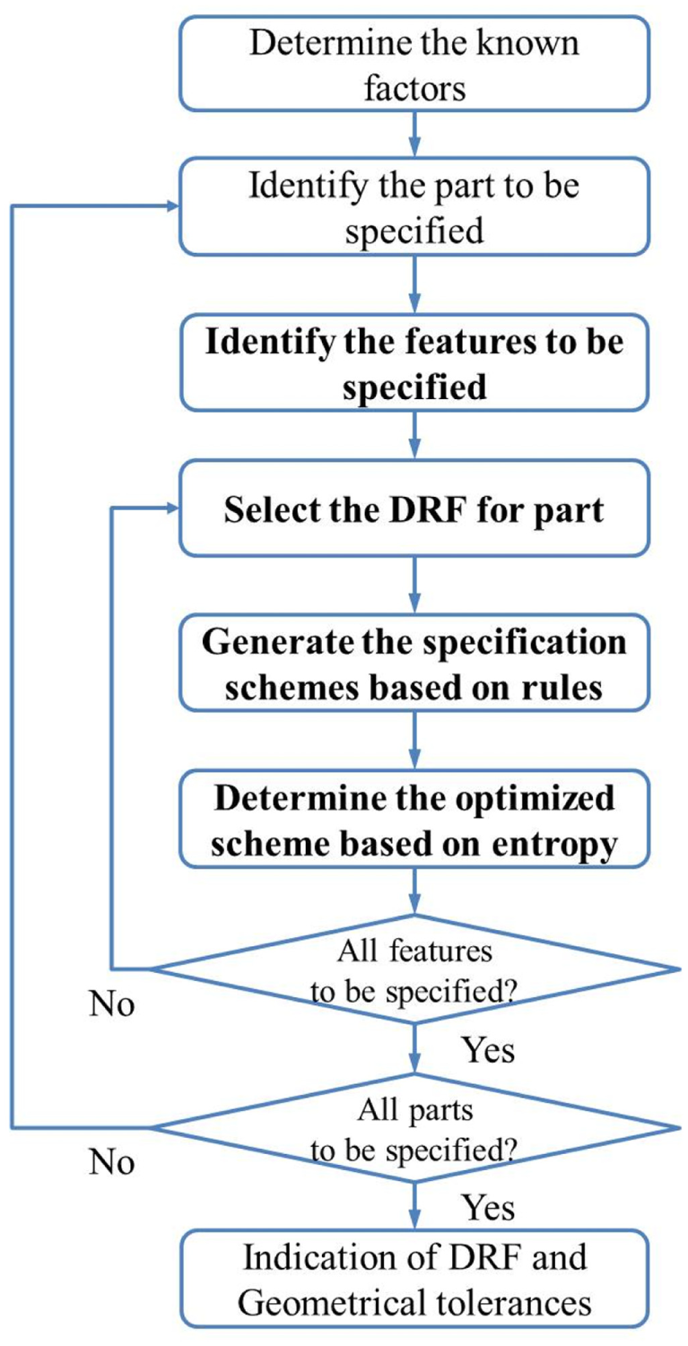
Specification flow of the RBE method.
To identify the features to be specified, information about the parts function, 17 how it is joined 19 and its assembly 23 is required. The following should be specified: (1) joined and assembly features, (2) any functional features and (3) any datum features.
Formulation of DRF
When determining the DRF, there are several significant factors 31 :
Geometrical size and accuracy grade: The largest features, and/or those having a higher accuracy grade, are often most suitable to be selected as a datum. 32
Geometrical type: Which determines the orientation of a datum. 9
Inspection method: The datum has to be suitable for measurement.
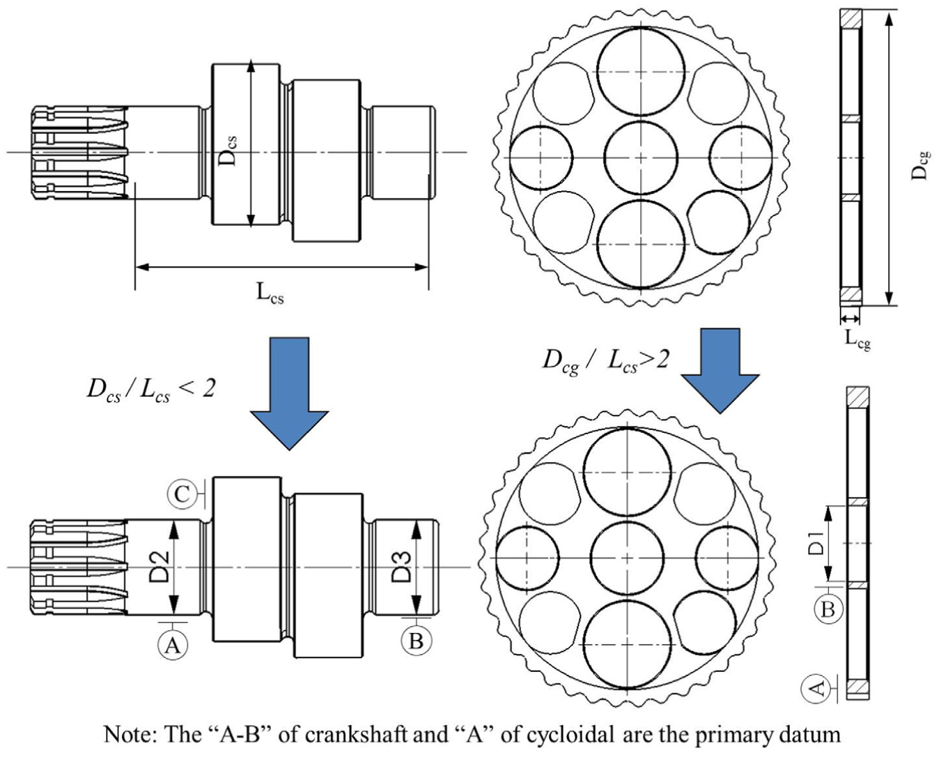
For the revolving parts, an axis datum and a plane datum should be selected via the following operations: (1) the selection of features in order to derive the central axis together with the plane perpendicular to this axis and (2) the determination of the primary datum. Rule 1 and Rule 2 are defined for operation (1) and (2), respectively.
Rule 1: datum features selection rule
A feature (i.e. revolving surfaces) is to be selected if the central axis can be derived from it. If several features satisfy this condition, the primary selection is the feature(s) related to supporting parts (such as bearing and support frame).
To derive the planar datum, a plane feature is selected which does not have an assembly relationship with another part. If several features satisfy this condition, then the feature with the largest area is selected.
Rule 2: primary datum selection rule
The plane datum feature is selected as a primary datum, if
Definition 1
The relative size of a datum feature (note as rd) is the ratio of the length of the revolving feature in the axial direction and length of the plane in the radial direction.
The factor
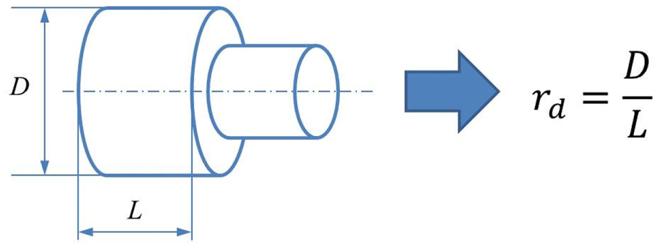
An illustration of
Geometrical tolerances selection
Figure 3 shows the process of tolerance selection. Note that the process may terminate at any step when a unique tolerance scheme is obtained.
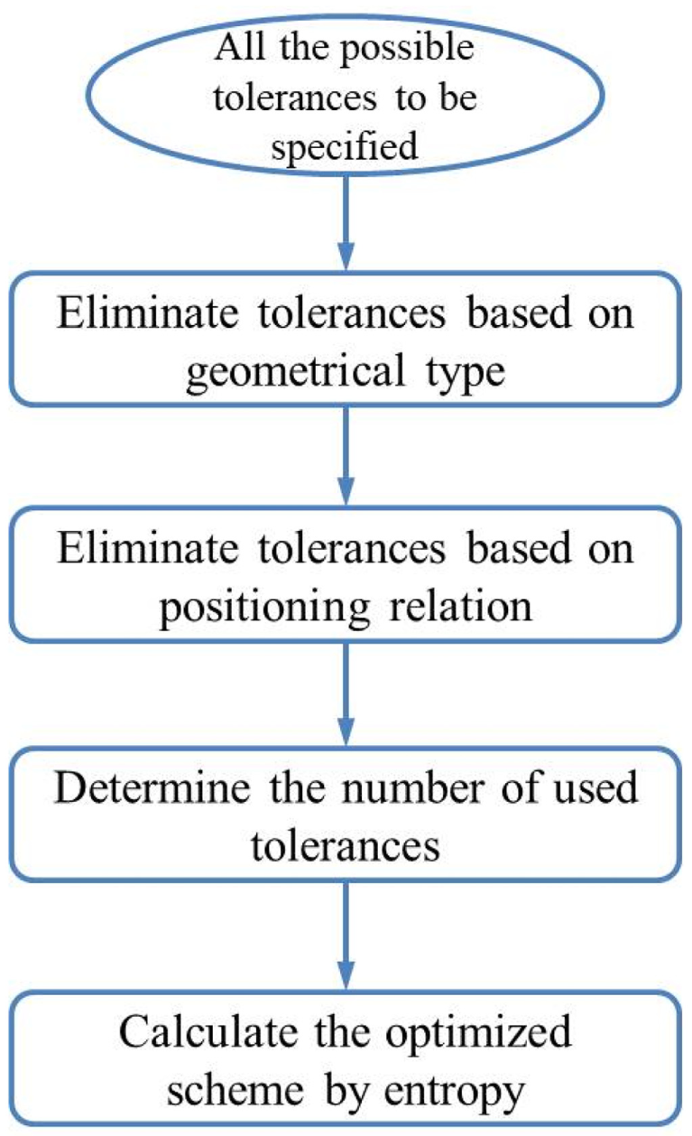
The process of geometrical tolerances selection.
Initially, all possible tolerances are listed. All the geometrical tolerances 33 and the design parameters (DPs), along with the symbols used to denote them are listed in Table 3.
DPs, symbol and requirement of a datum of each geometrical tolerance.
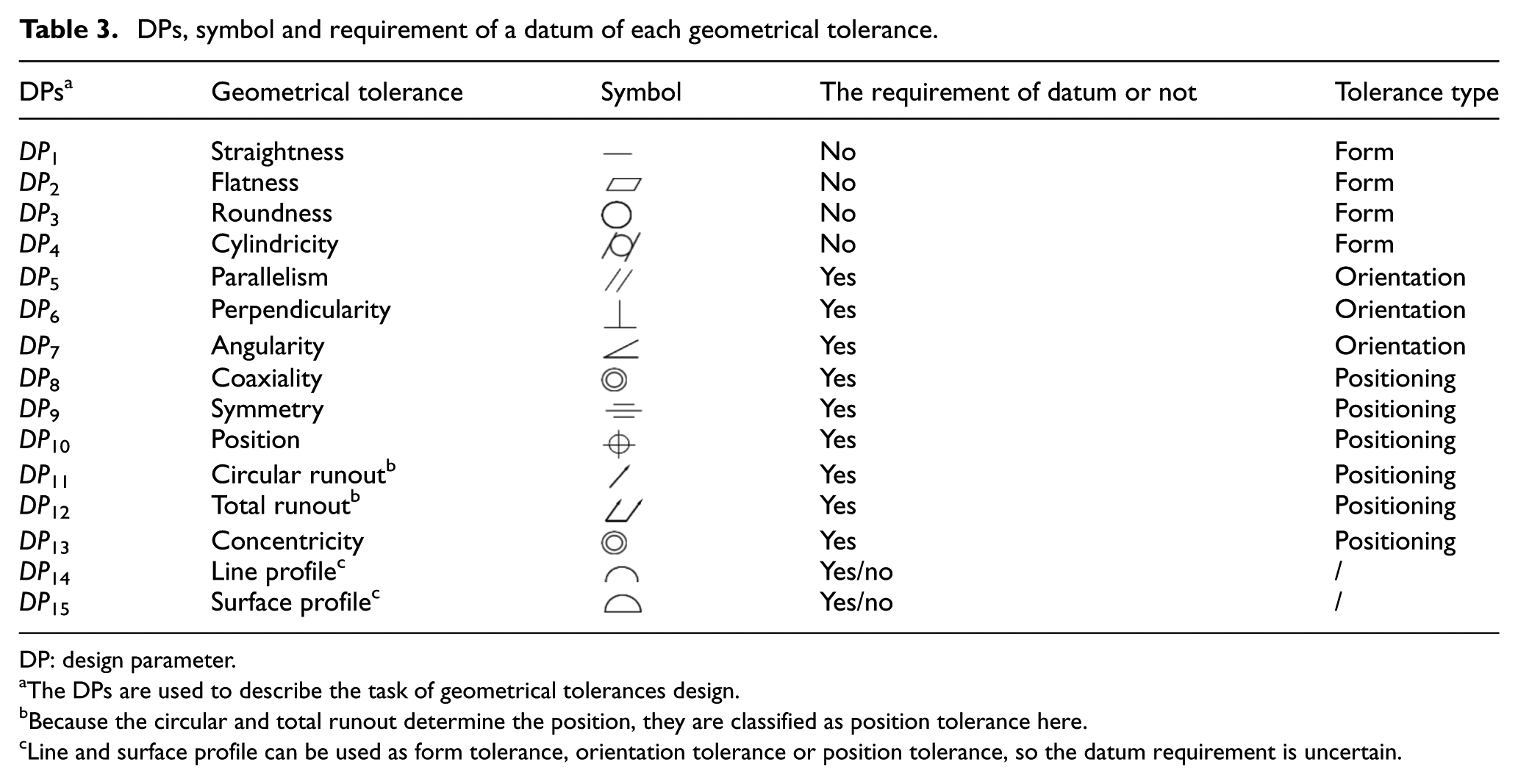
DP: design parameter.
The DPs are used to describe the task of geometrical tolerances design.
Because the circular and total runout determine the position, they are classified as position tolerance here.
Line and surface profile can be used as form tolerance, orientation tolerance or position tolerance, so the datum requirement is uncertain.
The geometrical type of a feature is an essential characteristic in the selection of tolerancing. Thus, the geometrical type rule is introduced.
Rule 3: geometrical type rule
A geometrical tolerance must satisfy the requirements of the feature’s geometrical types; otherwise, it will be removed from candidate tolerances.
The geometrical type of a feature can sometimes determine the geometrical tolerances. The geometrical tolerance for a free-form surface is unique (i.e.  ), while the geometrical tolerance for a plane is variable. Appendix Table 7 lists the possible geometric tolerances according to the geometrical type
9
and their definitions.
1
), while the geometrical tolerance for a plane is variable. Appendix Table 7 lists the possible geometric tolerances according to the geometrical type
9
and their definitions.
1
For some features, that is, a plane and a revolving surface, there are many possible results. Rule 4 is then applied which is an exclusion operation based on the TTRS method. 9
Rule 4: positioning relationship rule
A geometrical tolerance must fulfil the requirements of the relationship between a feature and the primary datum; otherwise, it will be eliminated from candidate tolerances.
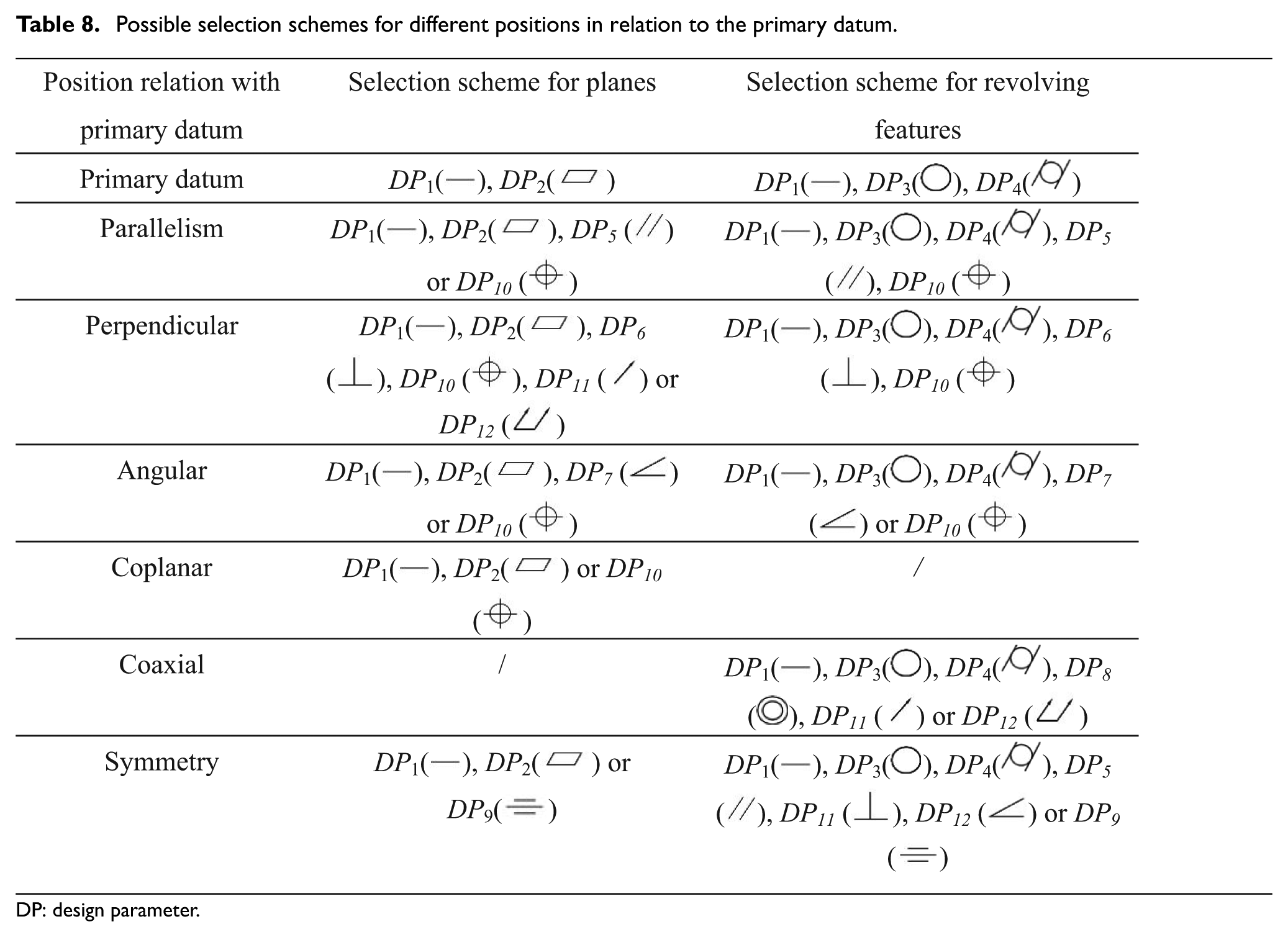
For example, if a feature is parallel to the primary datum, then DP5 (//) is employed for control of the orientation, but not DP11 (⊥) or DP12 ( ). If a feature is a primary datum, its orientation and position variation would not be specified. Appendix Table 8 illustrates different conditions and their corresponding possible geometrical tolerance.
The AD theory is introduced for further exclusion and selection. The variation requirement is treated as a functional requirement (FR), the geometrical tolerance is described as a DP 34 and a design matrix is used to model their relationships. Rules 5 and 6 are based on the independent axiom and the information axiom.
Rule 5: the independent axiom rule
The tolerances are organized according to the independent axiom rule if several candidate tolerances exist.
The independent axiom 29 requires that the design matrix should be triangular or diagonal; in other words, the number of FRs and DPs should be equal, and each FR could be satisfied by adjusting a DP individually or by several DPs orderly.
Let FRR be the variation requirement of a revolving feature. The variation of a feature can be decomposed into form variation FR1, rotation variation FR2 and translation variation FR3, according to the kinematics 35 and tolerance analysis method 36 (see Figure 4). Based on the definition of the tolerances, FR1 can be controlled by the form tolerance, FR2 by the orientation tolerance and FR3 by the position tolerance. 33
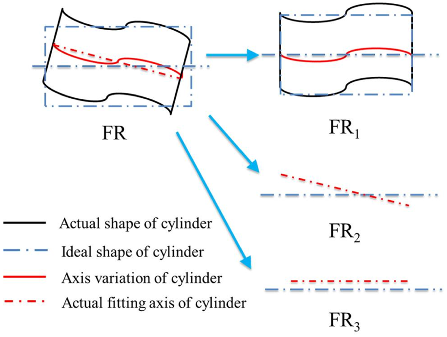
Decomposition of the variation of the revolving feature (cylinder for example).
Based on Rule 5, three geometrical tolerances are applied to a revolving feature:
DP for FR1 of FRR can be: DP1 (—), DP3 (◯) or DP4 ( );
);
DP for FR2 of FRR can be: DP5 (//), DP6 (⊥) or DP7 ();
DP for FR3 of FRR can be: DP8 ( ), DP9 (
 ), DP10 (
 ), DP11 (/) or DP12 (
 ).
).
Note 1: If a plane is coplanar to the primary datum, or a cylinder coaxial to the primary datum, FR2 will not be taken into account.
Note 2: If a plane or cylinder is used as the primary datum, FR2 and FR3 will not be considered.
If the use of Rules 3–5 does not produce a unique result, Rule 6 is employed to produce the optimized scheme based on the information entropy. 30
Rule 6: entropy rule
If there are several candidate tolerance schemes, the scheme with the least entropy is selected.
The concept of the entropy is introduced to estimate the cost and efficiency of a geometrical tolerance application. It is defined as follows:
Definition 2
The entropy, Si, is
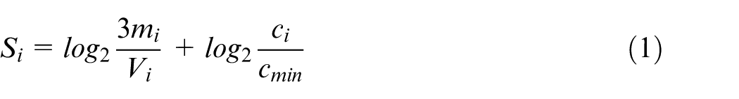
where ci (i = 1, 2, … 15) is the geometrical tolerance application, mi is the inspection precision, Vi is the maximum accepted variation and cmin is the minimal cost of all DPs.
Since the inspection precision has to be three times greater than the accepted variation, the coefficient ‘3’ is introduced.
If
The entropy of the selection scheme, S, is then
where n is the number of the geometrical tolerances and
Note: If the number of optimized schemes with minimum S is more than one, then one of them will be selected randomly for the tolerance specification.
Implementation and case study
Implementation
A software application has been developed in order to test and verify the RBE method (illustrated in Figure 5). The selection of geometrical tolerance and indication are implemented by Visual Basic for Application (VBA) in Solidworks. In the Solidworks environment, the geometrical type of feature, size and position relation can be obtained from the CAD model allowing the geometric tolerances selection to be executed. The Solidworks software package provides a DimXpert module, which has an annotation function, which is implemented by calling the API (application program interface) of DimXpert.
The tolerance specification program for feature.
The current version of API of Solidworks limits the implementation of automatic tolerancing: (1) there is a degree of difficulty in identifying features with multiple surfaces (e.g. a multiple-keys feature) and (2) it requires an initial approximation to the value.
Case study
An RV 37 (RV is a code of model) reducer mechanism is shown in Figure 6. We assume that (1) the designer has taken this RV reducer from a sketch, 38 (2) there is no previous case for reference, (3) the machining method 39 used to make the RV reducer is unknown and (4) the geometric information, the assembly relationship and the possible inspection method are known.
The primary mechanism of RV reducer.
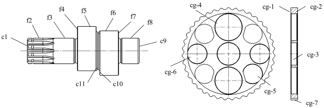
The crankshaft and cycloidal gear used in this article are shown in Figure 7, with the features f2, f3, … f8 needing to be specified as they have an assembly relationship with other features.
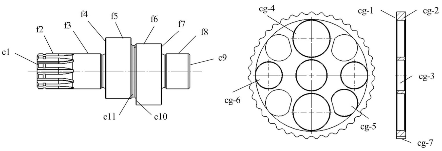
The features of the crankshaft and cycloidal gear.
In this case, the runout measurement device and coordinate measuring machine (CMM) are used for inspection. The effect of temperature is constant during inspection. 40 An estimation of all the geometrical tolerances, mi, ci (ci is a relative value) and Vi are listed in Table 4, which allows Rule 6 to be applied.
The entropy of each geometrical tolerance.
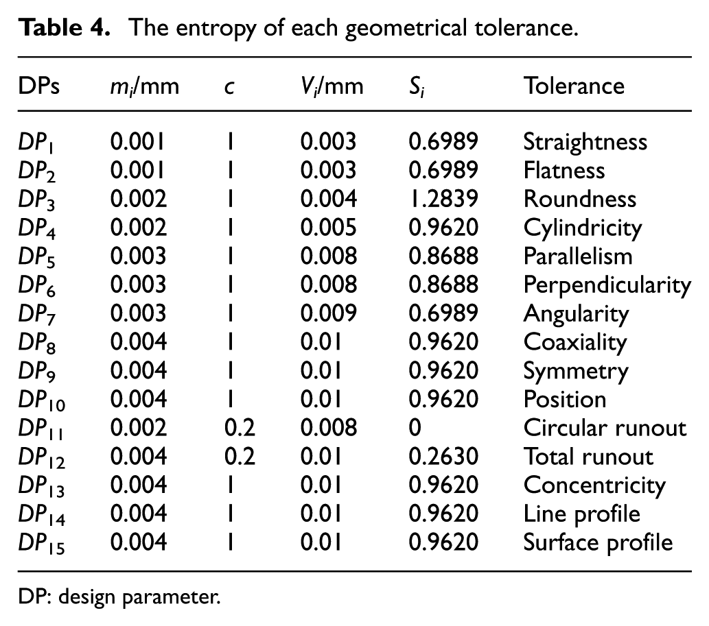
DP: design parameter.
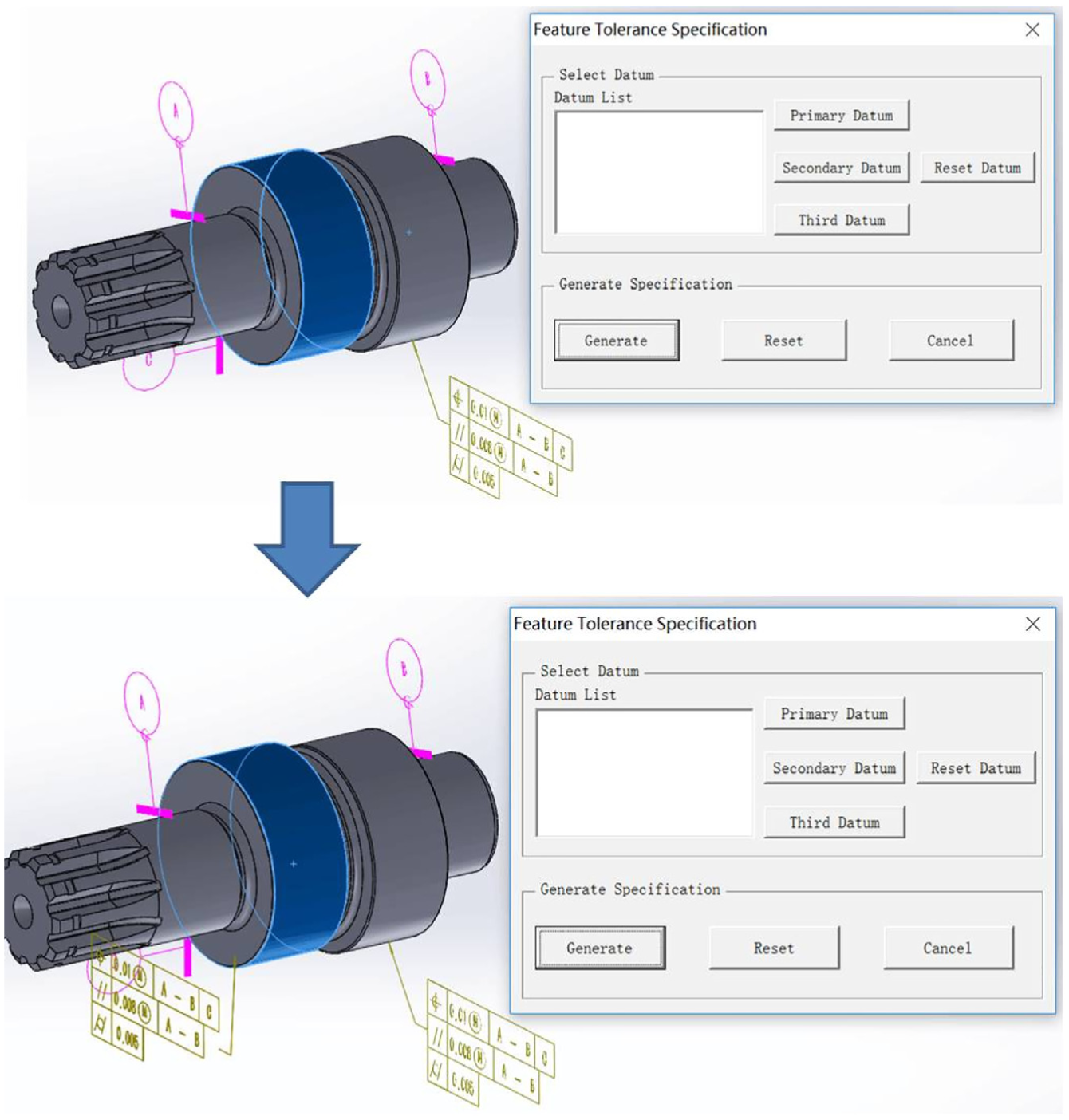
According to Rule 1, cg-3 and cg-1/cg-2 are selected as the datum features for the cycloidal gear, while f3, f8 and either f4 or f7 are selected for the crankshaft. The DRF selection process is undertaken by applying Rule 2, and the results are illustrated in Figure 8.
DRF selection process and results.
The specifications of features f2 and f7 are used as an illustration of the geometrical tolerance selection. Feature f2 is a multiple-keys feature, and according to Rule 3, DP9 () and DP11 () should be adopted. Figure 9 shows the process flow for feature f7.
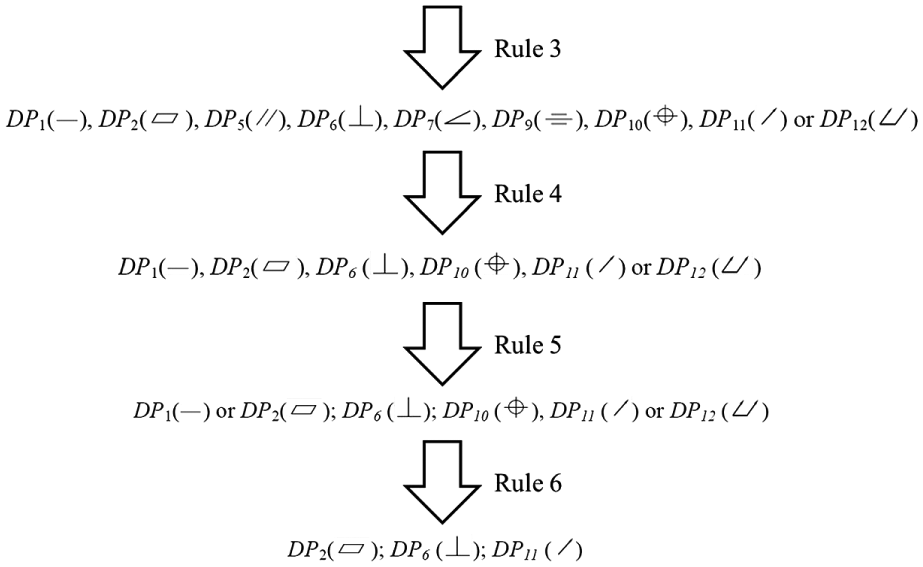
The specification flow of feature f7.
The specification results of the crankshaft and cycloidal gear are shown in Figure 10. The results of the RBE method do not conflict with the requirements of the TTRS method and strictly adhere to the ISO standard. 1 Moreover, the software application produces a specification of each feature that takes less than 2 s, which is sufficient for most applications. Therefore, this implementation addresses the common design requirements.
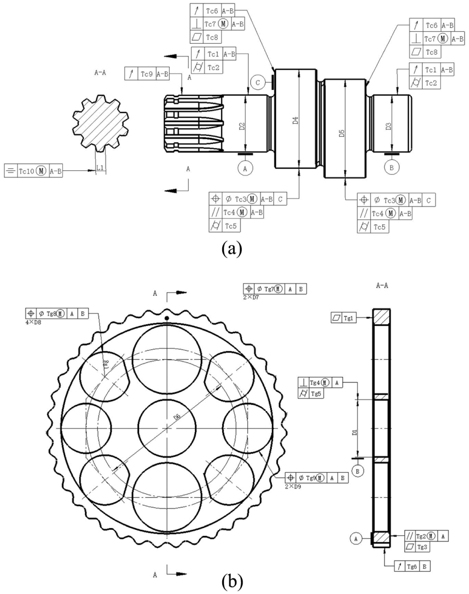
Tolerance specification result: (a) the crankshaft and (b) the cycloidal gear.
The examples of the crankshaft and cycloidal gear include a broad range of the typical types of features and positional relationships that would be expected, which indicates that this RBE method is applicable in many situations.
A comparison of the RBE method with other tolerance specification methods has been undertaken and the results are shown in Tables 5 and 6.
Specification results of the crankshaft.
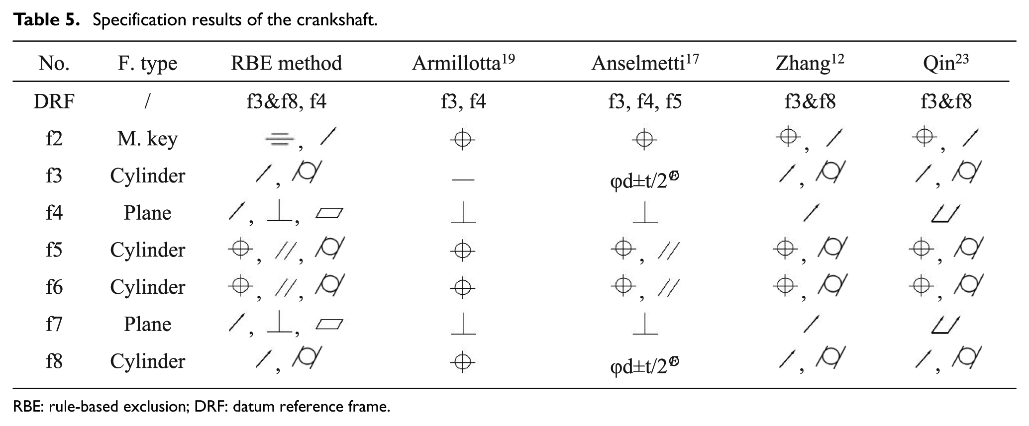
RBE: rule-based exclusion; DRF: datum reference frame.
Specification results of cycloidal gear.
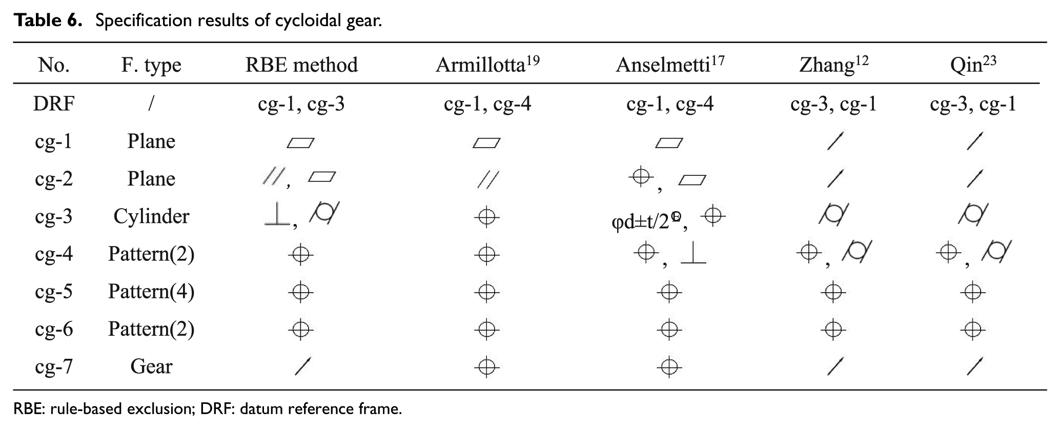
RBE: rule-based exclusion; DRF: datum reference frame.
The results selected by the RBE method are compatible with other methods in Tables 5 and 6; however, the RBE method selects a different DRF for the cycloidal gear. The RBE method selects cg-1 as a primary datum, while the methods of Zhang and Qin select cg-3. Also, the RBE method selects cg-3 as a secondary datum, while the methods of Armillotta and Anselmetti select cg-4. The different selection of geometric tolerances (due to the different DRFs) 41 is responsible for the selection of either cg-1 or cg-3.
Conclusion and future work
This article has documented the design and development of a novel method (namely, the RBE method) for tolerance specification of revolving parts. A review of the existing reasoning approaches has been undertaken. This article has introduced an exclusion approach for geometrical tolerances selection which considers both the manner of assembly and methods of inspection. An RBE method has been designed and developed, and a case study has been undertaken to illustrate its application. A software package has been developed to implement this method which shows it is relatively easy to apply. A comparison between the results of different methods has been undertaken. This has shown that the RBE method generates the specification which strictly adheres to the ISO standard, 1 and there is no conflict with the requirements of TTRS.
We aim to develop a commercially available software package in the future; however, this will require further study and verification work of the extension of the RBE method and a reliable verification method to assess the tolerance specification.
Footnotes
Appendix 1
Possible selection schemes for different positions in relation to the primary datum.
| Position relation with primary datum | Selection scheme for planes | Selection scheme for revolving features |
|---|---|---|
| Primary datum | ||
| Parallelism | ||
| Perpendicular | ||
| Angular | ||
| Coplanar | / | |
| Coaxial | / | |
| Symmetry | ||
DP: design parameter.
Declaration of conflicting interests
The author(s) declared no potential conflicts of interest with respect to the research, authorship and/or publication of this article.
Funding
The author(s) disclosed receipt of the following financial support for the research, authorship and/or publication of this article: This research was supported by the National Natural Science Foundation of China (Nos 51575484 and U1501248) and Science Fund for Creative Research Groups of the National Natural Science Foundation of China (No. 51521064). The authors would also like to acknowledge the supports by the EPSRC Future Advanced Metrology Hub (Ref. EP/P006930/1).