
Abstract
Line-of-sight rate is the key parameter that enables inertial stabilized platforms to implement guidance laws successfully for target tracking or attacking. It is always obtained by experiments. In this article, a theoretical model of the line-of-sight rate is established for the first time, starting with the gimbal motion. The strategy to acquire line-of-sight rate is based on the servo control circuit. The measurement equations for line-of-sight rate are derived using a coordinate transformation. An error model is then obtained with the help of differentiation. The error of an inertial stabilized platform prototype is measured, showing that the line-of-sight rate error can be predicted accurately. Finally, a high-precision inertial stabilized platform is successfully designed and analyzed, with the accuracy of 0.06°/s and 0.37°/s when line-of-sight rates are set to 1.5°/s and 9°/s, respectively.
Introduction
Recently, inertial stabilized platforms (ISPs) have been usually installed in unmanned air vehicles or missiles in order to track or attack targets, which is of great significance in scientific, military, and commercial applications.1–3 ISPs mainly include optical imaging system and stabilized frame. They should provide rapid and accurate rate tracking of the line-of-sight (LOS) error signals generated by the imaging sensor located in the inner gimbal.1,4 In the stabilization loop, they are utilized to keep the stability of the LOS, which is the displacement vector of the target with respect to the inertial space reference system; therefore, the carrier disturbance can be attenuated, and clear target images are obtained.5,6 In the track loop, the LOS rate, as a key signal, reflects the target motion information relative to the missile in real time. It is filtered and output for use in guidance law implementation.7,8 The typical configuration is illustrated in Figure 1. Hence, the accuracy of LOS and its rate both significantly affect the target tracking and attacking. It is necessary to model and decrease these errors to further improve system performance.
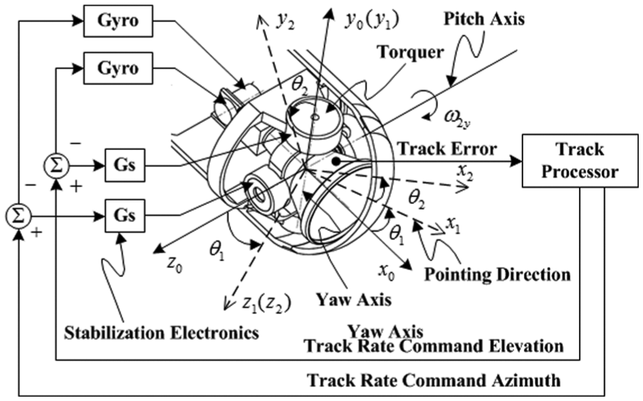
Two-axis tracker configuration.
There are currently many approaches to establishing the error model of ISPs location pointing accuracy to guarantee LOS stability, such the Debye–Huckel equation,9,10 quaternions, 5 coordinate transformation,11,12 and multi-body kinematics theory. 13 These approaches form the main basis for acquiring clear target images. Studies about LOS rate mainly focus on its estimation methods, such as the Kalman filter, 14 two-stage observer, 15 and disturbance observer-based techniques, 16 which effectively improve signal-to-noise ratio by signal processing. However, the original errors of the LOS rate cannot be analyzed and controlled. With the target position not known in real time, the LOS rate is always obtained by experiments because it cannot be mathematically calculated directly from the system sensor. Hence, it is not only an appropriate estimation method needed to improve signal quality, but it is also necessary to model the original error of LOS rate in theory so as to guarantee sufficient precision before signal processing.
In this article, a theoretical model of the LOS rate is presented for the first time. Restraining factors are calculated in detail. Error analysis and measurement for an ISP prototype is also carried out.
LOS rate modeling
Acquiring principle
To lower the system noise as much as possible, the LOS rate is acquired from the servo control circuit. Its structure for the yaw circuit is shown in Figure 2, in which the torque observer is neglected. Here,
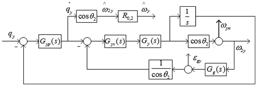
Detailed structure of the servo control system for the yaw circuit.
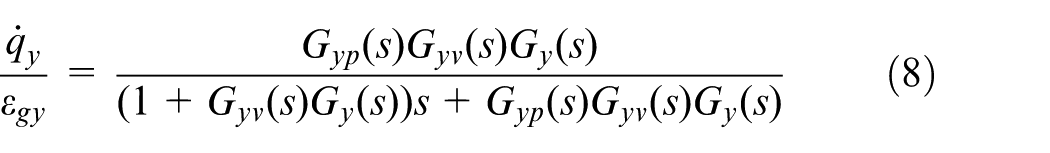
The transfer function from LOS angle to LOS rate is given by
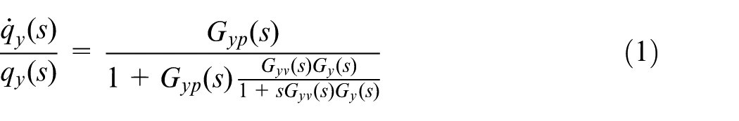
The yaw LOS rate in LOS axial coordinates is then acquired by means of a certain frequency sampling of
Error model of the LOS rate
Referring to Figure 1, three coordinate systems are used to define gimbal motion, starting with the gimbal base frame (o-x0y0z0), followed by the gimbal outer frame (o-x2y2z2), and finally the gimbal inner frame (o-x1y1z1). The oy1 and oz2 axes are coincident with yaw axis and pitch axis, respectively, while ox1 parallels the pointing direction. Furthermore,
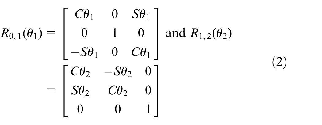
where
Let the LOS rate of yaw and pitch in the gimbal base frame be defined by
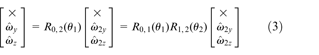
Then, the measurement equations of


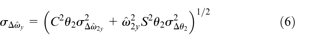
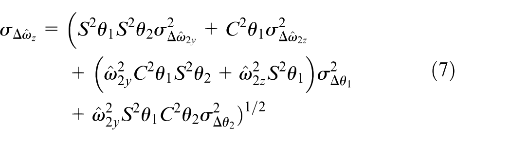
In the process of coordinate transformation, it is clear that the angle errors caused by the encoder and mechanical installation inevitably affect LOS rate accuracy. In other words, the angle errors produce a main effect on the yaw and pitch rotation angle.
Assume that LOS rate errors and rotation angles are all independent random variables, and let the standard deviation be expressed as
and
where
Error analysis and calculation
Gyroscope error
There is a direct effect of the gyro error on the LOS rate. Based on the principle of LOS rate acquisition, the transfer function from the gyro error to the LOS rate for yaw in the LOS axis coordinate system is given by
If we let the standard deviations of the gyro error for yaw and pitch be defined by

Referring to the transfer function of the gyro error, we have the following standard deviations of yaw and pitch in the gimbal coordinate system

Consequently, according to the principle of LOS rate acquisition, the standard deviations of the LOS rate for yaw and pitch in the LOS axis coordinate system are, respectively, given by

and

Encoder angle error
Assume that the same kind of encoder is adopted. Then, the standard deviations of the rotation angle for yaw and pitch caused by encoder, respectively, defined by

Mechanical installation errors
The axis rotation is always non-ideal in the process of mechanical design and assemblies; hence, mechanical installation errors are inevitable for both yaw and pitch axes. Let the standard deviations of yaw and pitch be defined by
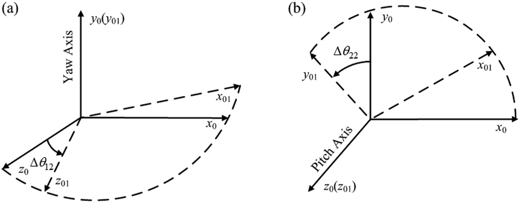
Influence of angular position on axis error: (a) mechanical installation error of pitch and LOS axes and (b) mechanical installation error of yaw and LOS axes.
Angular errors in the yaw axis mainly consist of five components, as shown in Figure 4(a), where
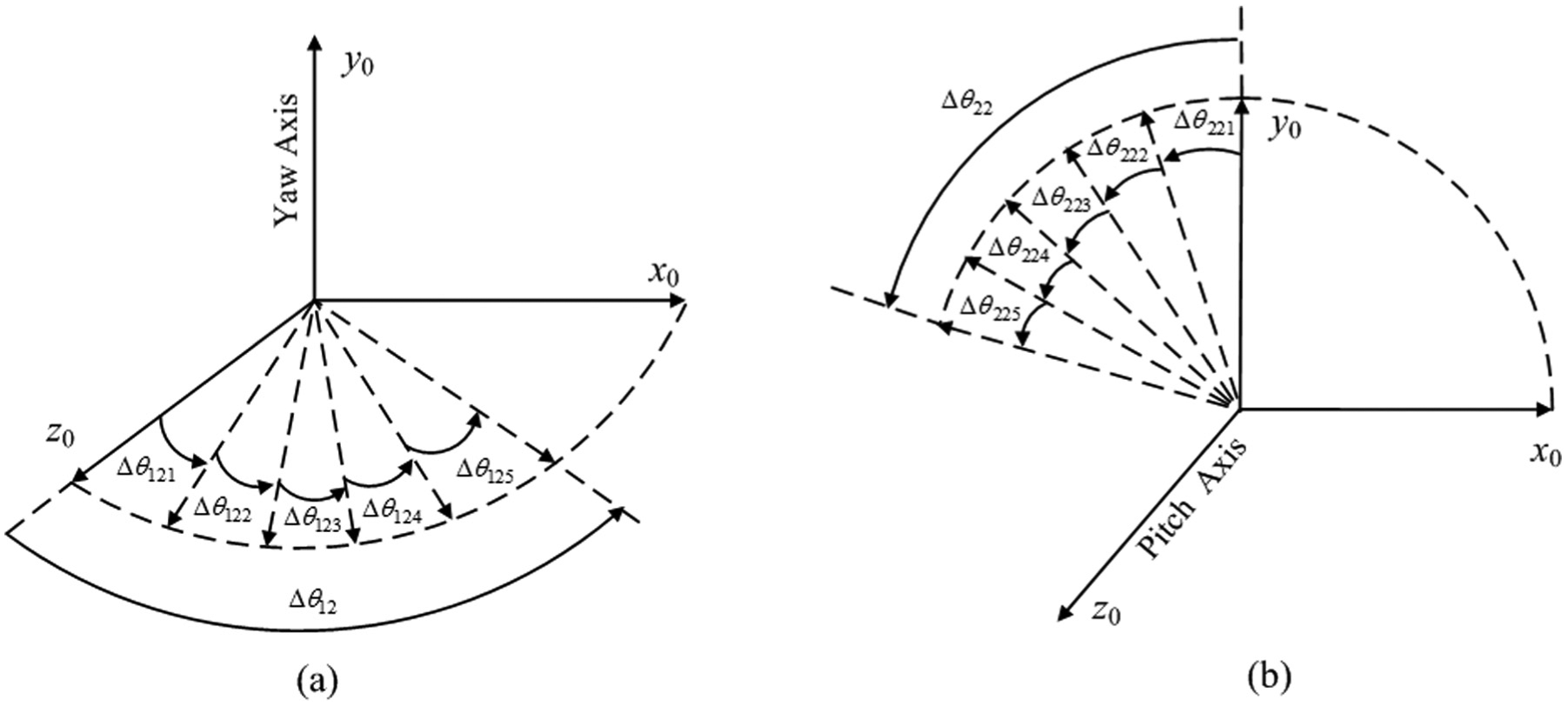
Composition of the angular error in (a) yaw and (b) pitch directions.
Therefore, the total yaw angular error defined

Assume these angular errors are all random variables and independent of each other. Then,
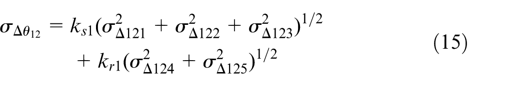
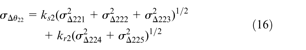
The composition of the pitch angular error is shown in Figure 4(b). Similarly, the standard deviation of the pitch angular error caused by mechanical installation can be summarized by
Experiment and results
We consider an ISP prototype with an operating range of 2000 m, a maximum LOS rate of 9°/s, and a frame angle of ±20° as an example. Furthermore, it has the characteristics of seventh-level machining precision and P4-level bearings. The mechanical installation error data used for calculation are listed in Table 1.
Error values used in the calculation and experiment.
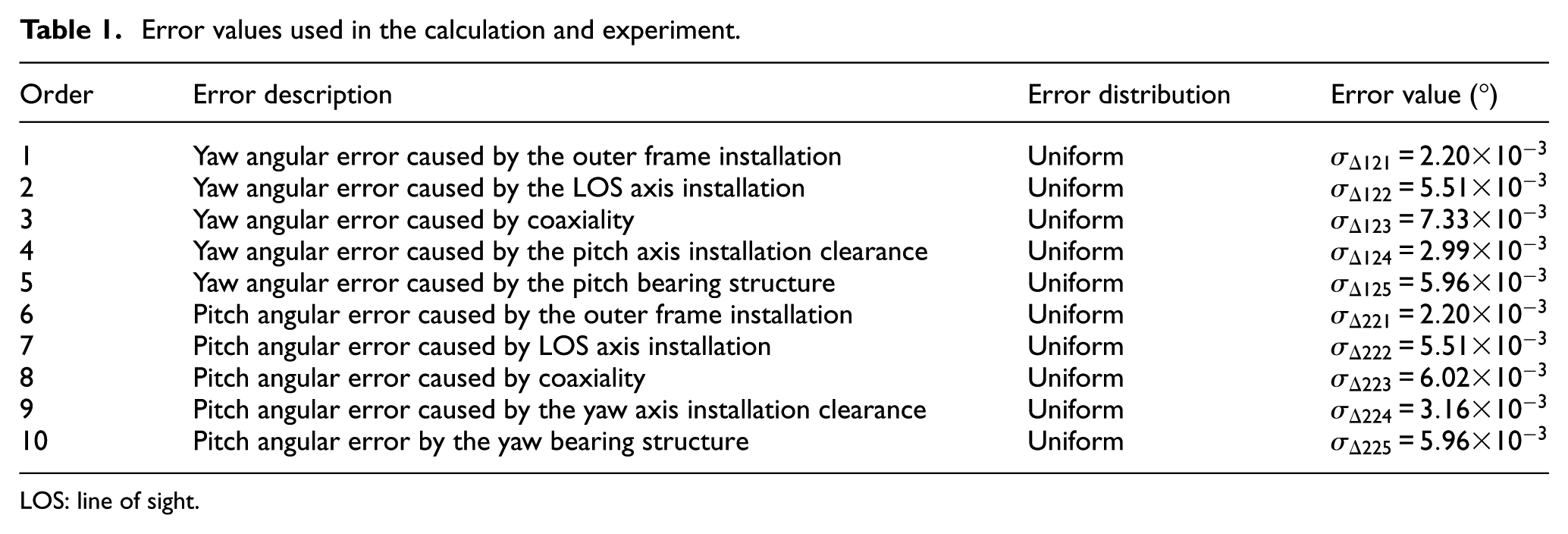
LOS: line of sight.
The experimental apparatus, shown in Figure 5, is made up of a precise five-axis turntable, an ISP prototype, an IR target simulator, and a data acquisition and control system. The ISP was installed in the roll axis, which is the inner three-axis frame of the turntable, and the IR simulator was placed in the pitch axis, which is the outer two-axis frame of the turntable. Prior to the experiment, it was necessary to align the reticule of the IR imager with that of the simulator by adjusting the angular position of the three-axis frame. In the experiment, keeping the ISP fixed, the IR target moved through the field of view of the ISP at a uniform angular velocity with a given value. Finally, the error of the LOS rate was obtained by means of data processing.
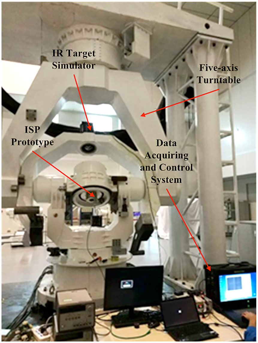
Experimental apparatus for measuring LOS rate error.
According to the system specifications and to save costs, a Micro Electro Mechanical System (MEMS) gyro with two axes (STIM210, σ = 0.067°/s) and magnetic encoder (σ = 0.05°) were adopted for the first generation prototype.Figure 6 shows the calculation errors between simulation and measurement results, with a maximum error of 6.5%. Therefore, the LOS rate model has enough accuracy for engineering design.
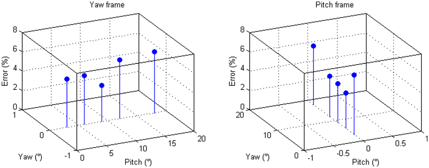
The calculation errors between simulation and measurement results.
Using the LOS rate model, a new ISP is designed and analyzed. The major technical indexes about LOS rate are that the precision is superior to 0.1°/s and 0.4°/s, when the LOS rate is set to 1.5°/s and 9°/s, respectively. After detailed calculation, the seventh-level machining precision and P4-level bearings are adopted, and a flexible gyro (σ = 0.033°/s) and 16-bit optical-electricity encoder (σ = 0.005°) are adopted based on a comprehensive consideration of the manufacturing, device cost, and practicality.
Figure 7 shows the calculation results at different LOS rates and frame angles for yaw and pitch. We can see that the LOS rate errors tend to increase as the LOS rate or frame angle increases. Furthermore, greater LOS rates lead to a larger error curve slope. Additionally, as the LOS rate and frame angle increase, the slope of the error curve becomes smaller than that of lower precision sensors. Finally, when the LOS rates are set to 1.5°/s and 9°/s with the maximum frame angle of 20°, the yaw and pitch LOS rate errors at the three sigma level are below 0.06°/s and 0.37°/s, respectively. As a result, the design specifications are satisfied in the whole design frequencies.
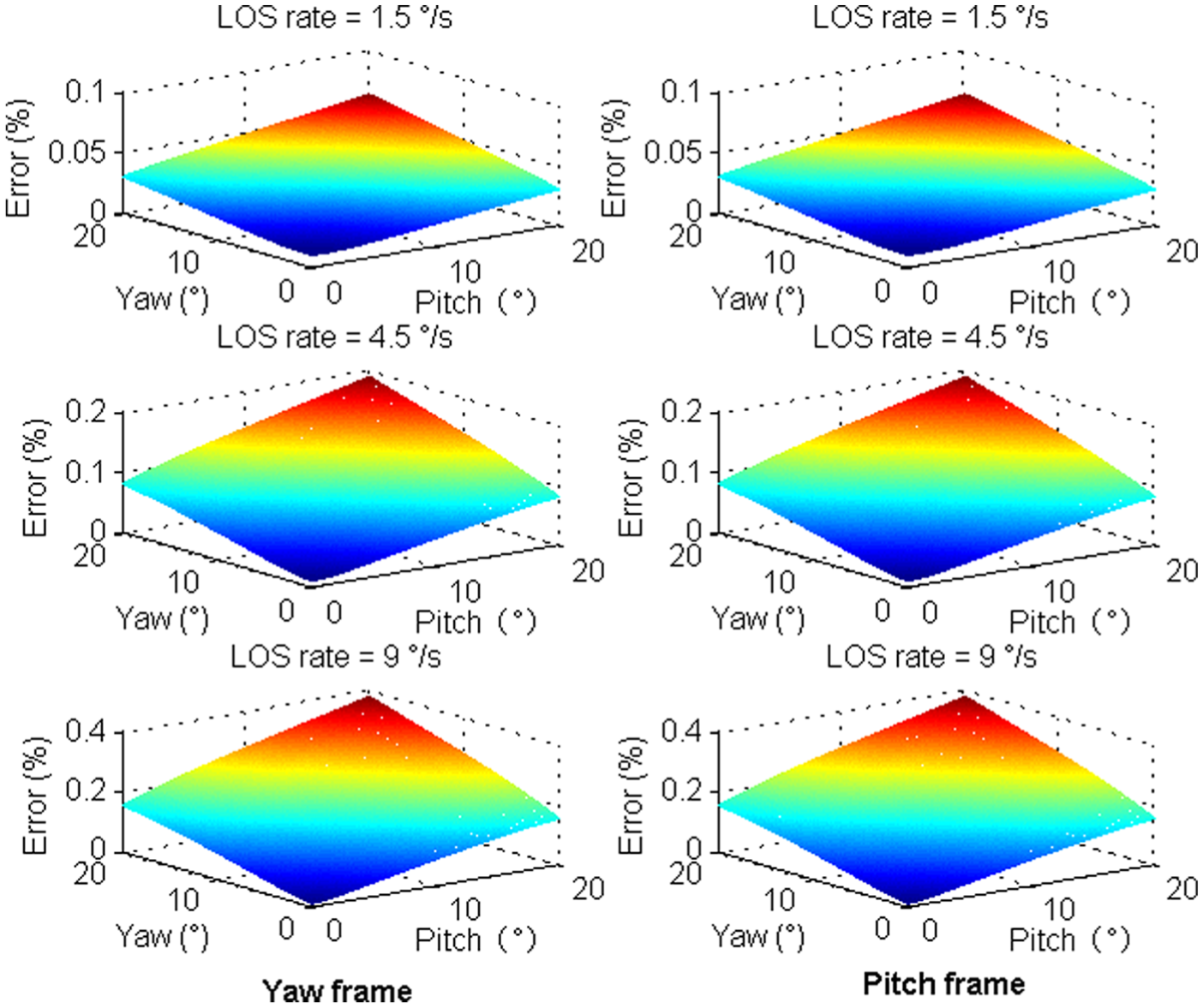
Calculation results at different LOS rates and frame angles for yaw and pitch.
Conclusion
The LOS rate is the major parameter that enables the ISP to autonomously track or attack a target. Starting with the characteristics of the system structure, a theoretical model of the LOS rate is presented in this article. The error analysis and measurement for an ISP prototype was carried out with the maximum error of 6.5%. As the LOS rate or frame angle increases, the errors also tend to increase. Furthermore, greater LOS rates lead to larger error curve slope. A high-precision ISP is designed and analyzed using the LOS rate model, with the accuracy of 0.06°/s and 0.37°/s when LOS rates are set to 1.5°/s and 9°/s, respectively. The LOS rate model has enough accuracy for engineering design.
Footnotes
Declaration of conflicting interests
The author(s) declared no potential conflicts of interest with respect to the research, authorship, and/or publication of this article.
Funding
The author(s) disclosed receipt of the following financial support for the research, authorship, and/or publication of this article: This work was supported by the National Natural Science Foundation of China (Grant No. 11372309 and 61304017) and Stage III of the Knowledge Innovation Program of the Chinese Academy of Sciences (Grant No. YYYJ-1122).