
Abstract
In this study, different methods of cutting fluid application are used in turning of a difficult-to-machine steel (SAE EV-8). Initially, a semisynthetic cutting fluid was applied using a conventional method (i.e. overhead flood cooling), minimum quantity of cutting fluid, and pulverization. A lubricant of vegetable oil (minimum quantity of lubricant) was also applied using the minimum quantity method. Thereafter, a cutting fluid jet under high pressure (3.0 MPa) was singly applied in the following regions: chip–tool interface, top surface of the chip (between workpiece and chip) and tool–workpiece contact. Moreover, two other methods were used: an interflow between conventional application and chip–tool interface jet (combined method) and, finally, three jets simultaneously applied. In order to carry out these tests, it was necessary to set up a high-pressure system using a piston pump for generating a cutting fluid jet, a venturi for fluid application (minimum quantity of cutting fluid and minimum quantity of lubricant) and a nozzle for cutting fluid pulverization. The output variables analyzed included tool life, surface roughness, cutting tool temperature, cutting force, chip form, chip compression rate and machined specimen microstructure. Among the results, it can be observed that the tool life increases and the cutting force decreases with the application of cutting fluid jet, mainly when it is directed to the chip–tool interface. Excluding the methods involving jet fluid, the conventional method seems to be more efficient than other methods of low pressure, such as minimum quantity of volume and pulverization, when considering just the cutting tool wear.
Introduction
In machining, a major portion of the energy is consumed in the formation and removal of chips. The greater the energy consumption, the greater the temperatures and the frictional forces at the tool–chip interface and, consequently, the higher the tool wear. Metal machining processes can have longer tool life and improved surface finishing if thermal and frictional conditions at the tool–chip interface are controlled. Lubrication and heat removal from the cutting zone is a natural way to keep the cutting tool wear under control, so cutting fluids have been traditionally used. An important role of these fluids is to reduce the thermal gradients in the cutting zone, since it is well established that the heat generated influences both the wear rate and the mechanical properties of the cutting tool material.
Flood cooling is not effective in terms of lowering cutting temperature because the coolant does not readily access the tool–workpiece and tool–chip interfaces that are under seizure condition. The tool–chip interface is usually divided into two regions. At any instant during the cutting process, a part of the interface is exposed to full seizure (sticking region), while the remaining part undergoes interfacial sliding. If there is seizure at the rake face of a tool, internal friction and heat will be generated because the workpiece material is subjected to shear stresses.1,2
A flood of fluid directed over the back of the chip (conventional method) is the most common way of applying the coolant onto the cutting zone. In this case, the heat generated during the contact of the tool with the workpiece is extracted via the chip. However, at higher cutting speeds, it has been proved that the cutting fluids lose their effectiveness as a coolant. This can be attributed to the greater rate of heat generation, the inability of the cutting fluid to reach the regions to be cooled and the tendency of the faster moving chips to carry the cutting fluid away from the cutting zone. 3
The machining of the so-called hard-to-machine materials, such as nickel and titanium alloys, is difficult due to their considerable heat resistance, high reactivity with carbide tools, low thermal conductivity and, especially, work hardening. Usually, these materials cannot be cut effectively without cooling, even though dry cutting is becoming increasingly widespread. However, dry machining is a popular alternative to the conventional method (i.e. overhead flood cooling), but problems with chip formation and temperature increase in the workpiece cause a reduction in productivity and quality. These problems are especially found in machining of superalloys and titanium alloys widely used in the aerospace industry. 4 In addition, severe problems with dimensional accuracy due to the allocated heat in the machine tool must be considered. 5
The decrease in temperature using the conventional cooling method, compared with the temperature which occurs in dry machining, is only about 15%. 6 The steam generated around the hot surfaces of the insert and the chip effectively prevents the water from cooling the cutting zone and dissipates the heat generated. The steam acts like an insulating barrier. In spite of this, overhead cooling is frequently used in the industry. In order to achieve a 40%–45% temperature reduction, it is necessary to break the thin skin of steam with a concentrated water jet. Machining under a pressure jet from 25 to 300 MPa directed at the tool–chip interface, besides improving the cooling and chip control compared to the conventional method, the fluid jet can change the cutting process by changing the frictional conditions and, thus, the shear plane angle. 6 Observed results show that the temperatures produced in the cutting zone are close when using this range of pressure, a pressure limit value being clear.7–9 In fact, when machining Inconel 718 under high-pressure fluid toward the tool–chip interface, the increase in pressure between 11 and 20.3 MPa did not necessarily lead to the increase in tool life for tested cutting speeds of 30, 40 and 60 m/min, with a feed rate of 0.1 and 0.2 mm/rev. 10 For a lower cutting speed, of 30 m/min, the conventional method produced a tool life similar to the fluid jets.
The use of ceramic tool, instead of coated carbide tool, presented highlighted notch wear mechanism, which can be attributed to fluid jet impingement erosion accelerated by increasing coolant pressure due to higher stagnation pressure. 11 A similar wear mechanism was found in the Inconel 901 machining with different tools in which a major tool life for a conventional application in relation to the high pressure was verified. 12
The effects of coolant flow rate on the corresponding heat transfer coefficient in overhead jet cooling and flank jet cooling were studied, and the results indicate that the heat transfer coefficient grows with an increasing flow rate.13,14 However, a small percentage increase in the heat transfer coefficient requires a large percentage increase in the flow rate. In overhead jet cooling, to increase the value of the heat transfer coefficient by n times, the jet flow rate has to be increased by about n1/0.7 times. In flank jet cooling, to increase the value of the heat transfer coefficient by n times, the jet flow rate has to be increased by about n 2 times.
In experiments, it is shown that the chip up-curl radius decreases with the hydraulic power (P = p × q) of fluid jet. 15 But it was observed that for the same hydraulic power, the radius also varies when the pressure and the flow rate are modified; thus, the combination between increasing flow rates and decreasing pressures generates chips with smaller curl radius. As a result, it was found that the jet momentum (F = v × q ×ρ), which is proportional to the jet speed (v), flow rate (q) and density (ρ), relates better the fluid jet characteristics to the chip curl radius, so that the increase in the values of jet momentum produces lower radii.
Pigott and Colwell, 16 in their pioneer work, used a pressure of 2.75 MPa directed to the flank face, between the tool and the workpiece, obtaining an increase in the tool life from seven to eight times in relation to the conventional application. The fluid applied in this position is as effective in the cooling as in the friction reduction, preventing the increase in the contact between the tool and the workpiece.17,18 Recently, researchers19,20 applied cutting fluid in this direction and obtained better results than at the chip–tool interface; although the jet pressure has been of 1.2 MPa, the lowest found in the literature on high-pressure fluid may be insufficient for creating an effective fluid wedge. Sharman et al. 21 used high fluid pressures directed to the rake face, the flank face and both positions together, in turning of Inconel 718 under finishing conditions (depth of cut = 0.25 mm, feed rate = 0.35 mm/rev). The cutting speed of 40 m/min was used with fluid pressures of 7, 15, 30 and 45 MPa applied in the three positions. The trials showed no significant improvement in tool life over those results obtained with conventional cooling, leading the authors to conclude that the temperature generated by finishing conditions was not sufficiently high for receiving the benefit of the greatest cooling produced by the high-pressure jet. In addition, the results showed that the high-pressure jet has no beneficial or detrimental effect on the level of workpiece microstructural deformation or surface roughness, in contrast with the general literature about this subject.
The cutting fluid applied on the rake face can increase the tool life by 3–4 times as compared with the conventional application. It was concluded after grooving operations studied in Ti6Al4V using high-pressure coolant, between 10 and 30 MPa, on the rake face and the flank face of the tool. 22 However, the workpiece surface may be adversely affected by the chip flow. By applying the cutting fluid on the flank face, the tool life increases by 1.5–2 times relative to conventional application, and no damage to the workpiece surface was observed. When both applications were conducted at the same time, the tool life did not increase.
Several studies point out that the machining force generally decreases with increasing coolant pressure, suggesting that a higher pressure coolant jet is able to penetrate the cutting interface, thus providing more efficient cooling and lubrication.7,8,23 The fluid wedge created by the coolant at the tool–chip interface tends to reduce the tool–chip contact length and the coefficient of friction, consequently lowering component forces. Nevertheless, in these studies, it was possible to realize that there is a value range above which the increase in the pressure implies neither lowest machining force nor longest tool life. Similar results were found by Courbon et al. 9 and Kramar et al. 24
Even if the fluid application method under high pressure is more efficient than the conventional method, the increasing rigor of environmental legislation has motivated the usage of minimum quantity of lubricant (MQL). This technique, also known as near-dry machining, is made by means of oil drop atomization, usually from vegetable origin, with the purpose of lubricating the cutting zone. Indeed, problems associated with the low capacity of heat removal by oil, the difficulty of its tiny, light drops reaching the hottest surface of the cutting zone and the impossibility of taking out chips from the cutting zone make this method practicable only in specific machining operations. Alternatively, larger drops than what the MQL method produces could be applied through hydraulic pulverization of the cutting fluid, without using air, with an appropriate nozzle. Nevertheless, there is no information regarding this fluid application method in the literature, in contrast to the large number of works dedicated to the performance evaluation among the MQL methods, dry machining and conventional, as well as a considerable number of other works dedicated to the cutting fluid application under high pressure at the rake face and/or flank face.
The purpose of this work took place due to the lack of information verified in the literature, in relation to the comparative performance of varied methods and directions of cutting fluid application, when machining the same material under the same cutting conditions. It is never treated in a single work. In addition, divergent results for the same jet directions of cutting fluid application were also noted in the literature.
In this work, different methods of cutting fluid application, both low and high pressure, are used in turning of a difficult-to-machine steel. The used material is SAE EV-8 steel, whose main characteristics are the presence of chromium carbide in its structure and low thermal conductivity. It is important to highlight that the machinability of this material is not found in the literature. Among the methods is included the jet under high pressure, around 3.0 MPa, just considered because its value is close to that used in the pioneering work by Pigott and Colwell. 16 The methods utilized were conventional by flood from the machine tool, minimum quantity of cutting fluid (MQCF), pulverization and MQL using an oil designed for this technique. In these methods, the position of fluid application was performed on the back of the chip, as it is traditionally practiced in turning. Next, the method by fluid jet under high pressure was directed toward each one of the following positions: at the chip–tool interface, at the contact between the workpiece and tool, and on the top surface of the chip. In addition, the simultaneous application of these three jets was done providing another high-pressure method. Finally, a combination of the jet at the chip–tool interface and the conventional method was introduced. The output parameters analyzed for each type of application included tool life, surface roughness, cutting force, cutting tool temperature and morphology of chips.
Materials and experimental procedures
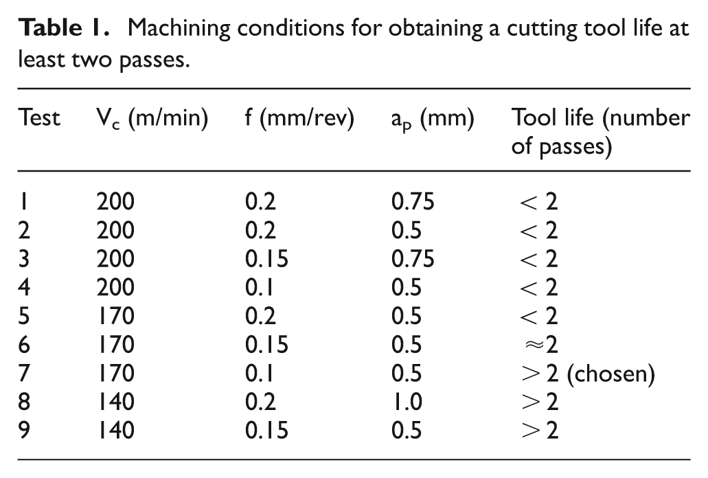
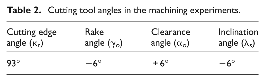
The machining trials were carried out using a conventional lathe with 7.5 kW of power equipped with a frequency inverter to keep the cutting speed constant when the workpiece diameter is reduced. The cutting tool used was a coated cemented carbide (TiCN, Al2O3 and TiN) of triangular geometry, with a flat rake face without a chip breaker, ISO designation TNMA 160408. In the fluid application methods, the machining conditions were the same: depth of cut (ap) = 0.5 mm, cutting speed (Vc) = 170 m/min and feed rate (f) = 0.1 mm/rev. These values were found after preliminary tests and corresponded to a tool life longer than two passes for dry machining, which is the worst condition, allowing a progressive evaluation of cutting tool wear, which was not possible in more severe machining conditions. This condition was selected among the values shown in Table 1. The cutting tool clamped on the toolholder provided the angles presented in Table 2.
Machining conditions for obtaining a cutting tool life at least two passes
Cutting tool angles in the machining experiments
A first group of fluid applications was carried out by the following methods: conventional flood, MQCF, pulverization and MQL. One of the common characteristics of these methods is the low pressure necessary for fluid application. In a second group, high pressure was used in the formation of fluid jet singly directed toward the following locals: at the chip–tool interface (C/T jet); on the top surface of the chip, that is, between the workpiece and the chip (W/C jet) and at the contact between the tool and the workpiece (T/W jet) in the tool flank zone. After this the combined method was utilized, which is a fluid application composed by the conventional flood together with the W/C jet method. Finally, the simultaneous application of the three jets (W/C, C/T and T/W) was used, thus totaling nine different methods.
The cutting fluid employed in the tests was a 5% solution of semisynthetic emulsion, while that used in the MQL method was a vegetable-based lubricant specially designed for this technique. In the conventional method, the fluid was directed to the back of the chip zone and the flow rate adjusted to the same value of the applications by jet.
The schematic representation and nomenclature of each application method with their respective values of flow rate and pressure used in the experiments are presented in Figure 1
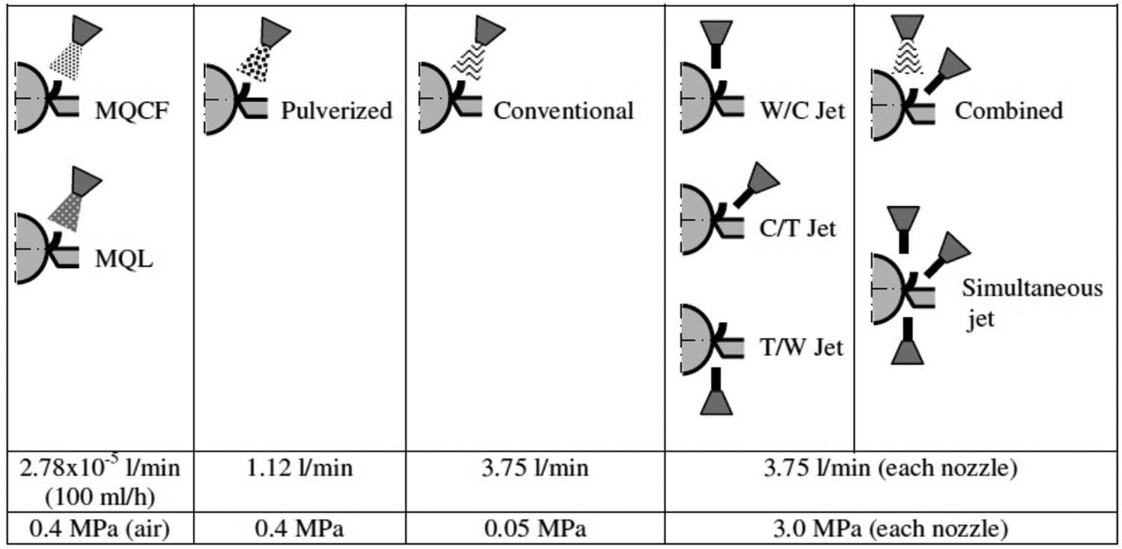
Schematic of the application methods with their respective values of flow rate and pressure.
In order to form the jet under high pressure, a piston pump, Jacto model MB-42A, was used, as well as a stainless steel nozzle with a hole of 1.0 mm in diameter set at a distance of 25 mm from the jet incidence zone. In the pulverization method, the same piston pump was used, however with an appropriated nozzle positioned at a distance of 50 mm from the tool tip. For the minimum quantity methods (MQCF and MQL), a venturi-type nozzle was also used, positioned at 50 mm from the tool tip. Inside it, the mixture of compressed air and fluid took place, and the fluid was fed by gravity. The creation of a uniform spray was possible with an air pressure of 0.4 MPa for both the cutting fluid and the vegetable oil lubricant. All of them, Venturi and nozzles for pulverization and fluid jet, are commercial items of spraying systems corresponding to the models SUV1A, 1/8 HH–KY 1.3 and H 1/8 U–SS 0003, respectively. Figure 2 illustrates the three types of nozzles that compose the fluid application methods used in the experiments.
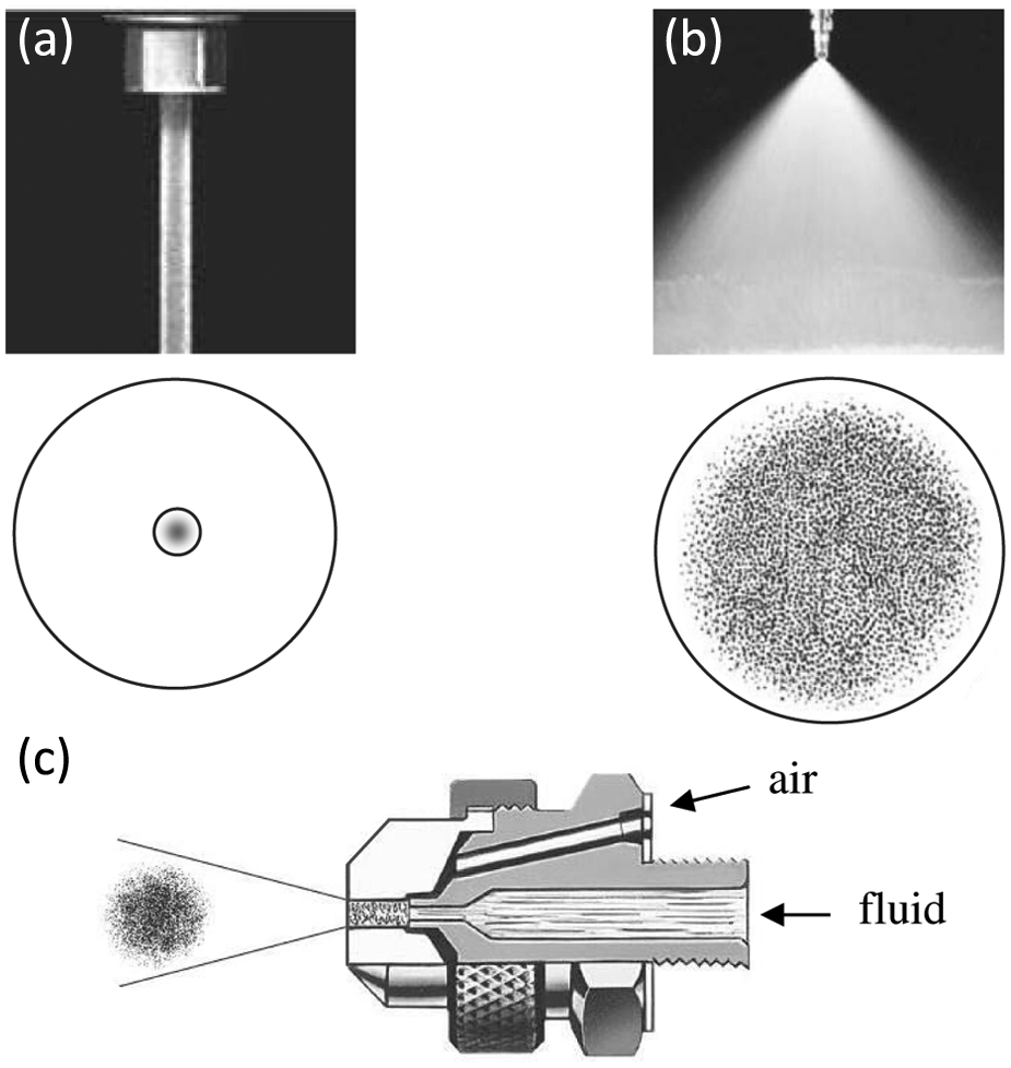
Nozzles used in the application methods with (a) jet, (b) pulverization and (c) atomization, that is, MQL/MQCF.
For controlling the flow rate supplied by the pump, a flow rate meter, Contech SVTL 1/2 model, was used with its corresponding digital meter. The general photographic view of the experimental setup is shown in Figure 3.
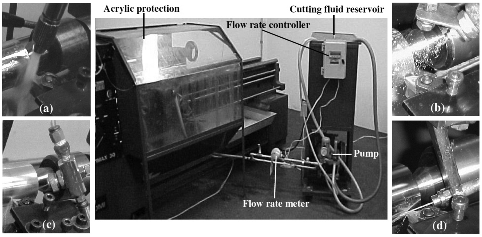
View of the experimental setup with the nozzles used in the applications: (a) conventional, (b) pulverized, (c) jet and (d) minimum quantity of fluid.
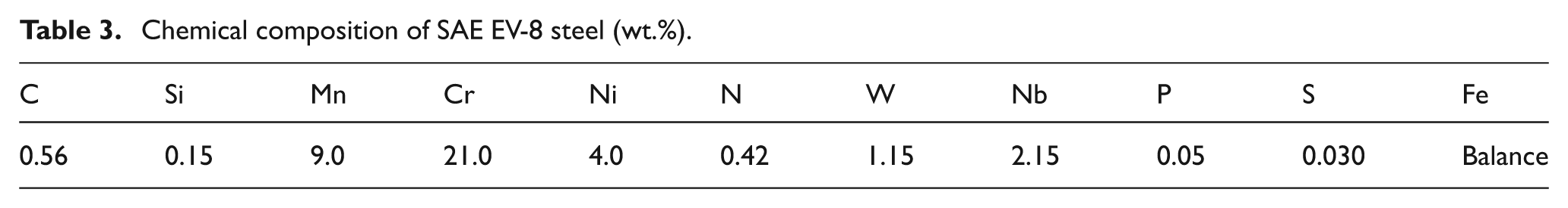
The machined material is a heat-resistant steel of austenitic structure, 21%Cr–9%Mn–4%Ni, with hardness 38 HRC, manufactured by Villares Metals, designated SAE EV-8 (or ISO 683-XV-8), which is recommended for manufacturing valves of internal combustion engines. Its thermal conductivity at 20 °C is 15 W/mK, and its chemical composition is given in Table 3. Figure 4 schematically presents the specimen dimensions used in the tests, which has a cutting length of 75 mm corresponding to one machining pass.
Chemical composition of SAE EV-8 steel (wt.%).
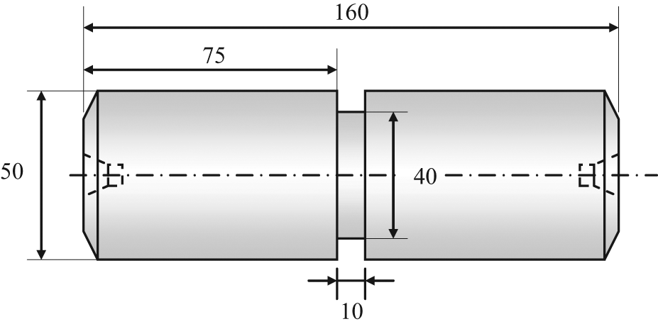
Specimen dimensions (in mm) for the machining tests.
During each fluid application method, the tool flank wear, cutting tool temperature, chip morphology, chip compression rate, cutting force, surface roughness and machined specimen microstructure were evaluated.
A digital camera coupled to an optical microscope was used to evaluate the tool flank wear, chip morphology and chip compression rate. A micrometer with conical tips was also used to measure the chip compression rate. The criterion established at the end of life was the average flank wear (VBB) ≥ 0.3 mm, according to the ISO Standard 3685 for tool life testing. The cutting tool temperature under each fluid application type was measured in a specific machining trial, during a single pass, using a polycrystalline cubic boron nitride (PCBN) insert, ISO designation CNMA 120408T-IB50, in which a K-type (chromel–alumel) thermocouple wire with a diameter of 0.4 mm was implanted. The cutting tools, PCBN and cemented carbide, have the same geometry. Figure 5 illustrates the toolholder set with the cutting tool in which a hole was made by electrical discharge machining for implanting the thermocouple until its tip touched the PCBN. Since PCBN wear resistance is much higher than cemented carbide, it was possible to use only one cutting tool for all temperature measurements without producing a significant wear value. With this procedure, the same position of the thermocouple in the insert for all experiments was ensured, which did not occur when the use of a carbide insert for each machining condition was tried.
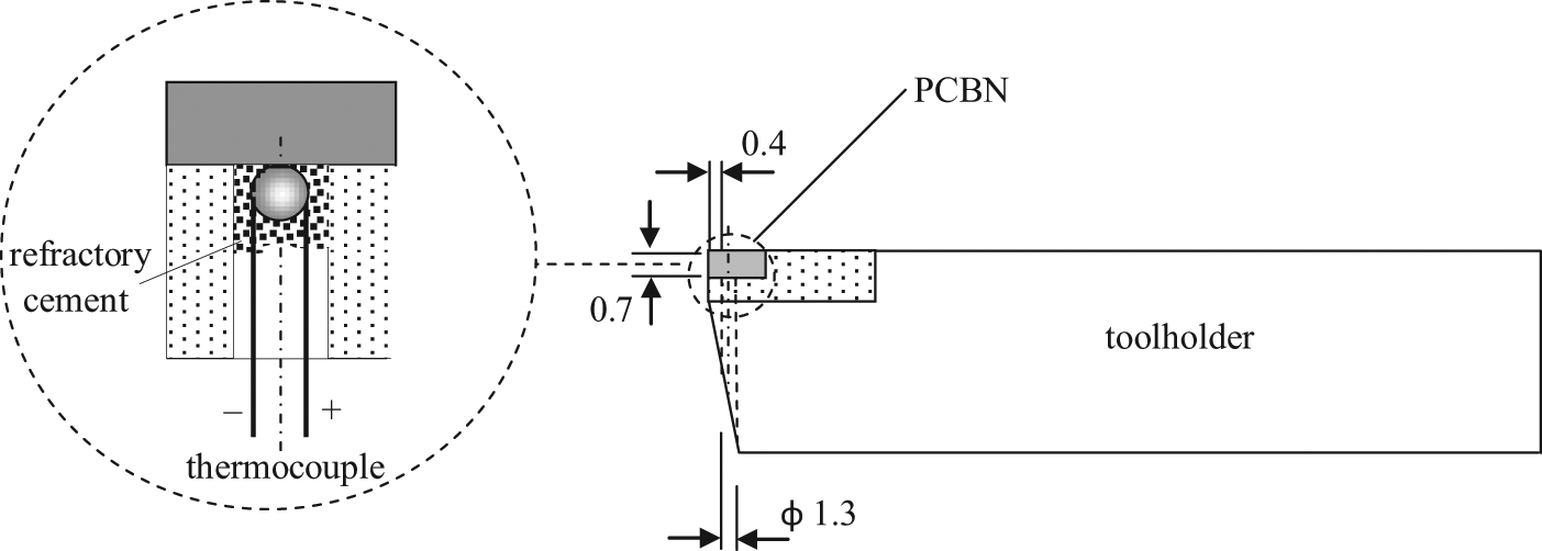
Cutting tool with thermocouple for comparison of machining temperatures in different fluid application methods.
The cutting forces generated during the machining tests were measured using a three-component Kistler piezoelectric dynamometer (9257 BA), and the signals were recorded on the computer by means of a LabVIEW 6.1 data acquisition system. The chosen surface roughness parameter was the arithmetic average (Ra) measured by a roughness tester Taylor Hobson, Surtronic 3+ model, adjusted for a cutoff length of 0.8 mm and a stylus tip radius of 2 µm. The value adopted was the average from three equidistant positions around the perimeter of the machined specimen.
After machining tests under each fluid application type were conducted, the subsurface microstructure of the specimen was analyzed in its cross section. For this, a grooved specimen divided into four elements was specially manufactured (Figure 6(a)). In the tests, each of them was machined in three consecutive passes according to every corresponding condition test, always using a new cutting edge. Then the elements were individually cut, and metallographic samples were prepared from their lateral faces (Figure 6(b)). From this procedure, the machining situation was simulated as real as possible and the samples’ microstructure modification that could occur if there was the cutting operation for its preparation is avoided to the maximum. When ended, the specimens were observed by a scanning electron microscope (SEM). The same samples’ section was employed to microhardness measurements using a microhardness tester Buehler MMT-3 with a load of 25 g under 10 s.
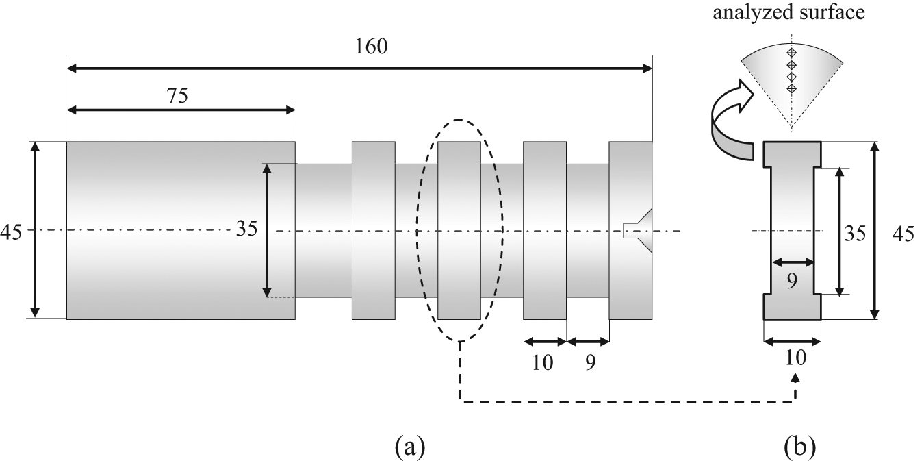
Illustration of (a) specimen and (b) sample removed for machined microstructure analysis.
Results and discussion
Figure 7 shows the tool life values obtained for each type of fluid application. In general, two noticeably different groups are observed, each one of them with close tool life values. In one of the groups, named group I, the MQCF, MQL and conventional methods make part, which are featured by presenting the lower values as tool life as application fluid pressure. It can also be noted that, except for the conventional method, they present the lower flow rate. In another group, the methods that reached the longest tool life have the cutting fluid application in jet form under high pressure in common.
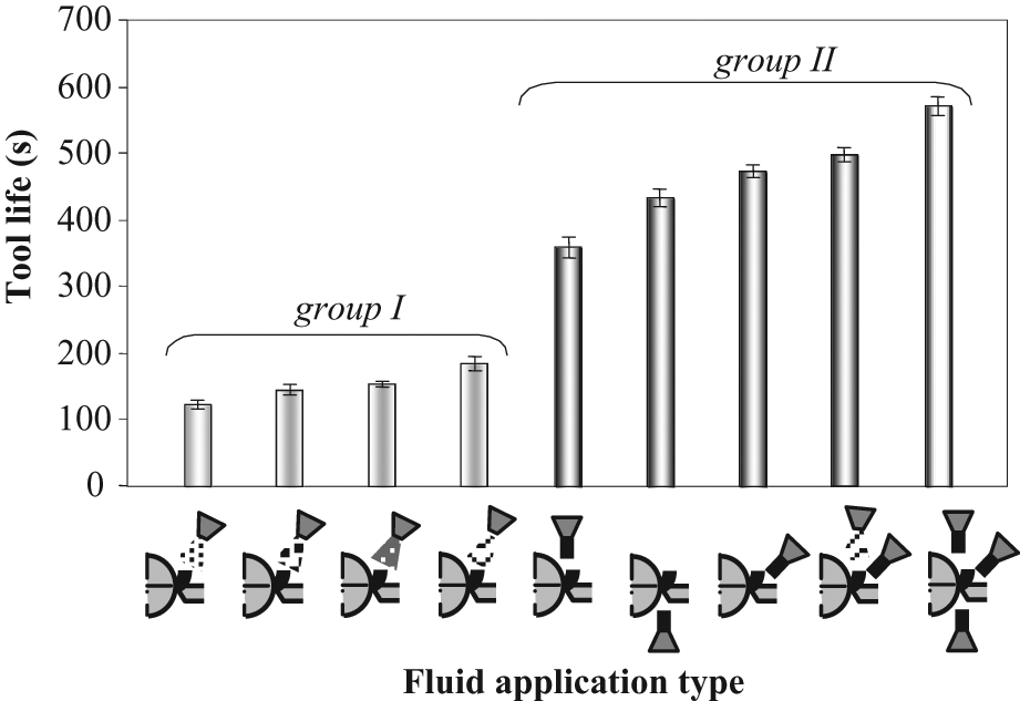
Tool life for each type of cutting fluid application.
In the group I applications, the longest tool life was obtained using the conventional method, unlike the MQCF method that presented the lowest value. This result shows that the largest fluid flow rate was determinant in the cutting tool cooling and its minor wear. Among the minimum quantity methods, the effect of vegetable oil lubricant in friction reduction at the chip–tool interface suggests that it is more effective in the minimization of tool wear than the cooling action of the cutting fluid. This results in a longer life with MQL than with MQCF. The tool life with the pulverization method is sorted between the conventional and MQCF methods; its flow rate value is also intermediary between these two methods, confirming the importance of the cutting fluid volume in the low-pressure applications.
Figure 8 shows the cutting tool temperature for each fluid application method. The methods under high pressure generated the lowest temperatures during machining. Considering the low-pressure methods, the temperatures were lower when the cutting fluid quantity applied was larger. The MQL method presents the highest temperature, however its life has not been the lowest. This suggests the importance of lubrication on the tribological conditions of machining in applications where the flow rate is too low.
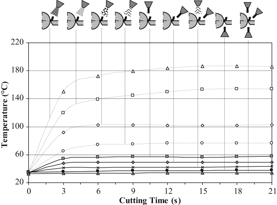
Cutting tool temperature in different types of fluid application.
In spite of a short difference among the temperature values in the group of applications under high pressure (group II), the simultaneous method was the one that provided the longest tool life (see Figure 7). Therefore, together with the combined method, both of them have the highest fluid consumption, corresponding, respectively, to triple and double applied volume by the C/T jet, whose method had the best performance among those that used just one jet. The great result of the C/T jet can be attributed to the highest fluid efficiency for reaching the tool zone under the highest temperatures, which are located close to the tool tip and adjacent to the secondary shear plane. Associated to the deepest penetration of the cutting fluid, the chip suffers a bend and it is pushed off the rake face. Because of this, the chip contact length must be diminished, even if only in the sliding region, which contributes to tool wear minimization. The fourth application in decreasing length life occurs with the T/W jet, whose result is worse than the C/T jet 10% only, since this application allows the fluid jet to reach directly the contact region between the tool and workpiece, where the flank wear develops. Although the highest temperatures are not exactly there, this location is pretty close to them and, though the main role of the cutting fluid is to cool, its insertion between workpiece and tool seems to create tribological conditions able to attenuate the increase of a tertiary shear zone, which can gain importance, whereas the flank wear advances and the contact area increases. Among the high-pressure applications, the W/C jet produces the shortest cutting tool life. This inferior performance can be credited to the direction of the jet on the back of the chip. In spite of cooling the shear primary zone and contributing to the minimization of the heating flow to the tool, it does not put the cutting fluid in direct contact with the tool, where the highest temperatures are concentrated. Finally, in this method, the fluid jet tends to push the chip against the tool rake face, resulting in an increase in chip contact length and tool wear.
Referring again to Figure 8, it is observed that the order of temperature values was opposite to the order of the tool life values, that is, the temperature increased from simultaneous jets to the MQCF method, while the tool life increased from the MQCF method to simultaneous jets. An exception is noticed for the T/W jet application, whose temperature was the second lowest, but it was not the second longest. This dissimilarity may be justified due to the influence of the thermocouple inserted locally into the cutting tool close to the rake face, where the cutting fluid directly reaches it.
Figure 9 shows the surface images of the cutting tool rake face in the group I applications when the end life criterion was overtaken. In all the conditions, it can be seen that the tool wear is located in the tip region and highly concentrated below it, as it can be seen in an image of a tool life in its end when a conventional fluid application is used (Figure 10). This is a common feature of certain difficult-to-machine steels, such as Inconel, Waspalloy and the valve steel used in this work. They have high mechanical resistance and low thermal conductivity, which becomes difficult the cutting tool heat dissipation during the machining. In general way, a qualitative evaluation of the tool wear indicates the prevalence of the abrasive mechanism without observing the buildup edge formation. Among the four applications, the conventional method shows the longest maintenance of cutting tool geometry, suggesting that the lowest temperature from this method has collaborates in this sense.
Cutting tool wear in the methods: (a) MQCF, (b) pulverized, (c) MQL and (d) conventional.
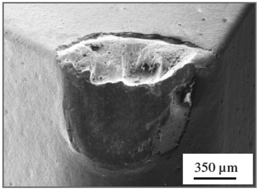
Typical cutting tool wear when machining an SAE EV-8.
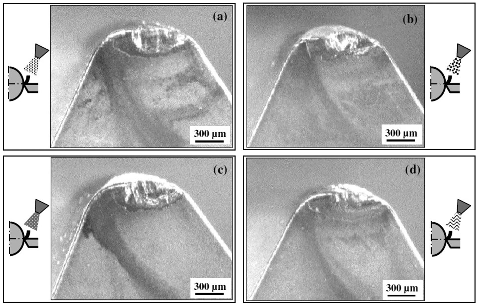
The cutting tool wear in the methods that use cutting fluid jet is shown in Figure 11. The W/C jet presents the largest worn area, probably due to the longest chip contact length (Figure 11(a)) and the highest cutting tool temperature (Figure 8). The cutting tool geometry was better kept when at least one fluid jet was toward the chip–tool interface (Figure 11(c) to (e)).
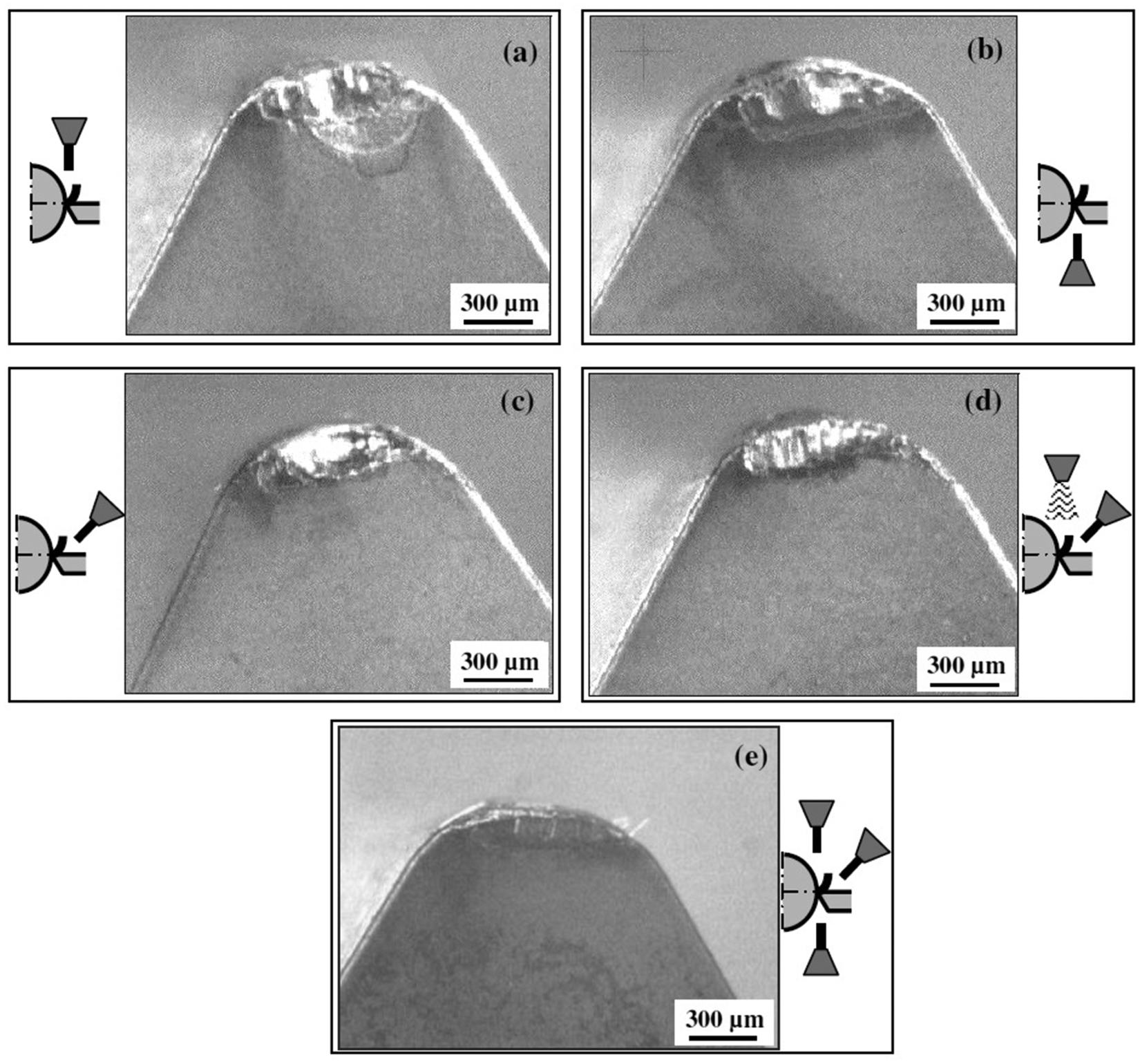
Cutting tool wear in the methods: (a) W/C jet, (b) T/W jet, (c) C/T jet, (d) combined and (e) simultaneous jets.
Figure 12 exhibits the morphology of chips obtained in the different types of fluid application. It can be seen that the generated chips in the low-pressure methods had helical continuous form and the size of radius curvature in common. Since the fluid is directed to the back of the chip in these applications, the cooling of its superior portion may have produced enough shrinkage to curl them. In the case of the MQL method, its poorest cooling action made the radius of curvature slightly larger.
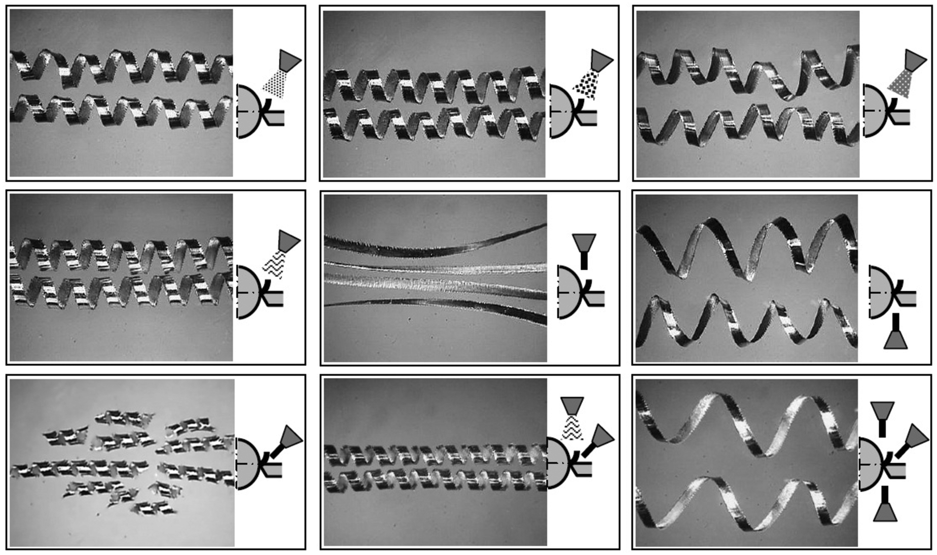
Aspect of chips generated in turning under different types of fluid application.
In the jet methods, the chips assume different forms according to the direction of fluid application. The W/C jet is the most distinct condition, due to the continuous “ribbon” chip whose main cause is the jet hydraulic power on its back, which pushes it against the tool. On the other hand, the C/T jet chip is the most fragmented and has a small radius of curvature. This indicates that, in fact, the fluid must have acted hydraulically under the chip, moving it away from the rake face. Similar to most of the methods, the T/W jet shows a helical chip with a well-defined shape and a large radius of curvature, probably due to absence of the influence of any jet pointed out to the chip. In the combined method, which added the conventional application to the C/T jet, the chip formation seems to have suffered a mild interference from the flood fluid on the back of the chip. These chips assumed the helical form without breaking, with radius of curvature slightly larger than the C/T jet applied alone. In the simultaneous application, the helical form presents a large radius of curvature tending to the ribbon form. This can be attributed to the prevalence of jet force on the back of the chip in relation to the jet at the tool–chip interface.
Figure 13 depicts the force components of the W/C jet and the C/T jet operating on the chip, where (
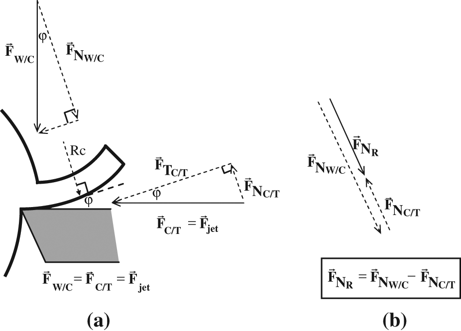
(a) Interaction between W/C and C/T jet forces on the chip in the simultaneous method and (b) their results.
The chip compression rate, usually denoted by λ, is given by the ratio of chip thickness (t2) and undeformed chip thickness (t1) according to equation (1). This parameter is a classic indicator of the chip deformation amount aiding in the analysis of the consumed energy in the material removal.18,25 From the geometric relations of chip formation is seen that the primary shear plane angle can be associated to λ and tool rake face angle (γ0) as expressed in equation (2).25,26 Consequently, for decreasing values of λ, there is an increase in the primary shear plane angle, thus a more favorable machining condition that requires less specific energy. Equation (3) makes clear the influence of the tool rake angle (γ0) and friction (µ) at the chip–tool interface on the chip compression rate (λ) 27

The chip compression rate produced by the low-pressure methods had an average value around 1.60, with a close difference among them, as depicted in Figure 14. Otherwise, in the single fluid jet methods, the values of λ were quite diverse, that is, of 1.25 (W/C jet), 1.38 (T/W jet) and 1.84 (C/T jet). Even that
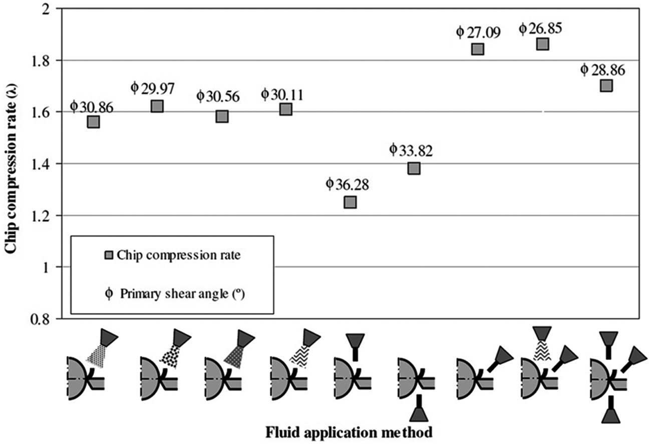
Chip compression rate (λ) and primary shear angle (
Figure 15 exhibits the values of microhardness measurements on the layer below the specimens’ machined surface in all investigated conditions. It is noted that the microhardness is higher near the surface and progressively diminishes toward the interior of the specimen until it reaches the base material mean hardness, around 405 HV. The greatest hardness value can be associated with the highest density of grain dislocation present in the plastic deformation of largest intensity. As the SAE EV-8 steel presents an austenitic structure, this deformation process results in a material hardening by work hardening in the layer beneath the machined surface, similar to the effect found in machining of an Inconel 718. 11 Under temperature increase, there is a greater propensity for plastic deformation of workpiece subsequent layer left by the tool pass and, therefore, a hardness increase and a deepening of the affected layer. Thus, the efficiency of the fluid application method may be associated with the extension of the plastically deformed layer, as the results in Figure 15 suggest, which indicates that the low-pressure methods (Figure 15(a)) produced deeper deformation than the high-pressure methods (Figure 15(b)). Whereas the matrix material was achieved with a depth around 170 µm for the conventional method, the most efficient among those of low pressure, the depth in most efficient methods of fluid jet was 140 µm. From these applications, the simultaneous, combined and C/T jet stood out.
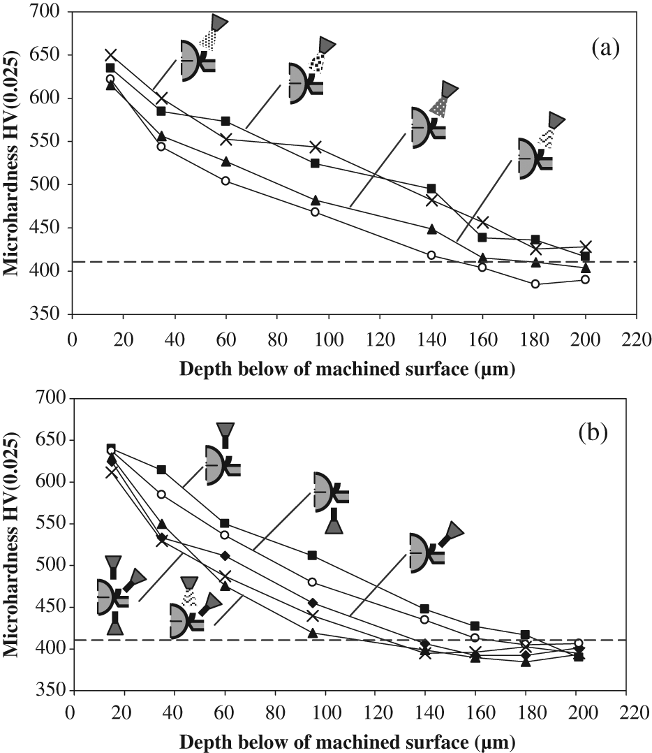
Microhardness below the machined surface under application methods of (a) low and (b) high pressure.
Figure 16 reveals the microstructures below the specimen’s machined surface under the conventional method (Figure 16(a)) and C/T jet method (Figure 16(b)). The resulting grains from the conventional application are more deformed than those from the C/T jet, confirming the most propitious condition of the high-pressure methods compared to the low-pressure methods. In the microstructure, the arrow points to the precipitates of chromium carbide present in SAE EV-8 steel, whose composition was identified by means of energy-dispersive X-ray spectroscopy (EDX) analysis.
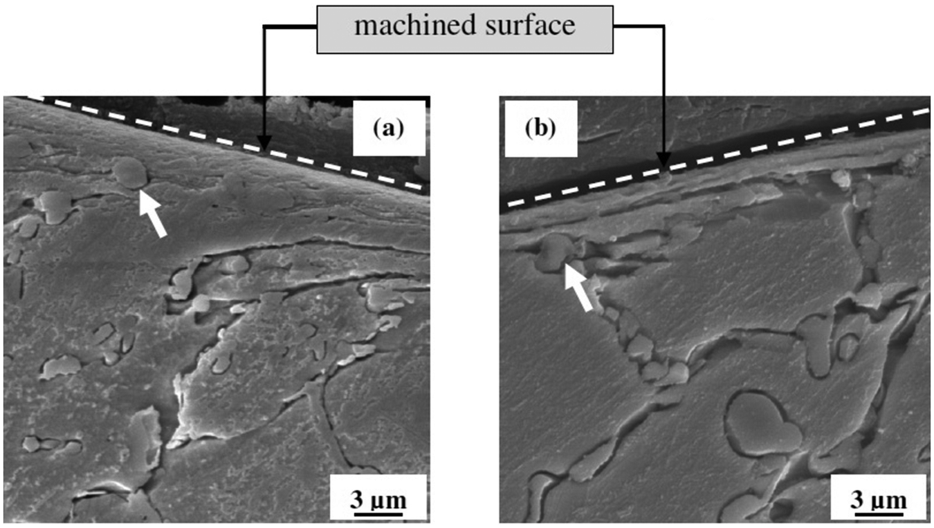
Microstructure of the specimens after machining under (a) conventional method and (b) C/T jet.
Figure 17 depicts the cutting force at the beginning of 40 s of machining, equivalent to one pass of the cutting tool along the workpiece. After one pass, the cutting tool was only slightly worn, without significant alteration of its geometry depending on the application method. Just a small portion of the measured force value may have been caused by the cutting tool wear.
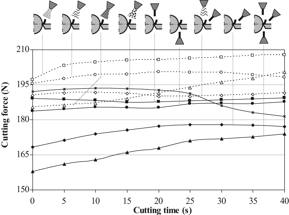
Cutting force in the fluid applications along the first machining pass.
In general, it can be observed that the applications with fluid jet produced the lowest cutting force. With respect to the T/W jet, this is due to the direct fluid action between the cutting tool and the workpiece, which, because of its cooling and lubricant function, contributed to friction minimization and the maintenance of size of tertiary shear zone restraining its dramatic increase. The progressive enlargement of the contact area makes the heat flow grows quickly through it, increasing remarkably the flank wear and cutting force. 18 The C/T method allows easier access of cutting fluid to the secondary shear zone, where the temperatures are highest, and there are intense friction and development of diffusion and/or adhesion (attrition) mechanisms. In this case, the presence of the fluid minimizes these negative factors offering superior tool life with inferior machining force, as occurs with all methods that use the cutting fluid at the tool–chip interface, indicated in Figure 16. In relation to the W/C jet, the chip generated assumes the continuous ribbon form that presents as characteristic a low strain rate. This suggests that the fluid under high pressure inhibits the chip lamellar sliding, consuming less energy in shearing, shortening the chip formation mechanism and providing higher speed. All these assumptions regarding this method are corroborated by its low chip compression rate (λ = 1.25) and cutting force inferior to the low-pressure methods. In fact, the increase in the shear plane angle, due to decrease in chip compression rate, reduces the area of the shear plane and consequently decreases the cutting/friction force.1,6
According to Kato et al. 28 and Toropov and Ko, 29 the chip–tool contact length (Lc) can be estimated successfully by equation (4).
This means that the W/C jet must have the lowest Lc, as is verified, once its λ is the lowest among all the investigated methods. However, the chip is forced against the rake face of the cutting tool by the fluid jet action. In this case, even if the pressure produced by the jet is not enough to increase the sticking zone, the sliding zone was enlarged as suggested in Figure 11(a), which shows a large dimension of wear, creating adverse conditions for the tool, although the cutting force has been kept in relatively low levels, as shown in Figure 17.
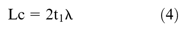
Among the low-pressure methods, the MQL application indicates to have supplied the best initial tribological conditions once their forces were lower, but they gradually seem to have been influenced by the progressive tool wear. After the first pass, deep changes occurred in the tools influencing the cutting forces that significantly increased, as shown in Figure 18. Even so, the most favorable cutting conditions continued with fluid jet application, expressed by the lowest machining forces. It is noted that the sequence of force values at the end of the applications is disposed in reverse order of tool life (see Figure 7). Thus, the MQCF application presented the highest cutting force and lowest tool life, while the simultaneous jets had the lowest force and longest life. An exception occurred in the order of the forces between W/C and T/W jets. Although in the initial instant, when the cutting tools were still preserved, the forces showed the same order obtained in the evaluation of tool life.
Cutting force in the fluid applications after the first pass.
The surface roughness behavior of specimens in the tests using the fluid jet methods is presented in Figure 19. In this figure, the average values of the surface roughness in the group I applications were added. Similar to the other analyzed outputs, the jet applications had a better performance, especially the C/T jet, which produced a low and constant surface roughness, which increased only at the end of tool life. The order of final surface roughness values also followed the same order of cutting tool life values. The exception took place with the simultaneous jets. Despite having the greatest cooling capacity, the simultaneous jets seem to suffer the influence of two other jets that do not act in the reduction of contact length.
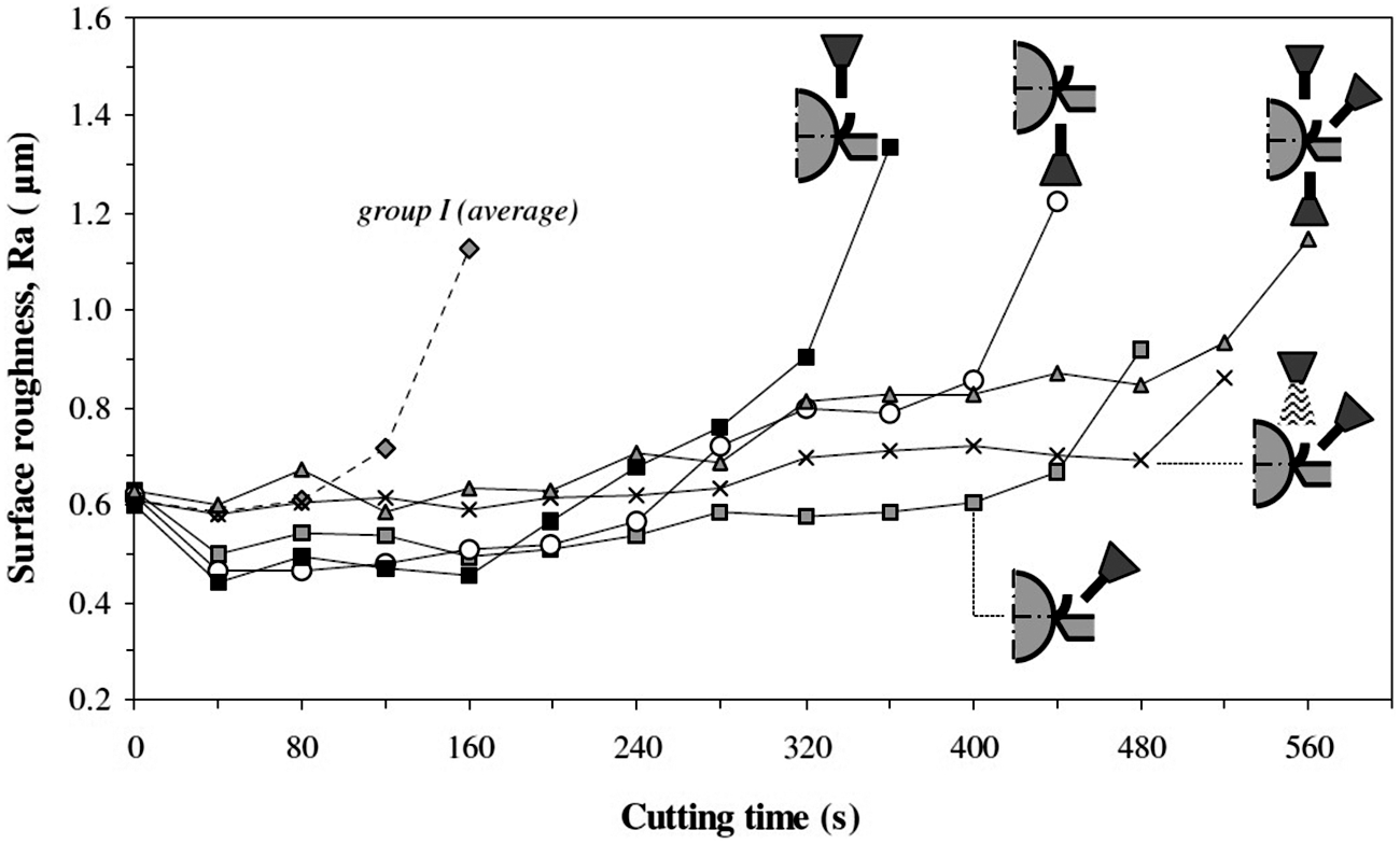
Surface roughness of specimens in the applications with cutting fluid jet (group II).
As shown in Figure 20, in low-pressure fluid applications, the methods with reduced flow rate exhibited an increase in surface roughness at the end of tool life compared with the conventional method. The MQL method draws attention because it produced the lowest surface roughness values close to the last pass. Next, with the progressive rise of cutting tool wear and machining force, this method did not reach the similar tribological conditions, generating dramatic surface roughness increases at the end of the last pass. If the surface roughness was adopted as a decisive criterion for the parts manufactured, the MQL method could be considered a great candidate among the fluid application methods of group I. For this, the operation interruption should be in the next to last pass, before the cutting tool reaches its end of life.
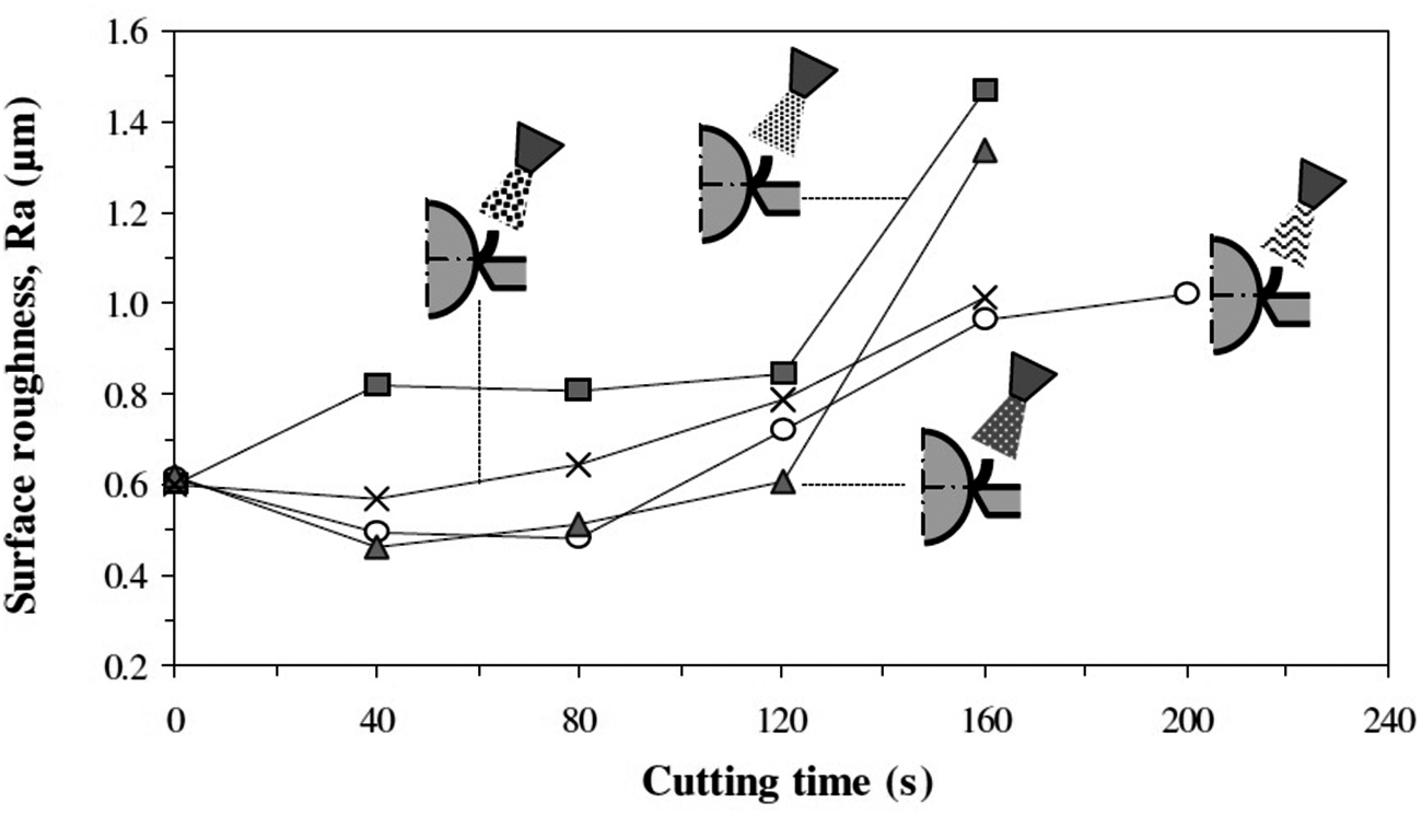
Surface roughness of specimens in the applications of low pressure (group I).
Figure 21 presents the cutting tool life as a consequence of the combination of pressure and flow rate values for each application method. It is noted that the lowest pressure and fluid flow rate values, independent of the application method, resulted in the lowest tool lives. With the large rise only of the flow rate, a small increase of tool life is obtained, such as occurred with the conventional method. On the other hand, with a stable flow rate, a dramatic increase in tool life was reached only with a rise in pressure, as occurred using any individual jet. But, if the flow rate is considerably increased, the tool life grows again in a modest way, as verified in the simultaneous and combined methods compared to the C/T jet, which only uses a half and one-third of the flow rate employed in the two methods, respectively. Since the rise in pressure has a limited effect on the tool life and/or temperature in the cutting zone, as can be inferred from several studies,6–9,24 the direction variation of the fluid jet, for constant pressure and flow rate, shows notable influence on the tool life, as it was found here with the positions of single jets toward the workpiece–chip, tool–workpiece and chip–tool.
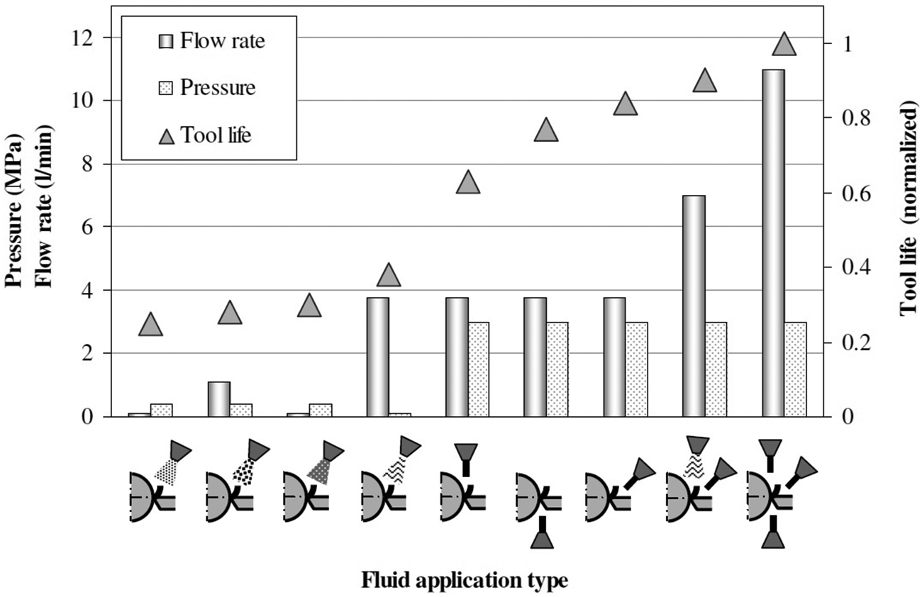
Effect of pressure and flow rate on tool life under various fluid application methods.
Conclusion
Based on the results obtained in this study, the following can be briefly concluded:
The performance of the turning operation can be significantly modified by the cutting fluid application method.
The longest tool lives and the lowest surface roughness were reached by methods that involved fluid jet under high pressure.
The methods using combined application (C/T jet and conventional) and simultaneous jets (C/T, W/C and T/W) achieved the longest tool lives, but with double and triple the flow rate used in the single jets, respectively.
The C/T jet highlighted among the high-pressure methods because it produced one of the best performance just using a flow rate equal to the conventional method. In this case, the pressure supplied (3.0 MPa) seems to have been enough to act like a hydraulic wedge, bringing the benefits of its presence.
T/W jet revealed to be more efficient than W/C jet, which had the worst performance among the singly applied jets.
The conventional method produced the best results among the applications under low pressure, which includes the reduced flow rate methods. The MQL method was distinguished among the reduced flow rate because of its low surface roughness during the major part of tool life.
The cutting force, cutting tool temperature and surface roughness of the specimens portrayed, largely, the behavior of tool life obtained by different application fluid methods.
The variation of fluid application type within the low-pressure methods practically did not interfere in chip form and chip compression rate, whose magnitude ultimately indicates the energy consumption in machining. In turn, the jet direction change is able to decisively modify the chip form and chip compression rate.
The microstructure of the machined specimens under high-pressure methods suggests less alteration than in the low-pressure methods.
Footnotes
Acknowledgements
The authors would like to thank Villares Metals’ engineers, Celso A Barbosa and Alexandre Sokolowski.
Funding
This research received funding from Fundação de Amparo à Pesquisa do Estado de São Paulo (FAPESP), Brazil (01/06867-9).