
Abstract
A thin plate like a bipolar plate for a proton exchange membrane fuel cell is one of the core parts for improving the power density in a fuel cell. Stainless steel has excellent characteristics in terms of electrical resistivity, density, and thermal conductivity. Furthermore, stainless steel, instead of graphite, is used as a bipolar plate because it is cheaper and easier to machine. Therefore, in this study, a stainless steel alloy is selected as the ideal material for a bipolar plate. In this article, the results of feasibility experiments are presented; these experiments are performed with the aim of developing fuel cells using stainless steel bipolar plates with multiple channels. In this investigation, a dynamic load was applied, and the formability of microchannels was estimated with different punch pressures and die roundness, using a thin sheet metal of SUS304 with thicknesses of 0.3 and 0.1 mm. In the case of the die roundness of 0.1 mm, the formability is optimized with a sine wave dynamic load that has 90 kN of maximum pressure and five cycles of punch movement. The experimental results demonstrate the feasibility of the proposed manufacturing technique for fabricating bipolar plates.
Introduction
Recently, studies on renewable energy have been conducted to solve the problems of environmental pollution caused by the use of fossil fuels, which contribute to global warming. In particular, fuel cells, which are one of the sources of renewable energy, have features such as a high level of efficiency, non-polluting characteristics, low noise, and ease of site selection. In addition, a variety of fuels such as hydrogen, natural gas, and methanol can be used as energy sources. Hence, it has become popular as the next generation of alternative energy technologies.1,2 A proton exchange membrane fuel cell (PEMFC) is one of the non-polluting perspective energy sources to use hydrogen and oxygen as fuels. PEMFCs for reducing the atmospheric gases given out by cars are attracting attention as environmentally friendly alternatives. However, PEMFCs are difficult to commercialize in terms of price, as compared to gasoline engines. For this reason, studies on a PEMFC system have been conducted from the viewpoint of reducing the weight and cost of a bipolar plate with more than 50% of the manufacturing cost of the stack. Among the various components of a fuel cell stack, bipolar plates account for 60%–80% of the weight of the stack and 30%–45% of the price of the stack; therefore, this plate is one of the most important components in terms of commercializing a PEMFC.3,4
In general, a unit cell that makes up the fuel cell stack consists of a membrane electrode assembly (MEA) and bipolar plates. The bipolar plates are connected on both sides of the MEA and have functional channels at the junction side that moves the fuel and oxygen for electricity generation. In addition, bipolar plates are the core components for collecting the current, removing heat from the stack, and preventing leakage of the reactants. Owing to these requirements, materials for bipolar plates should have good electrical conductivity, good thermal conductivity, good corrosion resistance, low weight, low material costs, and low processing costs. 5 To date, most of the materials used for the bipolar plates of fuel cells are graphite-based materials. Although the materials commonly have excellent electrical conductivity and corrosion resistance, the graphite-based bipolar plates are very expensive owing to conventional machining methods such as those involving a lathe. Moreover, graphite-based bipolar plates can be easily destroyed because of their brittle fracture characteristics; they also have low gas permeability and low productivity. To date, alternative materials such as current graphite/carbon matrix composites, titanium, aluminium, and stainless steel are being studied for use as bipolar plates. Of these materials, stainless steel has a relatively low cost and excellent workability, mechanical strength, and electrical conductivity.
Bipolar plates have been fabricated by computer numerical control (CNC) milling; 6 stamping/embossing;7,8 hydroforming;9,10 extrusion; 11 etching; 12 lithography, electroplating, and molding (LIGA)-electroforming; 13 die casting; 14 and so on. In processes involving the machining and shearing of a metallic bipolar plate, the processing cost is higher than the cost of the materials. Therefore, stamping processes are being extensively studied for mass producing bipolar plates to reduce manufacturing costs; these processes have been applied for fabricating the actual bipolar plate for fuel cells. However, microchannel dimensions cannot be precisely stamped as designed owing to the forming limitation; moreover, the performance or efficiency of the fuel cell is decreased by springback due to the elastic recovery of the plate.15,16 In this study, to improve the formability of bipolar plates with serpentine-type microchannels, dynamic loads with sine, square, and ramp waves were loaded during the stamping process. In addition, the type and pressure of the dynamic load and the number of cycles suitable for stamping were derived in this study, and the formability of the bipolar plates was evaluated by comparing a bipolar plate fabricated by the existing stamping process. For this study, 0.1 and 0.3 mm were chosen to evaluate the formability with a variation of the roundness of the microchannel. The forming depth and thinning were measured and compared under different loading conditions.
Fabrication of bipolar plate under dynamic load
Experimental set-up
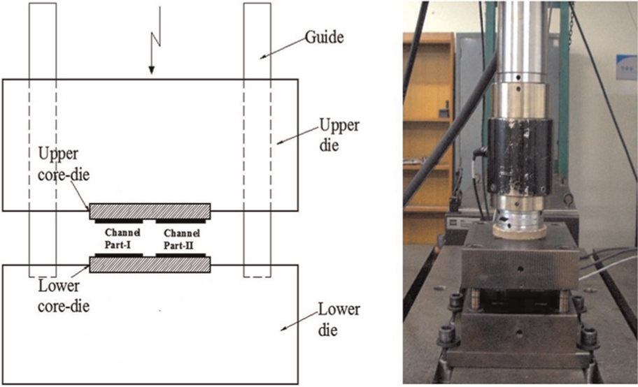
A 25-ton dynamic material testing system (MTS) was employed as a stamping machine. The MTS having the functions of fine velocity and load control is suitable with the equipment required for the stamping process to achieve the precise control of a variety of dynamic loads with sine, square, and ramp waves. The deformation behaviour and the defect of the stamped thin plates were observed by optical microscopy, and the formability was evaluated by using the scanned image of the cross section of the bipolar plate.
Figure 1 presents a schematic diagram of stamping for this study. The experimental equipment is largely made up of a punch, an upper die, the channel Part-I, the channel Part-II, and a lower die. The upper and lower dies were commonly made of AISI H13 (STD61) with excellent characteristics for wear and heat distortion. The core dies for fabricating the microchannels were designed, so that they could be assembled with the upper and lower dies and be substituted with a die with a different shape and for maintenance. In addition, guidelines have been set to prevent warping during the forming process.
Schematic diagram and photograph of the stamping die
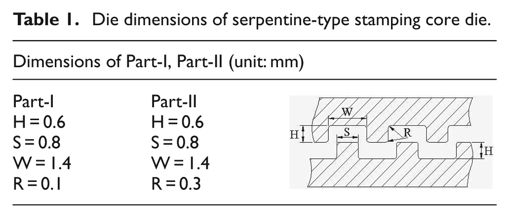
Figure 2 shows the schematic diagram of upper and lower core dies for fabrication of the thin metal plate with serpentine shape. As can be seen in Figure 2(a), two types of upper core dies (Part-I and Part-II) were designed to evaluate the formability with respect to the roundness (R0) of the microchannel. The dimensions are 54 mm horizontal length and 50 mm vertical length (54 mm × 50 mm). Figure 2(b) illustrates the two types of the lower core dies with the same lengths of the upper die. Their specific dimensions are listed in detail in Table 1. The two types of dies were manufactured with the roundness (R0) of 0.1 and 0.3 mm, respectively.
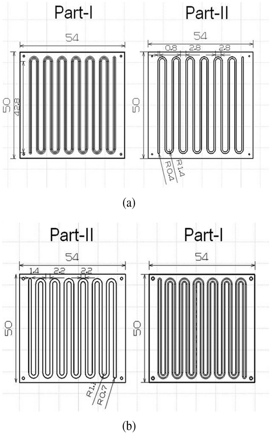
Schematic diagram of core die with cavity of serpentine channel: (a) upper die and (b) lower die.
Die dimensions of serpentine-type stamping core die.
Experimental condition and procedure
Figure 3 shows the schematic diagram of the stamping process. As can be seen in this figure, the thin metal plate is deformed, and then, begins to fill the cavities of the dies when the upper die pressurizes the thin plate on the lower die. During this process, the microchannel of the plate is continuously stamped by the dynamic load with sine, square, and ramp waves for the number of cycles to be controlled.
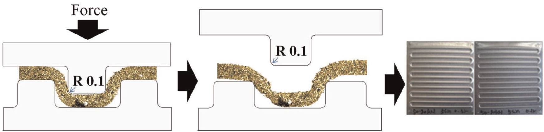
Sketch of stamping process: (a) press and (b) unbending.
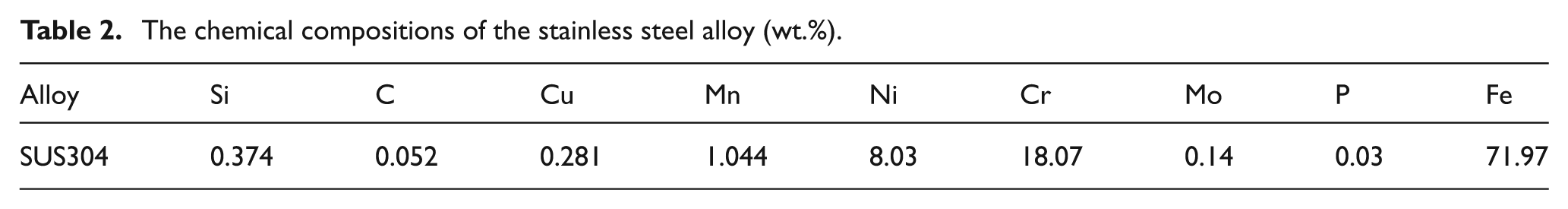
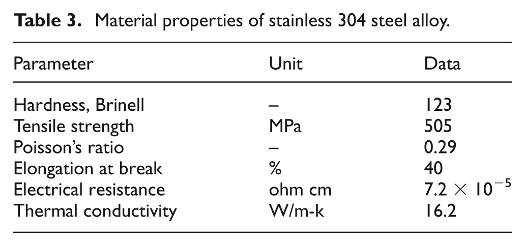
In this study, the material of the plate was SUS304. The chemical composition and the mechanical properties are listed in Tables 2 and 3, respectively. The thickness and size of the plate were 0.1 mm and 55 mm × 50 mm, respectively.
The chemical compositions of the stainless steel alloy (wt.%).
Material properties of stainless 304 steel alloy.
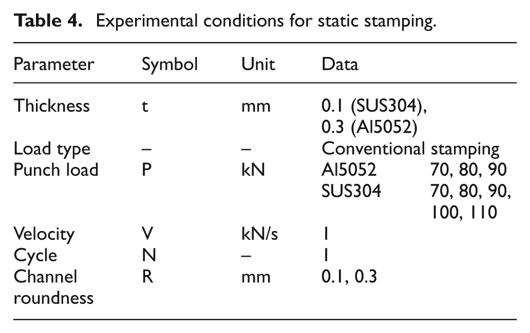
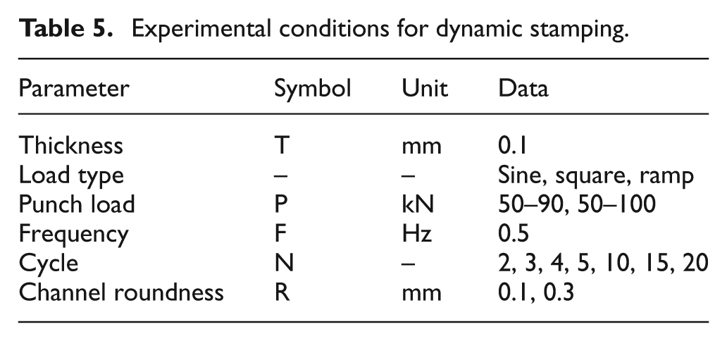
Tables 4 and 5 list the experimental conditions under the existing static and dynamic loads, respectively. As seen in these tables, the variables are the type of load, punch pressure, velocity and frequency, the number of cycles, and channel roundness.
Experimental conditions for static stamping.
Experimental conditions for dynamic stamping.
Experimental results and discussion
Figure 4 shows a plot of the punch displacement (δ) against the punch pressure for the static stamping process for the thin plate with a thickness of 0.1 mm. As can be seen in this figure, at least 100 kN was required for the forming depth of 0.6 mm. Meanwhile, the fabricated bipolar plate samples were cut to measure the forming depth from the cross section.
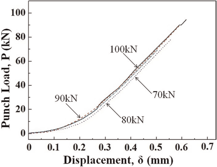
The load–displacement curves at punch load of stamping (SUS304).
Figure 5 shows the forming depth of the bipolar plate fabricated under the existing static load, with regard to the channel roundness. Regardless of the channel roundness, the forming depth of the microchannel monotonically increased depending on the punch load; however, over a punch load of 100 kN, there was only a slight depth change. Thus, 100 kN was set as the maximum punch load for the dynamic load.
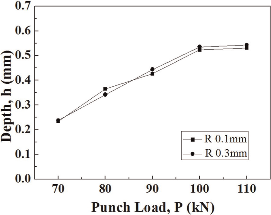
Channel depth at different punch load and die radii.
Figure 6 shows a plot of the punch load against displacements, with regard to the type of dynamic load with the maximum load of 100 kN, based on the result obtained from Figure 5. Among them, the dynamic load with the square wave showed the most rapid load variation and the longest loading time.
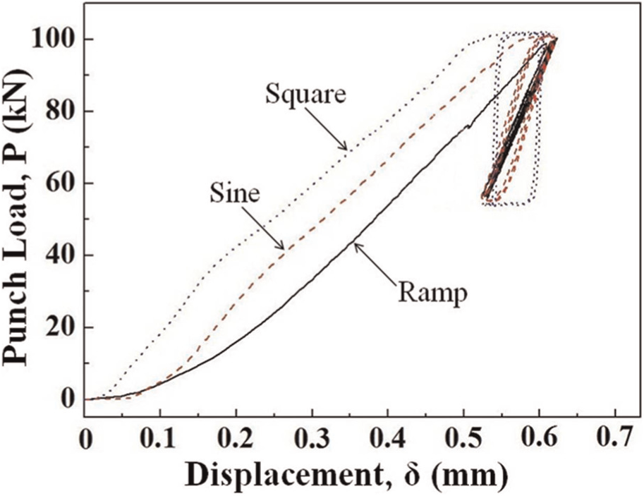
The load–displacement curves at dynamic load (SUS304).
Figure 7 shows the variation in the forming depth with respect to the number of load cycles, with regard to the type of dynamic load used. Figure 7(a) presents the forming depth with a variation of the number of load cycles under the dynamic load with the sine wave having a maximum load of 100 kN. As shown in this figure, the forming depth of the thin plate with the roundness of 0.3 mm was in proportion to the load cycles, but after five cycles, the increase in the depth was marginal. Figure 7(b) shows the forming depth with a variation of the number of cycles under the dynamic load with the square wave having a maximum load of 100 kN. As seen in this figure, the forming depth showed a higher value under the dynamic load with the square wave than any other dynamic loads. Moreover, the tendency of the increase was similar to that shown in Figure 7(a). Figure 7(c) shows the variation in the forming depth with the number of cycles under the dynamic load with the ramp wave having a maximum load of 100 kN. Unlike in the other types of dynamic loads, the forming depth under the dynamic load with the ramp wave showed a relatively linear increase. However, it also shows the lowest value among the dynamic loads.
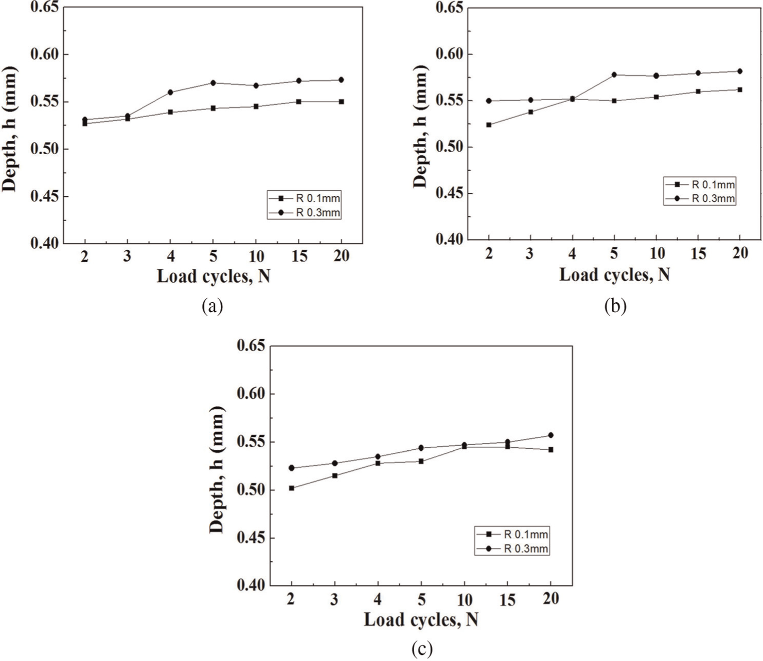
Relations between dynamic load of cycle number and channel depth: (a) dynamic load–sine, (b) dynamic load–square, and (c) dynamic load–ramp.
Figure 8 shows the results of the comparison of the forming depths of the bipolar plates under the existing static load and dynamic load with the square wave, which showed the maximum depth, as shown in Figure 7. As plotted in this figure, the forming depths of the thin plate with the roundness of 0.1 and 0.3 mm fabricated under the static load were 0.523 and 0.542 mm, respectively, and the depths under the dynamic load with the square wave were 0.562 and 0.582 mm, respectively. From the results above, the forming depth was commonly improved by about 7%.
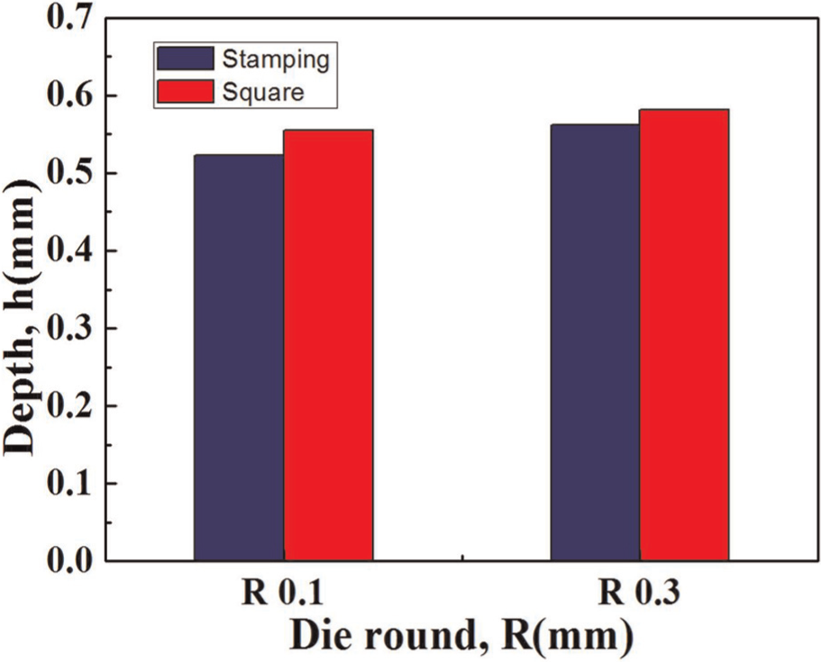
Channel depth concerning dynamic load (20 cycles) and stamping.
Figure 9 shows the definition of thinning (th) for the evaluation of formability in terms of the forming depth. In this study, thinning is defined as the difference between the thickness of the formed plate and the initial thickness.
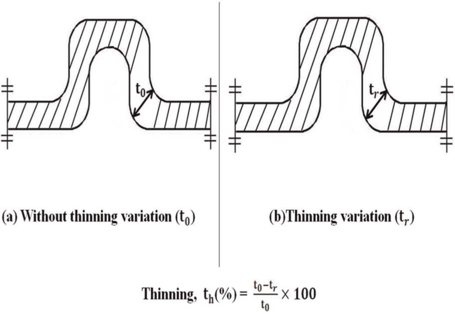
The definition of thinning,
Figure 10 presents the cross section of the thin plate fabricated at the various conditions. The stamping depth was measured, and the shape of the microchannel was analysed on the basis of the cross section.
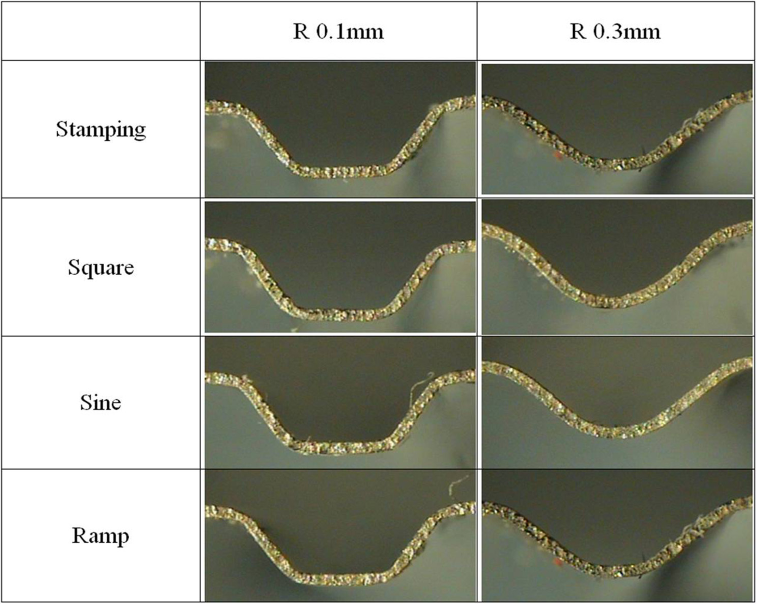
Section view according to different radii and forming types (punch load: 50–100 kN, frequency: 0.5 Hz).
Figure 11 shows the thinning of the microchannel for the traditional forming process. The thinning of the thin plate with the channel roundness of 0.1 mm fabricated by the existing forming process was about 10.7%, and the thinning of the plate fabricated under the dynamic loads with the sine, square, and ramp waves was 7.8%, 9.4%, and 10.4%, respectively. On the basis of this result, the maximum thinning of the bipolar plate occurs in the stamping condition and the minimum thinning occurs under the sine wave, and it contributed to improving the thinning by up to 28%. However, the thinning of the bipolar plate with the channel roundness of 0.3 mm showed little difference under the different dynamic loads.
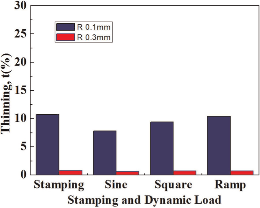
Comparison of thinning between conventional stamping and dynamic load stamping (stainless steel) (punch load: 100 kN, punch velocity: 1 kN/s, dynamic load frequency: 0.5 Hz).
Figure 12 shows the cross section of the bipolar plate fabricated under the various cycling conditions. The thinning was observed and measured through the cross section.
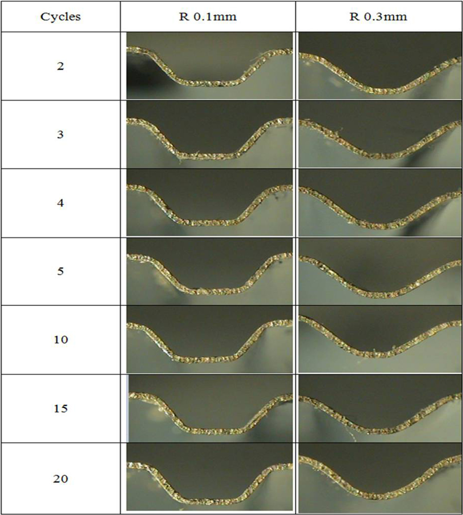
Section view according to sine dynamic load for different cycle numbers and die radii (punch load: 50–100 kN, frequency: 0.5 Hz).
Figure 13 shows the results of the comparison of the thinning of the bipolar plates with a variation in the load cycles under the existing static load and dynamic load with the square wave, which showed the maximum depth, as seen in Figure 7. As seen in this figure, the value of the thinning in the bipolar plate decreased when the radius of the channel roundness increased from 0.1 to 0.3 mm. In addition, regardless of the roundness of the microchannel and the number of load cycles, the thinning was almost constant. This result means that the dynamic load contributes to improving the formability by reducing the springback without additional metal flow.
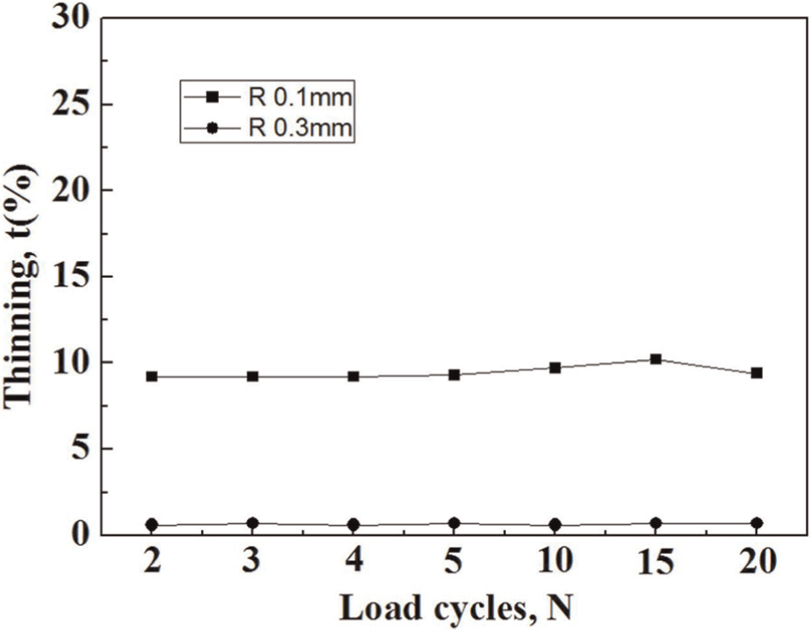
Relations between the cycle number (square 50–100 kN) and thinning of stainless steel.
Conclusion
The following results were obtained by the experiments performed to evaluate the effect of the dynamic load on the formability of a stainless steel thin plate stamped with a serpentine shape.
In the case of the dynamic stamping process, the forming depth of the bipolar plate with the roundness of 0.1 and 0.3 mm increased, when the number of cycles increased, and the process, in particular, contributed to improving the forming depth of the bipolar plate with the channel roundness of 0.3 mm. However, the increase in the depth of the plate stamped under the repetitive dynamic load over five cycles was marginal.
From the comparison of the forming depths of the plates fabricated by the static and dynamic stamping processes with a square wave, the forming depth was commonly improved up to 7%.
The thinning was improved up to 28% by using the stamping process with the dynamic load of the sine wave. However, the thinning of the bipolar plate with the channel roundness of 0.3 mm showed little difference.
The thinning of the bipolar plate was almost constant, regardless of the channel roundness and number of loading cycles. Therefore, the forming depth can be improved by the dynamic load without the change in the thinning.
Footnotes
Funding
This research was supported by the National Research Foundation (NRF) of Korea grant funded by the Korea government (MEST) (grant no. 2012-0000172) and by the NRF of Korea grant funded by the Korea government (MEST) through GCRC-SOP (grant no. 2012-0001204).