
Abstract
A titanium alloy is selected as an ideal material for a fuel-cell bipolar plate because it has a low density and, like aluminium, exhibits excellent corrosion resistance due to an insulating oxide film. Microchannelled bipolar plates are fabricated using a 25-ton material-testing machine by varying the parameters of the static and dynamic loads (type of load wave, punch load, number of cycles) and the die curvature in order to evaluate the formability. The bipolar plate formed by dynamic-load stamping (square wave of 0.5 Hz, 32 load cycles, punch load of 90 kN) with die curvature of 0.3 mm resulted in 13.0% deeper channels compared to static-load stamping of 90 kN. Moreover, in the case of 0.1 mm die curvature, the bipolar plate formed by square-wave dynamic-load stamping had 22.7% deeper channels, compared to static-load stamping. Dynamic-load stamping with die curvatures of 0.1 and 0.3 mm shows a channel depth of 0.251 and 0.353 mm, respectively. Compared to die curvature of 0.1 mm, 0.3 mm die curvature resulted in channels that are deeper by 28.9%.
Introduction
Fuel cells are a new type of power-generating technology with high efficiency. They do not produce environmental problems since they do not involve combustion like other power-generating technologies. Proton exchange membrane fuel cells (PEMFCs) are polyelectrolyte fuel cells that make use of hydrogen and oxygen as fuel, with the advantages of high efficiency, high current density, low operating temperature, and high system durability. They are widely applied in fields such as transportation, power generation, and mobile-phone devices. 1,2
PEMFCs are receiving much attention as an environment-friendly approach to reducing automobile emissions. However, the difficulty in the commercialization of current PEMFCs is in terms of price compared to gasoline engines. Therefore, studies on weight and associated cost reduction of bipolar plates, which account for more than half of the stack price in PEMFC systems, are being conducted. 3,4
A bipolar plate is attached to both sides of a membrane electrode assembly (MEA), which contains functionality channels through which the electricity generating fuel and oxygen move. The bipolar plate is an important component that fulfils further functions in the operation of a PEMFC, such as current collection, heat removal inside the stack, and prevention of leakage of the reactants. The materials used for bipolar plate manufacturing must have excellent properties with regard to electrical and thermal conductivity, corrosion resistance, low specific gravity, low material cost, and low manufacturing cost. 5 The forming process of a metallic bipolar plate includes milling, 6 stamping, 7 –9 rubber forming, 10,11 hydroforming, 7 etching, 12 Lithography Galvanik Abformung (LIGA)-electroforming, 13 die casting, 14 –16 and semi-solid forging. 17 –19 Among these processes, machining and shearing of the bipolar metal plates require a large amount of time and, therefore, involve excessive manufacturing costs compared to the low material cost, which represents a major difficulty in reducing prices. Many studies have been conducted with respect to the stamping process of fuel-cell bipolar plates for lowering the manufacturing cost and time through mass production. However, the shortcomings of this method include a reduced performance of the fuel cells due to the occurrence of springback because of elastic recovery and forming limitations, thereby resulting in channels that cannot be formed sufficiently precisely according to the design dimensions. 7,20 Turan et al. 8 fabricated stainless steel bipolar plates by static-load stamping and addressed the formability and surface topography of the bipolar plates. Kwon and Kang 21 fabricated Al5052 bipolar plates by static-load stamping and investigated their formability. However, there are no studies until now on the production of bipolar plates of titanium material using dynamic-load stamping. In this study, to reduce the forming limitations during the stamping process, we present a method of forming titanium bipolar plates by using dynamic-load stamping. The bipolar plates fabricated this way could possibly substitute graphite-based ones. Dynamic-load stamping can be applied using various types of loads like square waves, ramp waves, and sine waves during the forming process. In order to overcome the forming limitations of the static-load stamping process and to form more precise channels, a forming experiment was conducted using 0.1-mm thick titanium material and two types of die roundness, which greatly affects the performance. Through these experiments, the best suited types of dynamic forming load and the number of cycles were derived, and the formability was evaluated by a comparison with bipolar plates that were fabricated by the static-load stamping process.
Experiment
Experimental apparatus
A dynamical material-testing system (MTS) with a rated load of 25 tons was used for conducting the experiments. The MTS equipment is appropriate for such dynamic-load stamping experiments that require precise loads since the microadjustment of the rate and magnitude of the load is easy, and various frequencies in the form of sine waves, square waves, and ramp waves can be realized. The load and displacement were measured using a load cell and strain metre attached to the pressing equipment during the stamping, respectively. Figure 1 shows the experimental equipment used to manufacture the titanium-based bipolar plates under dynamic load. The experimental equipment is composed of seven components including the load cell, upper die, lower die, and upper and lower core dies for the two types of channels, namely part-I (die curvature R = 0.1 mm) and part-II (die curvature R = 0.3 mm). To facilitate the exchange of the stamping punch and die, a channel-core die was used employing the internal insertion method. The die structure is associated with the die curvature values of 0.1 and 0.3 mm, labelled channel part-I and channel part-II, respectively.
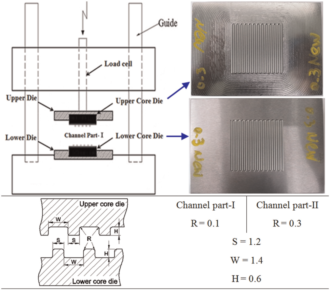
Schematic diagram of experiment equipment and dimension of stamping die (unit: mm).
Experimental conditions and procedures
When the upper punch presses against the lower die, the titanium plate passes through the elastic region and, subsequently, is subject to plastic deformation. The plastically deforming material fills the lower die cavity, and the channels in the thin plates are formed by the continuous application of dynamic load in the form of a sine wave, square wave, or ramp wave for various numbers of cycles.
The material used in the experiments was a titanium-alloy plate with a thickness of 0.1 mm obtained by machining a blank which is 55 mm in width (rolling direction) and 55 mm in length. Table 1 shows the composition of the titanium alloy (ASTM Grade 5) of the experimental specimen. Because titanium plates are durable and have high strength, they are usually used as structural material in areas such as aviation and automotive. Titanium material is expensive compared to aluminium and stainless steel, but it has a low density and, like aluminium, exhibits excellent corrosion resistance due to an insulating oxide film. It also has the advantage of being able to form diffusion bonds with itself allowing complicated flow-field designs to be constructed by overlaying several layers. By this way, it is possible to greatly improve the performance of fuel cells.
The chemical composition of the titanium alloy (ASTM Grade 5) (wt%).

Table 2 shows the conditions of the static- and dynamic-load stamping experiments. The experimental parameters include the type of load, punch load, rate and frequency, number of cycles, and die curvature. For static-load stamping, seven loads in the range of 50–110 kN were applied in steps of 10 kN.
The conditions of stamping experiments.
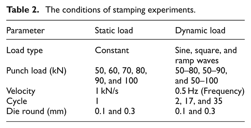
The dynamic-load stamping was applied in the form of sine, ramp, and square waves (at a frequency of 0.5 Hz) for different numbers of 2, 17, and 32 cycles applied for each loading to ensure that the bipolar plate continues to be formed even under the minimum punch load of 50 kN during one cycle. The stamping experiments were conducted six times under static and dynamic loads to obtain average values of sufficient accuracy.
In order to examine the deformation behaviour of the material and to check for the presence of fractures after the experiment, the manufactured bipolar plate was wire cut and the appearance of the channels in the formed material was observed using a digital microscope.
Figure 2 shows the results of forming-depth measurements in the horizontal channel cross section A-A of the bipolar plate. According to its definition, the forming rate is the criteria used to evaluate the formability of the channels by considering how much of the die height (0.6 mm) has been formed. The thinning was measured to evaluate the crack possibility. The term thinning in this study refers to the magnitude in thickness change at the edge of the channel after forming. If the thinning is big, a crack is easily induced. The channel depth and thinning were measured using image analysis of optical microscopy.
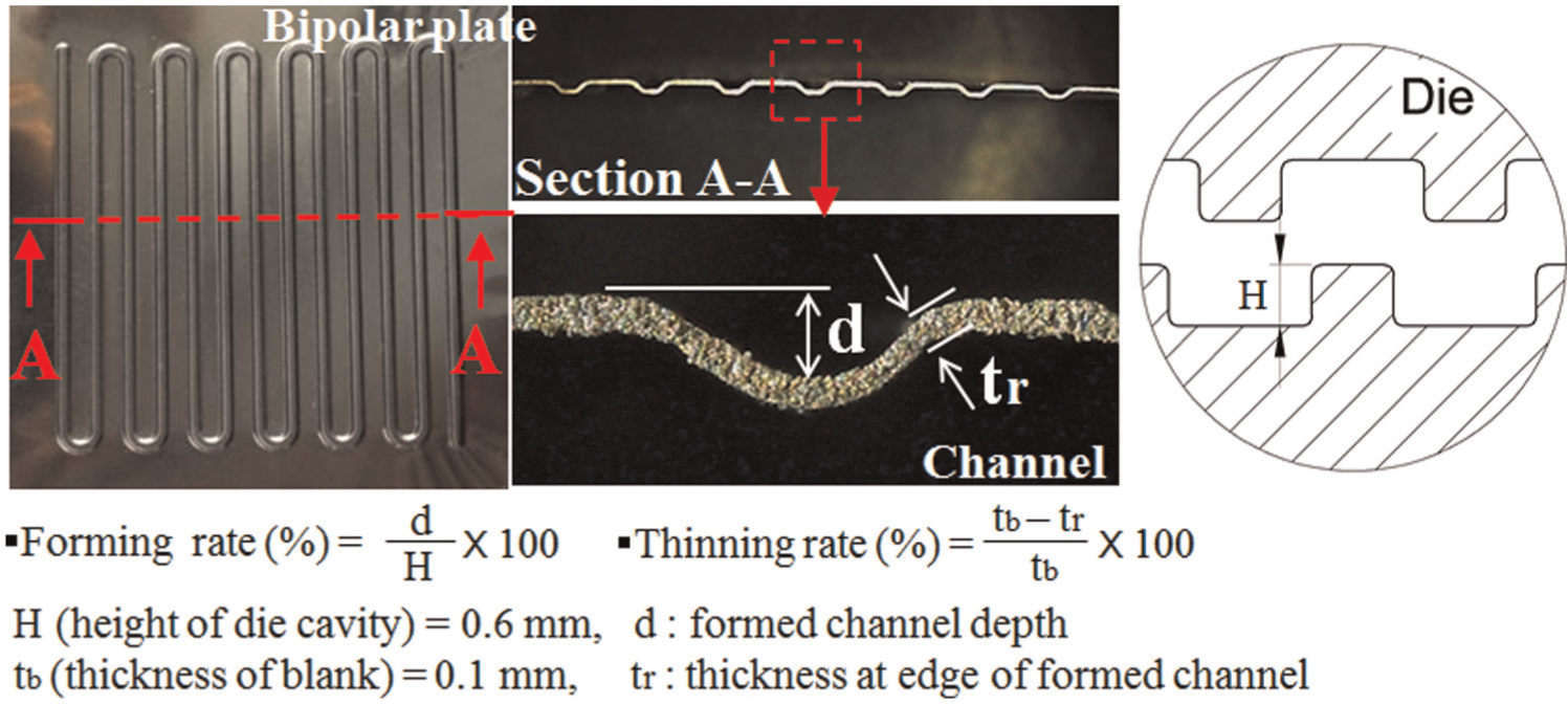
The definition of forming and thinning rates.
Experimental results
Static-load stamping
After the tests were performed under the conditions listed in Table 2, the effect of the different process conditions on die filling is investigated. In fact, different forming parameters resulted in different filling characteristics.
Figure 3 shows the forming results of the bipolar plate in dependence of the punch load and die curvature in the static-load stamping experiment under the conditions shown in Table 2. A complete filling is reflected in that the bipolar-plate channels have been formed well with a depth of more than 0.3 mm without defects. Incomplete filling is characterized by the fact that the bipolar-plate channels could not be properly formed due to an insufficient punch load. In addition, resulting cracks emanating from the round area of the bipolar-plate channels imply that the material is not able to endure the punch load.
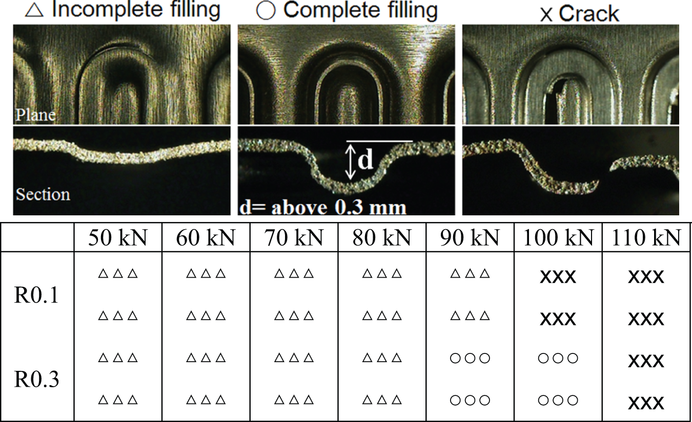
The facture diagrams at different static loads of punch and die rounds.
In the case of forming with a load of 50–90 kN and 0.1 mm die curvature, incomplete filling occurred in the bipolar plate. If forming was performed with 0.3 mm die curvature, incomplete filling took place at a load of less than 90 kN, but complete filling occurred at loads of 90 and 100 kN. In the case of 100 kN, no cracks were present in the bipolar plate with a die curvature of 0.3 mm, but a crack was observed in the round area of the channel of the bipolar plate for a die curvature of 0.1 mm. These results show that the channels can be properly formed if the titanium plate is pressed with a punch load of at least 100 kN. Based on the incomplete filling of the sheet metal in the die cavity, it was decided to use dynamic loading in the form of sine, square, and ramp waves at loads of 80, 90, and 100 kN during the bipolar plate forming process.
Figure 4 shows the depth and thinning of the bipolar-plate channels in dependence of the punch load after forming using the static-load stamping method. It was observed that the depth of the channel uniformly increased by increasing the punch load. At a punch load of 90 kN, the channel depth with a die curvature of 0.1 mm was 0.194 mm. For a die curvature of 0.3 mm, the corresponding channel depth was 0.307 mm. In addition, the channel depth for a die curvature of 0.3 mm was deeper by 36.8%, compared to the channel depth when using a die curvature of 0.1 mm. The die curvature of 0.3 mm had a higher precision and formability in the case of a punch load of 100 kN. In the case of die curvature of 0.3 mm, the punch load of 100 kN resulted in a better filling rate by at most 4.4% compared to the 90 kN punch load. A crack occurred when forming was performed with a load of 110 kN, and it was observed that the channels were not completely formed in the vicinity of the crack. Accordingly, the channels of bipolar plate were formed in dependence of the number of cycles by setting the maximum punch load to 100 kN when performing dynamic-load stamping.
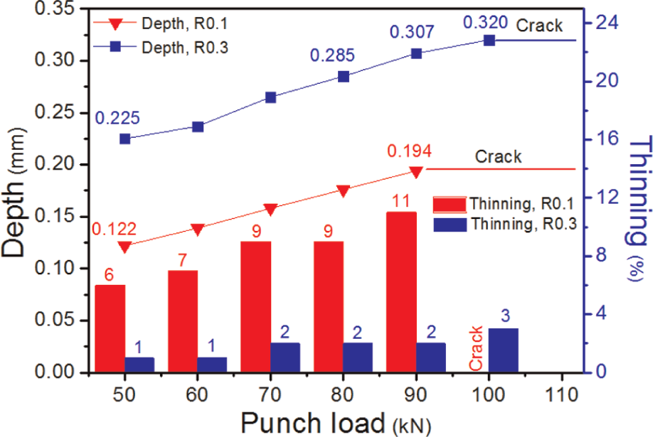
Depth and thinning of bipolar-plate channels formed at different static loads of punch.
When the die curvature was 0.1 mm, the thinning rate of the bipolar-plate channel formed by a load of 80 kN was 9%. However, when the die curvature was 0.3 mm, the thinning rate was 2%. In the case of 90 kN, the thinning rates for 0.1 and 0.3 mm die curvatures were 11% and 2%, respectively. For 100 kN, a crack occurred when the die curvature was 0.1 mm. When the die curvature was 0.3 mm, the thinning rate was 3%. As the punch load increased, the thinning rate increased as well. A significantly greater thinning rate was observed in the case of 0.1 mm die curvature compared to 0.3 mm. This seems to be caused by the fact that the die with curvature of 0.1 mm has a sharper corner compared to the die with curvature of 0.3 mm. Therefore, the die with curvature of 0.1 mm would allow for an increased thinning rate since a higher direct load is present in the curved area of the die during forming.
Dynamic-load stamping
Figure 5 shows the changes over time in the dynamic-load stamping experiment under the conditions listed in Table 2. The frequency of the dynamic load is 0.5 Hz (= 0.5 cycles/s), so it takes 2 s for one cycle of punch load to be applied in the forming process. In the case of 32 cycles, the punch load is applied for 64 s, and the forming process needs this time to be completed. To apply a sufficient force of 100 kN in the case of static-load stamping at a rate of 1 kN/s, 100 s is needed. Compared to 100 s needed in the case of static-load stamping to form a metal bipolar plate, it takes only 64 s in the case of dynamic-load stamping for 32 cycles. This means that dynamic-load stamping allows for deeper and more precise forming in a very short period of time, compared to static-load stamping.
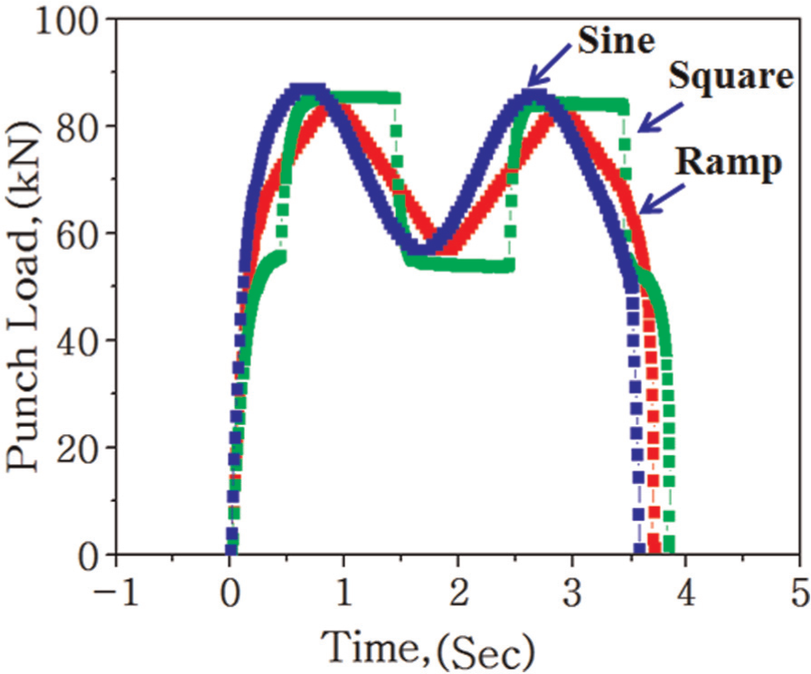
The load–time curves with different types of dynamic load.
Figure 6 shows the forming results of the bipolar-plate channels using different numbers of cycles of dynamic stamping with sine, square, and ramp wave-type loads. In the case of a sine wave, when the punch load was varied from 50 to 100 kN and the cycle number was 32, a crack occurred at the two different investigated die curvatures. In addition, when a crack occurred in the case of static-load stamping, since a punch load of 100 kN could not be endured, the bipolar plate formed by applying dynamic load in the form of a sine wave did not show any cracks for the first 17 cycles.
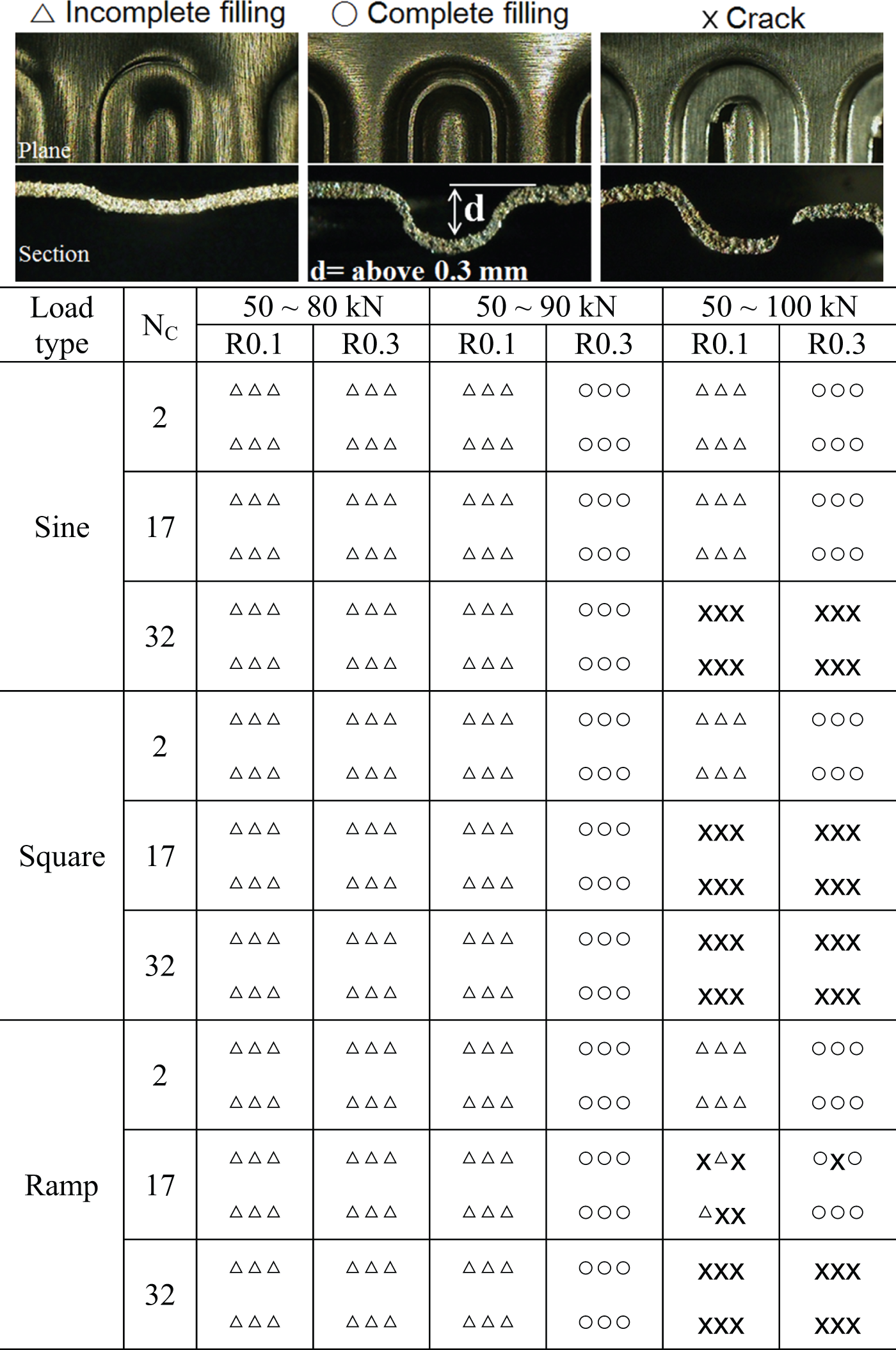
The facture diagrams at different waves of dynamic load and die rounds.
In the case of a square wave, when die curvature was either 0.1 or 0.3 mm and the punch load was varied between 50 and 100 kN, cracks occurred at the sharp corners at cycles 17 and 32, respectively. These results originate from the sudden load changes in the case of a square wave, which caused the occurrence of cracks in areas with a large curvature. Therefore, it is understood that square waves are not appropriate for forming bipolar plates with a die curvature of 0.1 mm. The punch-load rate of the bipolar plate is fast in the case of static-load stamping, which causes rapidly increasing deformations of the bipolar plates. Because of this, the flow stress that induces plastic deformation likewise tends to increase. It is suggested that subsequently, the elongation rate reduces, thereby inducing more cracks in the case of static-load stamping (compared to dynamic-load stamping). Furthermore, it is also suggested that the cracks occurring more quickly in the case of static-load stamping are related to the increased friction between the punch, which applies the load onto the specimen, and the die since in the static-load stamping process the punch load increases rapidly up to the load set point. It is considered that the forming rate in dynamic-load stamping is higher because of reduced springback effects upon repeated loading. In the case of a ramp wave, in which the change between maximum and minimum punch loads is greater than for the sine wave but smaller than for the square wave, a crack occurred at cycles 17 and 32 for the die curvature of 0.1 mm. For the die curvature of 0.3 mm, a crack occurred at cycle 32. These results were obtained for a punch load in the range of 50–100 kN.
Figure 7 shows the depth of the formed channels according to the number of cycles for different types of waves of the dynamic load (50–90 kN). It can be observed that the channel depth increases as the number of cycles and the die curvature increases. For a sine wave, when the die curvature was 0.3 mm, the channel depths formed after 32 and 2 cycles were 0.349 and 0.309 mm, respectively. The difference in channel depth for the two different cycle numbers was 0.04 mm, so the channel formed by applying 32 cycles was deeper by 11.5%. This shows that the channels of the bipolar plate are formed more precisely and more deeply with increase in the number of cycles. Furthermore, there is a proportional relationship of the forming-depth and the punch time. For a square-type wave, for 32 cycles and a die curvature of 0.3 mm, it was possible to form channel depths of up to 0.353 mm with a maximum forming rate of 58.8%. In the case of a ramp wave, again for a die curvature of 0.3 mm, the channel depth formed after 32 cycles was 0.036 mm deeper than the one obtained by applying 2 cycles only. This result corresponds to an increase in channel depth of at most 11.5%. After 32 cycles, a maximum depth of 0.345 mm with a maximum forming rate of 57.5% was observed for a die curvature of 0.3 mm.
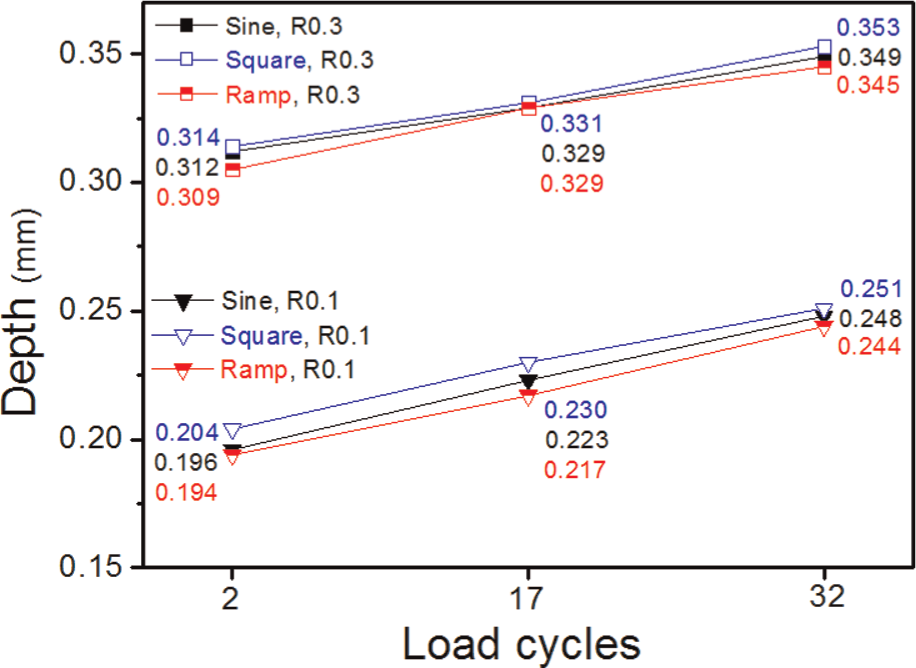
Depth of channels formed by different waves of dynamic load (50–90 kN).
Comparison between static and dynamic loads
Figure 8 shows the results of the channel depths and thinning rates of the bipolar plates formed by either static or dynamic load. The bipolar plate was formed six times under the same load condition, and then, the formed channel depths were measured to obtain average values of sufficient accuracy, which are shown along with the maximum and minimum values.
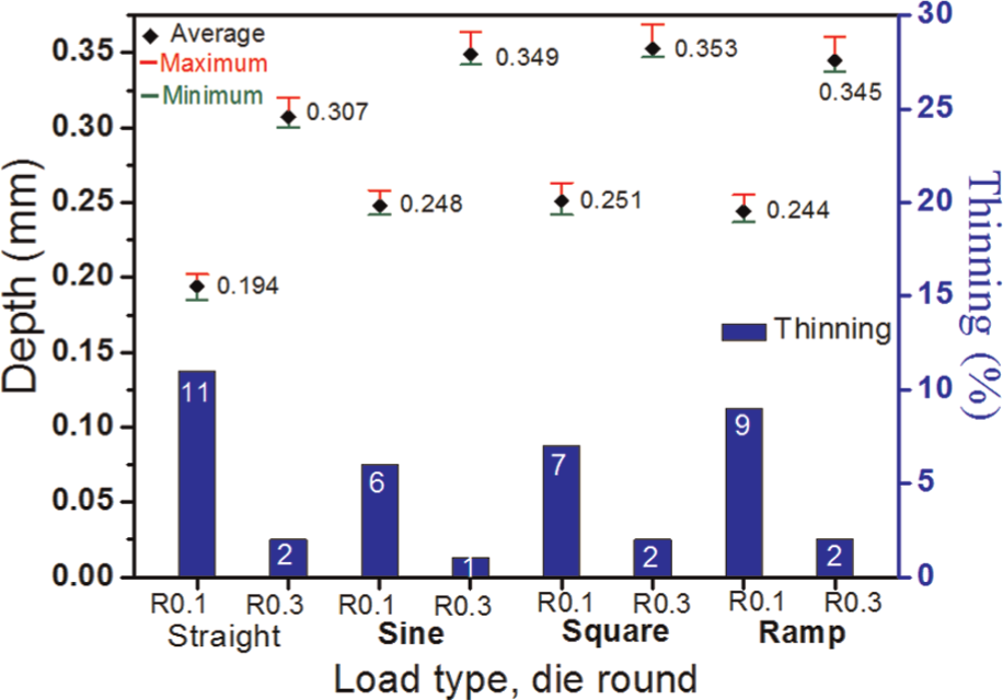
The comparison of channel depth and thinning rate between dynamic load of 50–90 kN (32 cycles) and static load of 90 kN (1 cycle).
Among the bipolar plates formed by dynamic loads, the bipolar plates formed by square-wave load showed the deepest channel. In the case of a die curvature of 0.1 mm, the channel depth formed by static-load stamping was 0.194 mm. On the other hand, forming was possible until a channel depth of 0.251 mm by applying 32 cycles of square-wave dynamic load. The difference in channel depth of the bipolar plate between static- and dynamic-load stamping was 0.057 mm, corresponding to 23.7% deeper forming by applying dynamic-load stamping. In the case of the die curvature of 0.3 mm, the channel depth of the bipolar plate formed by static-load stamping was 0.307 mm. Furthermore, it was possible to form channels with a depth of up to 0.353 mm after 32 cycles of a square-wave dynamic load. The difference in channel depth after 32 cycles using a square-wave dynamic load and static-load stamping was 0.046 mm. Compared to static-load stamping, dynamic-load stamping resulted in channels that are deeper by 13.0%. This means that dynamic-load stamping allows for a more precise and deeper forming of the channels, compared to static-load stamping, since dynamic forming is performed by the repeated application of a force during the elastic recovery after a complete forming cycle.
As shown in Figure 8, for a die curvature of 0.1 mm, the thinning rates of the bipolar plates formed under static and square-wave dynamic stamping for a load of 90 kN were 11% and 7%, respectively. The thinning rates of the bipolar plates formed under the same load of 90 kN applying sine and ramp-type waves were 6% and 9%, respectively. In the case of 0.3 mm die curvature, the thinning rates of the plates formed by the two different methods were all less than 5%, which is very low compared to the results using a die curvature of 0.1 mm. It is considered that the thinning rate increased due to the higher load in the curved area of the die curvature of 0.1 mm, compared to the die curvature of 0.3 mm.
Conclusion
Titanium bipolar plates with channels for fuel-cell applications were manufactured using dynamic-load stamping. The conclusion drawn from the forming experiments employing various parameters are as follows:
The forming of metal bipolar plates by stamping titanium plate with a thickness of 0.1 mm needs a punch load of at least 100 kN.
In the case of applying a punch load of 90 kN and a die curvature of 0.3 mm, the bipolar plate formed by dynamic-load stamping applying a square wave of 0.5 Hz and N = 32 load cycles resulted in 13.0% deeper channels compared to static-load stamping. Moreover, in the case of 0.1 mm die curvature, the bipolar plate formed by dynamic-load stamping had 22.7% deeper channels, again compared to static-load stamping.
In the case of forming by dynamic-load stamping, it was observed that a greater punch pressure and a larger number of cycles were effective in achieving large channel depths in the bipolar plates. As the time of the punch load increased, the channels of the bipolar plate were formed with higher precision, in direct proportional relationship.
In the case of a die curvature of 0.1 mm, dynamic-load stamping applying a square-wave-type punch load of 90 kN showed a maximum depth of 0.251 mm and a maximum forming rate of 41.8% after 32 forming cycles. On the other hand, the bipolar plate formed with a die curvature of 0.3 mm showed a maximum depth of 0.353 mm and a maximum formability of 58.8%.
The reason for the rather low forming rate is the difficulty to form appropriate channel patterns of a bipolar plate using thin sheet materials, in particular, in the case of a small die clearance of 0.1 mm, in contrast to other, more conventional types of plate forming. In addition, because of the very narrow clearance gap, it is considered that the low forming rate may also be related to significant springback effects. It is suggested that there is a need for future studies regarding the effect of changes in the clearance gap.
Footnotes
Declaration of conflicting interests
The authors declare that there is no conflict of interest.
Funding
This work was supported by the National Research Foundation of Korea (NRF) Grant funded by the Korean Government (No. 2013R1A1A2062759), by Human Resources Development of the Korea Institute of Energy Technology Evaluation and Planning (KETEP) Grant funded by the Korea Government and Ministry of Knowledge Economy (No. 20104010100540) and also by the National Research Foundation of Korea (KRF) Grant funded by the Korea Government (MISP) through GCRC-SOP (No. 2012-0001204).