
Abstract
The rubber pad forming process has been used to fabricate metallic bipolar plates from aluminum 1050 alloy for use in a proton-exchange membrane fuel cell. The plates were fabricated using a 200 ton hydraulic press and the effects of the process parameters of the rubber pad forming process (plate thickness, punch speed, press pressure, rubber thickness and rubber hardness) on the forming depth and thinning were evaluated.
Introduction
There is increasing interest in the development of alternative energy sources; partially driven by global-warming concerns. Fuel cells are one such energy source and they are receiving particular attention since they are highly efficient, pollution-free energy sources and have the advantages of low noise and relatively free site selection. In addition, their feed fuels such as hydrogen, natural gas and methanol1,2 are readily available. The proton-exchange membrane fuel cell (PEMFC) is attracting attention for use as an eco-friendly alternative power supply for vehicles that would result in reduced exhaust fume emissions. However, present PEMFCs have problems in terms of their weight and cost, which are preventing their commercialization. The bipolar plate, which is one of the core components of the PEMFC, accounts for 60–80% and 30–45% of the total weight and cost of the fuel cell, respectively.3,4 Plates with functional channels to move the hydrogen and oxygen are assembled at both sides of the membrane electrode assembly. The bipolar plate also plays significant roles in collecting the current, removing heat in the stack and preventing the leakage of reactants. Therefore, the important characteristics of the bipolar plate are its heat conductivity, its anti-corrosion specific heat, and the cost and processing cost of the material. 5
Currently, the most widely used material for bipolar plates is graphite; it displays excellent anti-corrosion and conductivity properties. The graphite plate is processed by conventional methods such as lathing and milling, which are high-cost processes with low productivity levels that are a result of the material being brittle and having poor gas permeability that make it difficult to machine.
Various studies have been performed to find a substitute material for the bipolar plate: carbon composites, titanium, stainless steel and aluminum have been widely considered. Stainless steel has the advantages of good machining characteristics, a low cost, excellent mechanical properties and high current conductivity; however, the degradation of the electrolyte membrane and the creation of an oxide film on the surface of the bipolar plate due to corrosion rapidly reduce the current conductivity levels. Therefore, aluminum alloys are of particular interest due to their high anti-corrosion properties, low weight (one-third that of stainless steel and one-half that of titanium), low electrical resistivity (1/25th that of stainless steel) and high heat conductivity (14 times that of stainless steel). In this paper we carry out studies on bipolar plates made of aluminum 1050 (Al 1050), the characteristics of which are better than any other aluminum alloys for such plates.6,7
CNC milling, stamping/embossing, hydroforming, extrusion, etching and LIGA-electroforming have all been used to manufacture bipolar plates.8−15 While rubber pad forming of stainless steel to fabricate the bipolar plates has been reported in the literature, 16 that study was confined to the geometric dimensions of the stamping die, and did not consider the effects of process variables. Thus, the evaluation of the formability in terms of pressure, velocity and specifications of the rubber pad was not performed in that study. Rubber pad forming is a process that creates an improved dimensional accuracy through the use of a homogeneous load distribution that is obtained by wrapping the convex part of the punch in a rubber pad on the die during the forming process.
Browne and Battikha 17 studied the rubber pad forming process as a potential manufacturing process for aircraft wings. The performance of the product fabricated by this process was reported and processing parameters were optimized to reduce defects. Sala 18 conducted a study on the optimization of rubber pad forming on the basis of both simulations and experiments and Ramezani et al. 19 predicted the behavior of friction during rubber pad forming.
Despite its many advantages this forming process has only found limited application in the manufacture of large products such as aircraft wings. In this study, we investigate the effects of the processing parameters of rubber pad forming on the formability of bipolar plates.
Experimental method
Figure 1 shows a schematic diagram of the die and photographs of the equipment used in this study. The experimental system consisted of a joint to connect the upper die with the press, an upper die equipped with a convex punch for forming the bipolar plate and a lower die with a rubber pad fixed to it, which can be freely deformed with an arbitrary shape. A 200 ton hydraulic press was used.
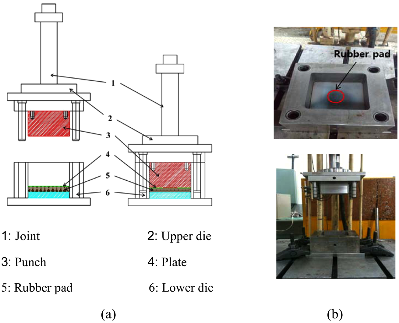
(a) A schematic diagram of the stamping die and (b) photographs of the stamping die.
Figure 2 illustrates the rubber pad forming process considered in this study. As can be seen in Figure 2(a), the rubber pad and the sheet metal plate are pressed together by the punch; the repulsive force of the deformed rubber is loaded at the plate, and can contribute to improving formability. Figure 2(b) shows the dimensions of the bipolar plate sample used in this study.

Schematic diagram of the rubber pad forming process (a) rubber pad forming and (b) the plate sample.
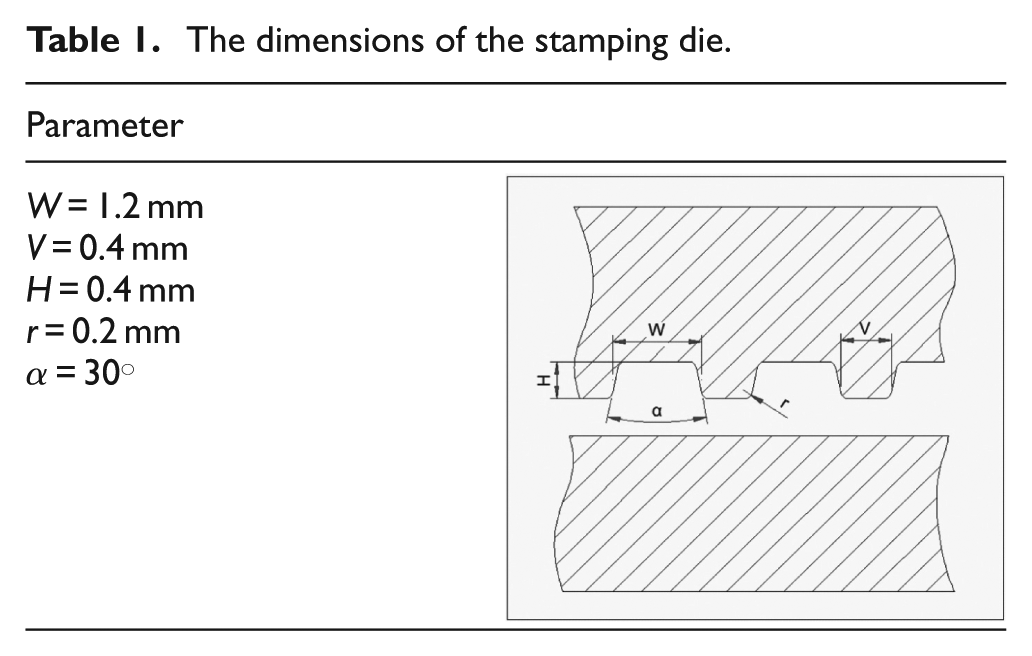
The main dimensions of the upper die are listed in Table 1. As shown in the table, the microchannel width was 1.2 mm, the rib width was 0.4 mm, the microchannel depth was 0.4 mm, the roundness was 0.2 mm and the draft angle was 30°. In this study, the bipolar plate manufactured using this tool had a microchannel width of 0.8 mm, a microchannel depth of 0.4 mm, a roundness of 0.2 mm and a draft angle of 30°.
The dimensions of the stamping die.
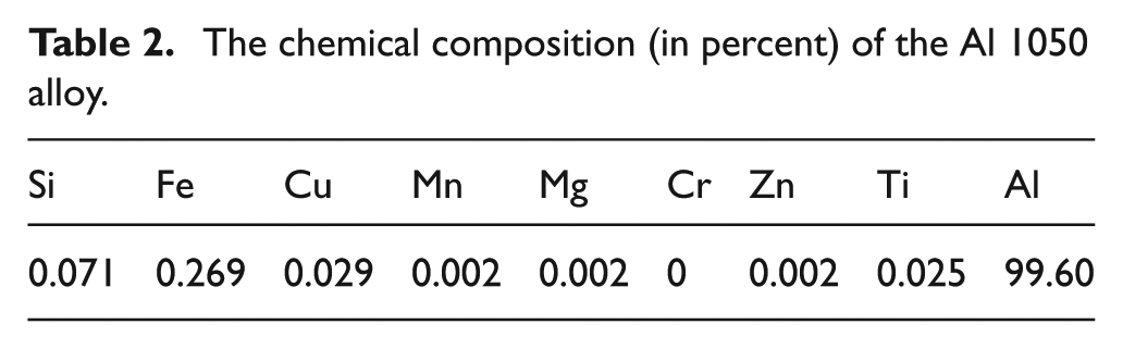
The chemical composition of the Al 1050 alloy used in this study is listed in Table 2. The plate, with a thickness value of either 0.2 or 0.3 mm and length and width of 100 mm, was processed in the rolling direction. The mechanical properties of the material are listed in Table 3.
The chemical composition (in percent) of the Al 1050 alloy.
Physical properties of the Al 1050 alloy.
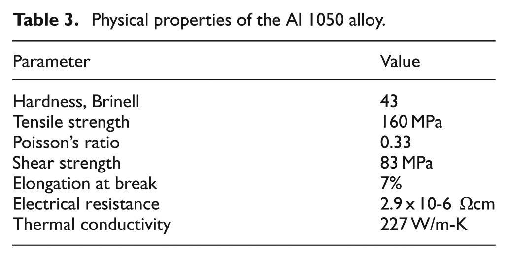
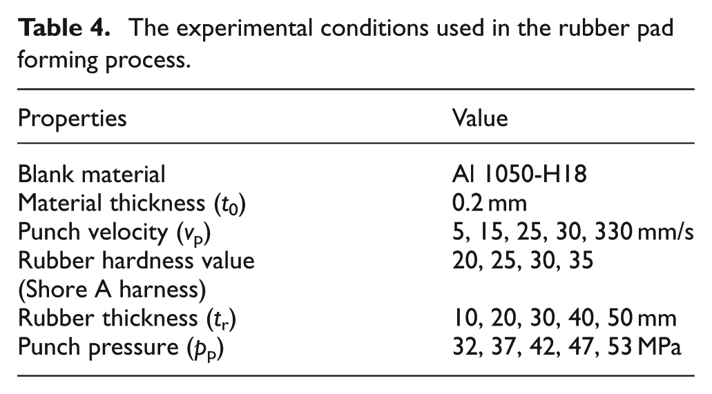
Table 4 lists the experimental conditions used in the rubber pad forming process. The experimental variables used to evaluate the formability were the punch velocity and pressure, rubber hardness and thickness, and material thickness. The velocity was 5, 15, 25, 30 or 330 mm/s. The value of 30 mm/s is the maximum velocity in the low-speed section of the utilized press machine, and 330 mm/s is the maximum velocity in the high-speed section of the machine. However, it is very difficult to control the velocity in the high-speed section due to load inertia effects. Therefore, experiments were performed at velocities between 5 and 30 mm/s and at 330 mm/s. The pressure was 32, 37, 42, 47 and 53 MPa. The value of 53 MPa was the maximum pressure obtained in a preliminary experiment to find the critical value that could be used without causing forming defects. The hardness of the rubber pads were Shore A harness values of 20, 25, 30 and 35 and the thickness values were 10, 20, 30, 40 and 50 mm; tensile tests were performed using an Autograph AG-X Universal Testing Machine to obtain the stress–strain curves of rubber pads with different hardness values. The obtained stress–strain curves are shown in Figure 3. After the experiments, the microchannels of the bipolar plates were analyzed using an optical microscope to investigate their deformation and defects, and the results were quantified in terms of the depth and thinning values.
The experimental conditions used in the rubber pad forming process.
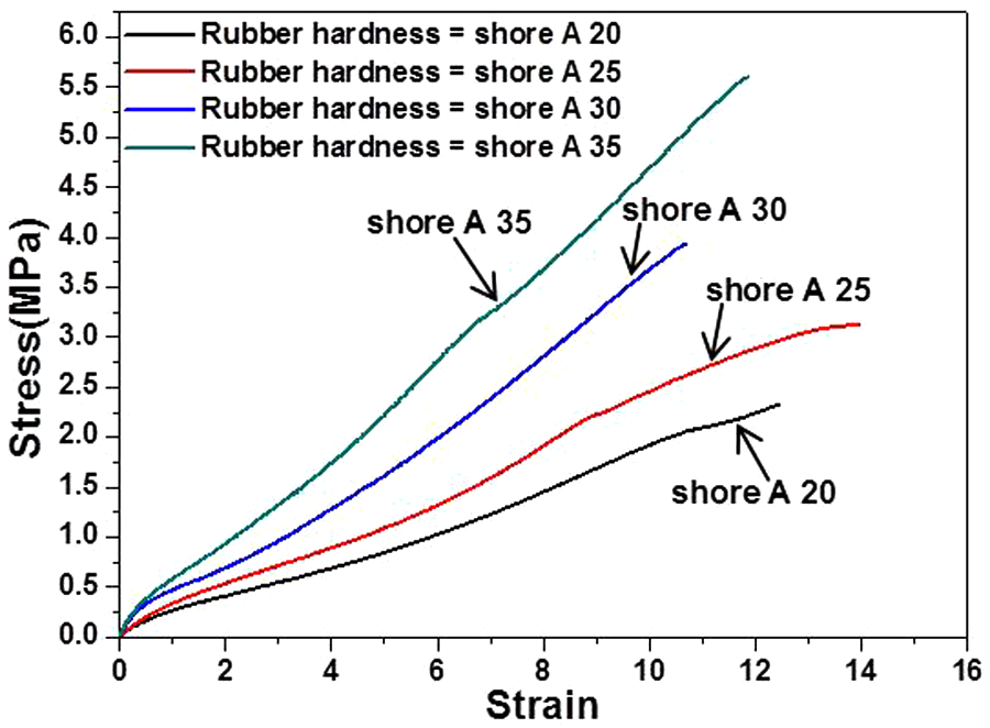
Stress–strain curve for rubber samples with Shore A hardness levels of 20, 25, 30 and 35.
Results and discussion
Forming depth
Figure 4 shows the measuring position and criteria used to evaluate the stamping depth and forming limit. As shown in Figure 4(a), in order to evaluate the formability on the basis of the forming depth, the bipolar plates were cut in the horizontal and vertical directions, and the cross-section was analyzed using a PAM microscope (Sometech, Seoul, Korea) that has a resolution of 1/1000 mm. Figure 4(b) shows the definition and criteria for the forming limit depth rate (
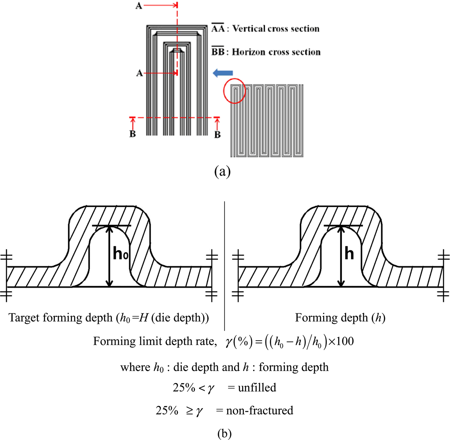
(a) Measuring position and (b) criteria for evaluating the stamping depth and forming limit.
Figure 5 shows the forming depths for the 0.2 and 0.3 mm thick aluminum sheets as a function of the depth of the rubber pad. A punch pressure of 53 MPa and a punch speed of 330 mm/s were used in these experiments. The thickness values of the pad were 10, 20, 30, 40 and 50 mm and the Shore A harness value was varied. As shown in Figure 5, the maximum horizontal and vertical forming depths of the 0.2 mm thick bipolar plate were 0.477 and 0.483 mm, respectively, for rubber with a Shore A hardness value of 20 and a thickness of 30 mm. These values show that the material has excellent formability properties since the rubber pad used as the lower die could be deformed to an arbitrary shape, unlike dies used in conventional process. In addition the reactive force created by the deformation was active on the plate. Meanwhile, as shown in Figure 5(b), for both the 0.2 and 0.3 mm thick aluminum alloy plates the thickness of the rubber has a relatively strong effect on the filling depth. However, in Figures 5(a), (c) and (d), the effect of the thickness of the rubber on the forming depth is very small; in fact in Figure 5(d), it almost has no effect. In spite of this phenomenon, each rubber pad has the characteristic range of the forming depth. Therefore, it is concluded that the hardness and thickness of the rubber pad can be customized to manufacture a bipolar plate with a specific forming depth using the rubber pad forming process.
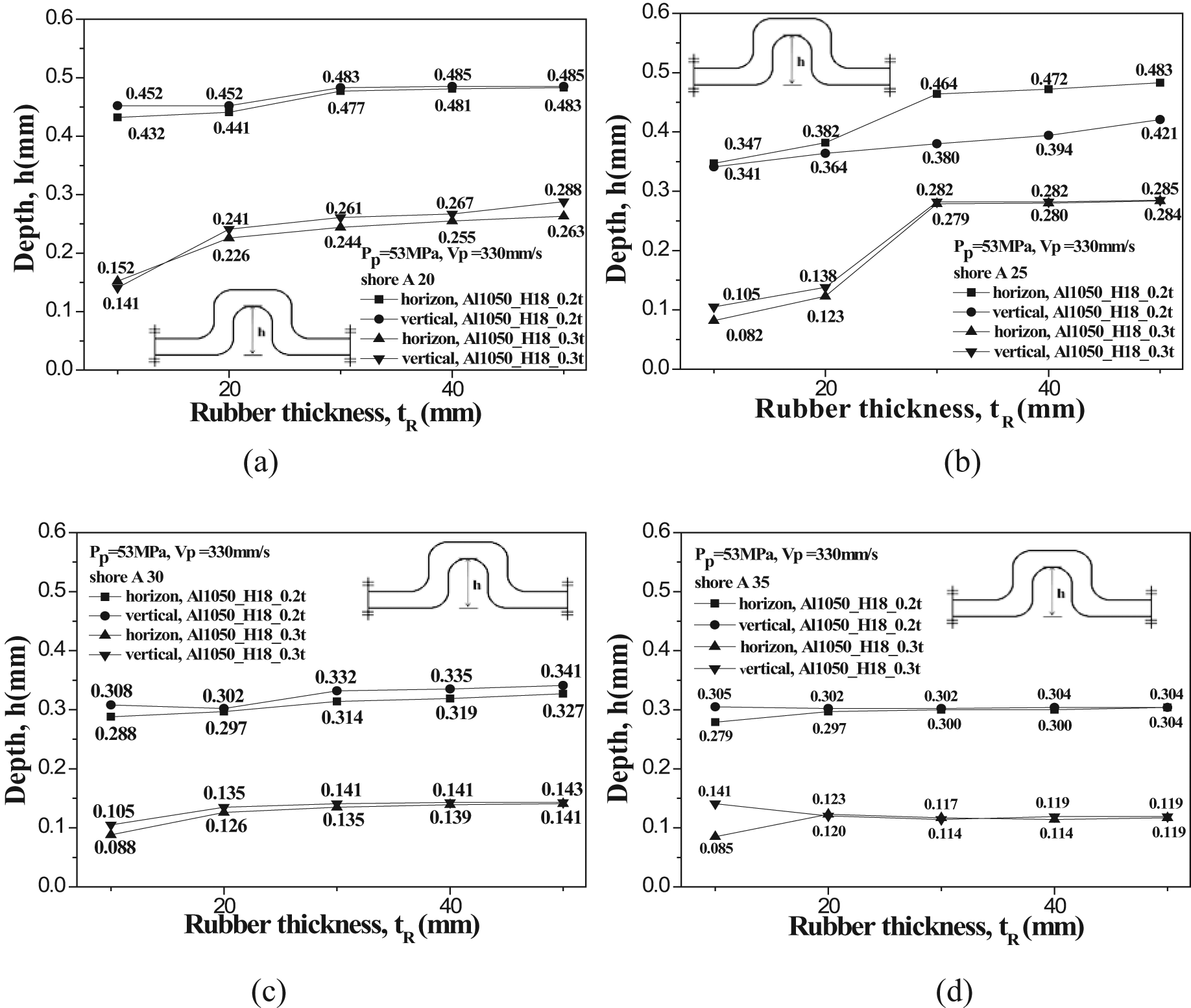
Stamping depth as a function of rubber thicknesses for Shore A harness values of (a) 20, (b) 25, (c) 30 and (d) 35.
Figure 6 shows the forming depth for different rubber hardness values and varying plate thicknesses. A punch pressure of 53 MPa and punch speed of 330 mm/s were used in these experiments. The thickness of the pad was 30 mm, to achieve the maximum forming depth. As can be seen in this figure, the depth is inversely proportional to the rubber hardness value regardless of the direction. This is because a relatively high reactive force is created that is proportional to the deformation of the rubber pad and is inversely proportion to the hardness. This force enables the cavity in the die to be filled with deformed rubber. The depth in the 0.3 mm plate was not only lower than that in the 0.2 mm plate but also did not reach the full value of H of 0.4 mm as listed in Table 1. From this result, it is concluded that a rubber pad with a lower hardness and a higher pressure are required to increase the forming depth.
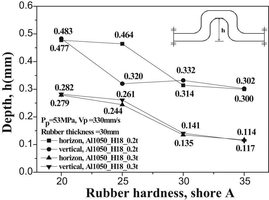
Stamping depth for different rubber hardness values for the considered aluminum blanks.
Figure 7 shows the forming depth as a function of punch velocity. A punch pressure of 53 MPa, plate thickness of 30 mm and a pad thickness of 30 mm (for a rubber with a Shore A hardness value of 20) were used in this experiment. The depth was found to be proportional to the velocity; the maximum forming depths in the horizontal and vertical directions at a velocity of 330 mm/s were 0.477 and 0.483 mm, respectively. It should be noted that there is little difference in the depth or the velocity values of 30 and 330 mm/s. This is because the bipolar plate reaches the forming limit due to the geometric constraint. Therefore, in all experiments a velocity greater than 30 mm/s barely changes the formability.
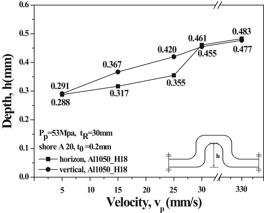
Stamping depth as a function of punch velocity for the considered aluminum blanks.
Thinning
Figure 8 shows the forming depth as a function of punch pressure. A punch velocity of 330 mm/s, and plate and rubber (Shore A harness value of 20) thickness values of 30 mm were used in this experiment. The depth was found to be proportional to the pressure, and the maximum forming depths in the horizontal and vertical directions at a pressure of 53 MPa were 0.477 and 0.483 mm, respectively. However, as previously mentioned cracks and fractures can occur in bipolar plates manufactured at pressures over 53 MPa. Therefore, it is clear that the critical pressure to fabricate a bipolar plate without defects must be identified.
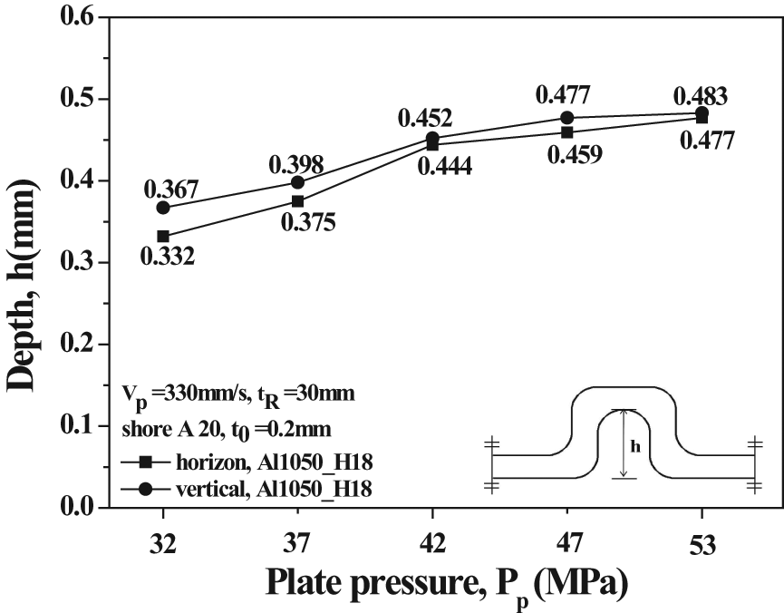
Stamping depth as a function of plate pressure for the considered aluminum blanks.
Figure 9 shows the definition of thinning (th) for the evaluation of formability in terms of forming depth. In this study, thinning is defined as the thickness variation ( = thickness of the formed plate – initial thickness) over the initial thickness.
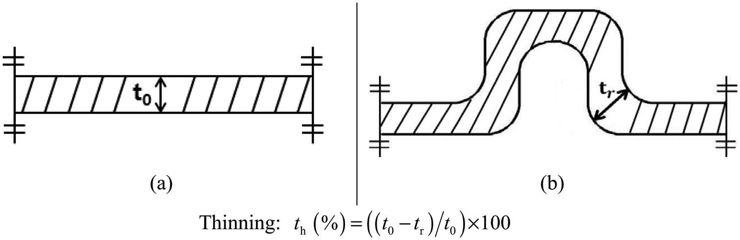
Definition of thinning (a) before the forming process (t0) and (b) thinning after forming process (tr).
Figures 10 and 11 show cross-sections of the 0.2 and 0.3 mm aluminum bipolar plates, respectively. As shown in these figures, the forming depth is proportional to the hardness of the rubber. However, as shown in Figure 10, noticeable thinning occurs in the 0.2 mm thick plate compared to that for the 0.3 mm plate. This is because the forming depth exceeded 0.4 mm, the target forming level. Also, it can be seen in Figure 10 that for a forming depth over 0.4 mm the thinning rapidly increases in proportion to the depth.
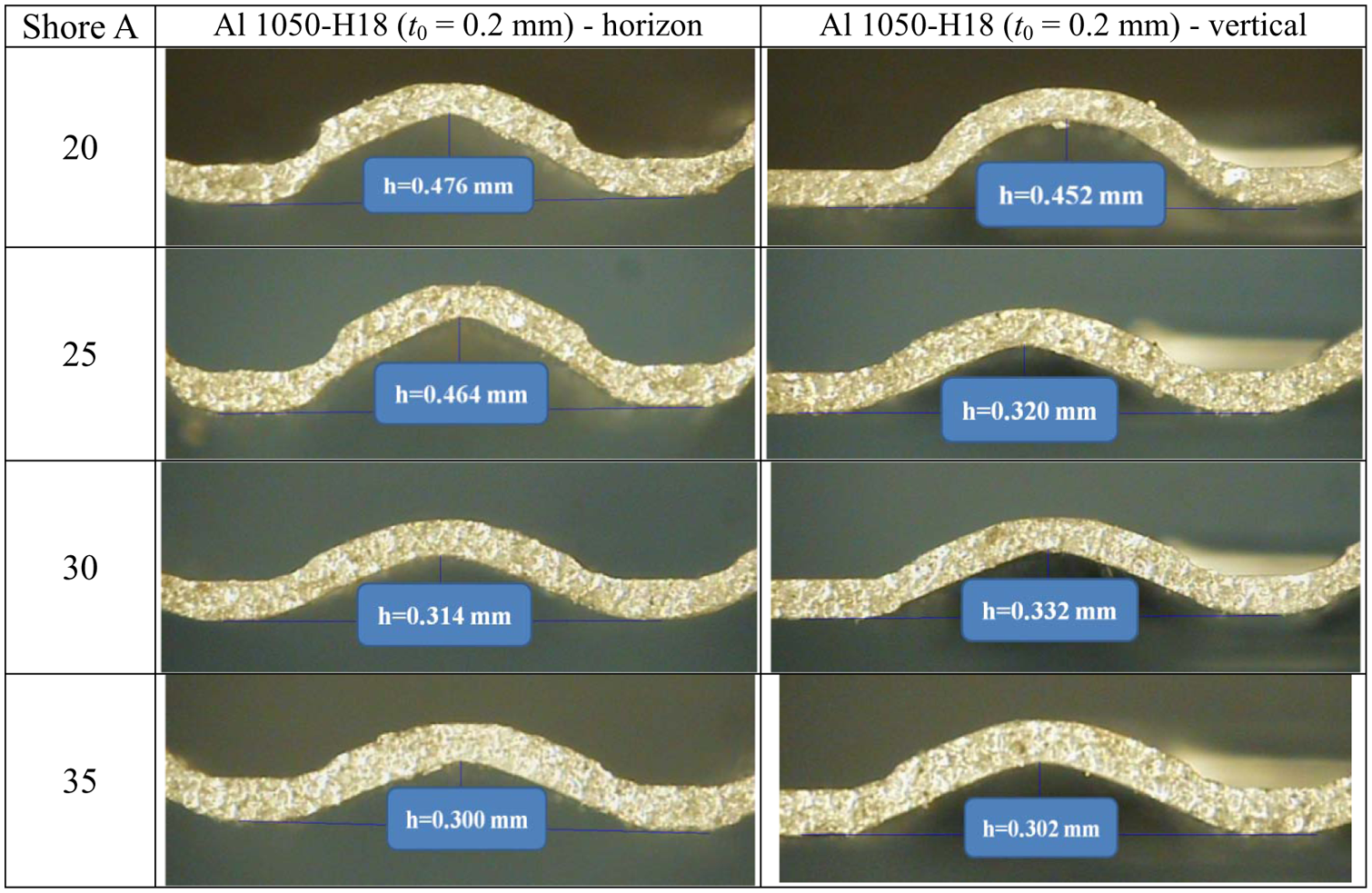
The structures of the 0.2 mm thick aluminum blanks for different Shore A hardness values for the rubber (rubber thickness: 30 mm, punch pressure: 53 MPa, punch velocity: 330 mm/s).
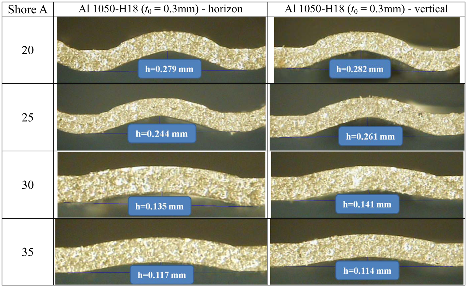
The structures of the 0.3 mm thick aluminum blanks for different Shore A hardness values for the rubber (rubber thickness: 30 mm, punch pressure: 53 MPa, punch velocity: 330 mm/s).
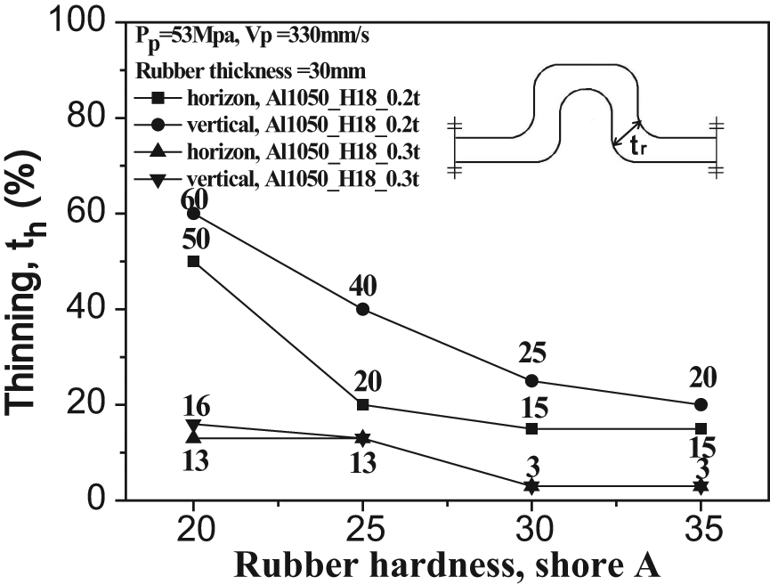
Figure 12 shows the thinning of the 0.2 and 0.3 mm thick plate samples as a function of the Shore A hardness value for the rubber. For the 0.2 mm thick sample the maximum thinning values in the horizontal and vertical directions of 60 and 50%, respectively, were found at a Shore A hardness value of 20. The equivalent minimum thinning values of 20 and 10%, respectively, were found at a Shore A hardness value of 35. The maximum thinning values for the 0.3 mm plate in the horizontal and vertical directions of 20 and 15%, respectively, were found at the Shore A hardness value of 20. The equivalent minimum thinning in the horizontal and vertical directions were commonly 3% and were found for Shore A hardness values of 30 and 35. From these results, as expected by considering Figures 10 and 11, it is clear that for the case of a forming depth over 0.4 mm, the thinning rapidly increases in proportion to the depth despite the small increase of the depth. Therefore, it is concluded that thinning increases rapidly as the forming limit is approached.
Relationship between thinning of the aluminum plate and Shore A harness value of the rubber.
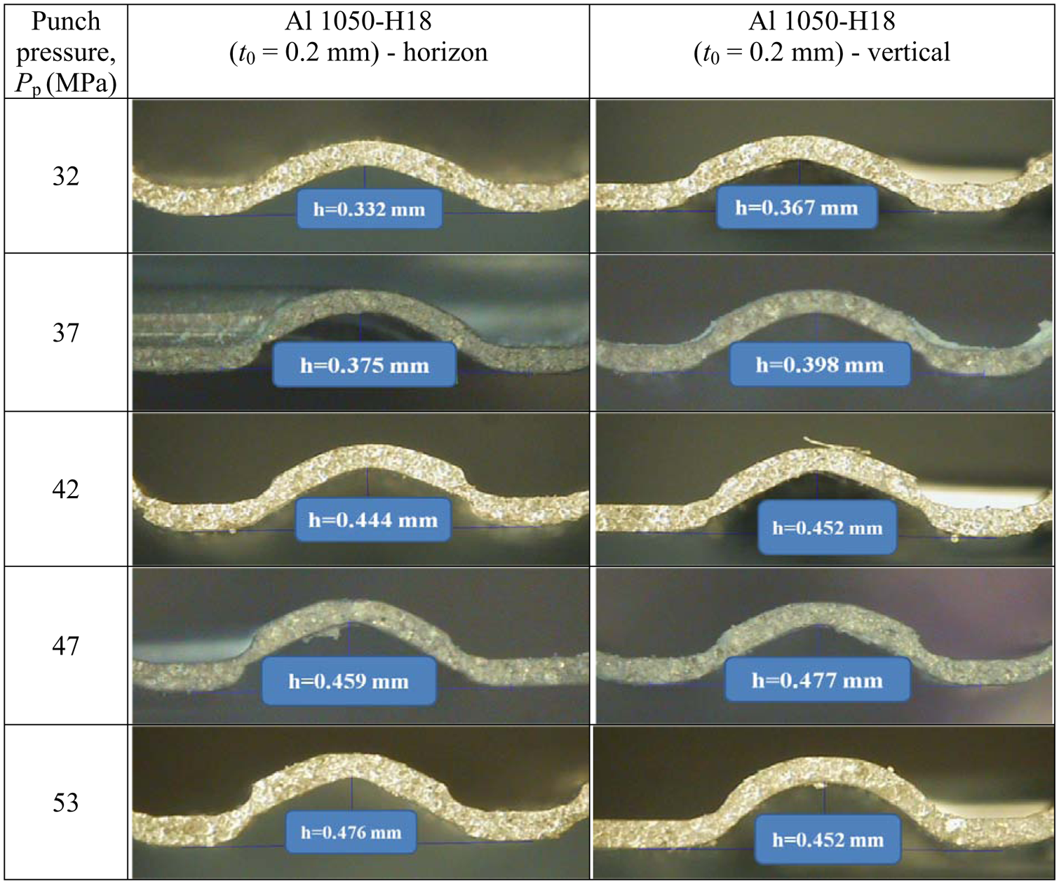
Figure 13 shows cross-sections of the 0.2 mm thick aluminum bipolar plates obtained at various punch pressures. It can be seen in this figure that an increase in punch pressure contributes to an increase in thinning. In particular, a remarkable thinning effect is observed to occur at punch pressures over 42 MPa. This is because the forming depth exceeds the 0.4 mm target level.
The structures of the 0.2 mm thick aluminum blanks at different pressures (rubber thickness: 30 mm, rubber hardness: Shore A hardness value of 20, punch velocity: 330 mm/s).
Figure 14 shows the thinning of the 0.2 mm samples as a function of punch pressure. The maximum thinning in the horizontal and vertical directions was 60% obtained at the pressure of 53 MPa and 50% obtained at the pressures of 42 and 53 MPa. Conversely, the minimum thinning values in the horizontal and vertical directions were 30 and 20%, respectively, obtained at a pressure of 32 MPa. It can be seen in this figure that the increase in the rate of the thinning could be reduced by adjusting the plate pressure. This is because the pressure reaches the forming limit due to the excessive thinning corresponding to the forming depth. Also, the pressure to cause thinning over 50% has little effect on the forming depth and thinning due to the same reason.
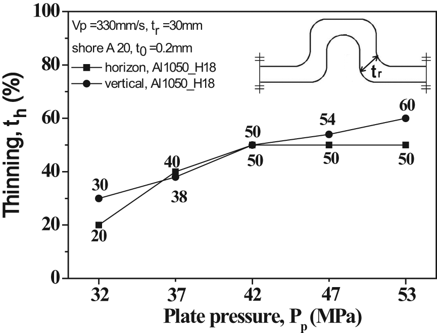
The thinning experience by the aluminum blanks as a function of pressure.
Figure 15 presents cross-sections of 0.2 mm thick aluminum bipolar plates obtained at different punch velocities. It is clear from this figure that the forming depth and thinning are proportional to the punch velocity. Also, noticeable thinning is observed in the bipolar plate at depths over the target value of 0.4 mm, see the pictures taken from 25 mm/s (Al1050-H18 (t0 = 0.2 mm) – vertical). For velocity levels greater than 25 mm/s it can be seen that the rate of thinning increased.
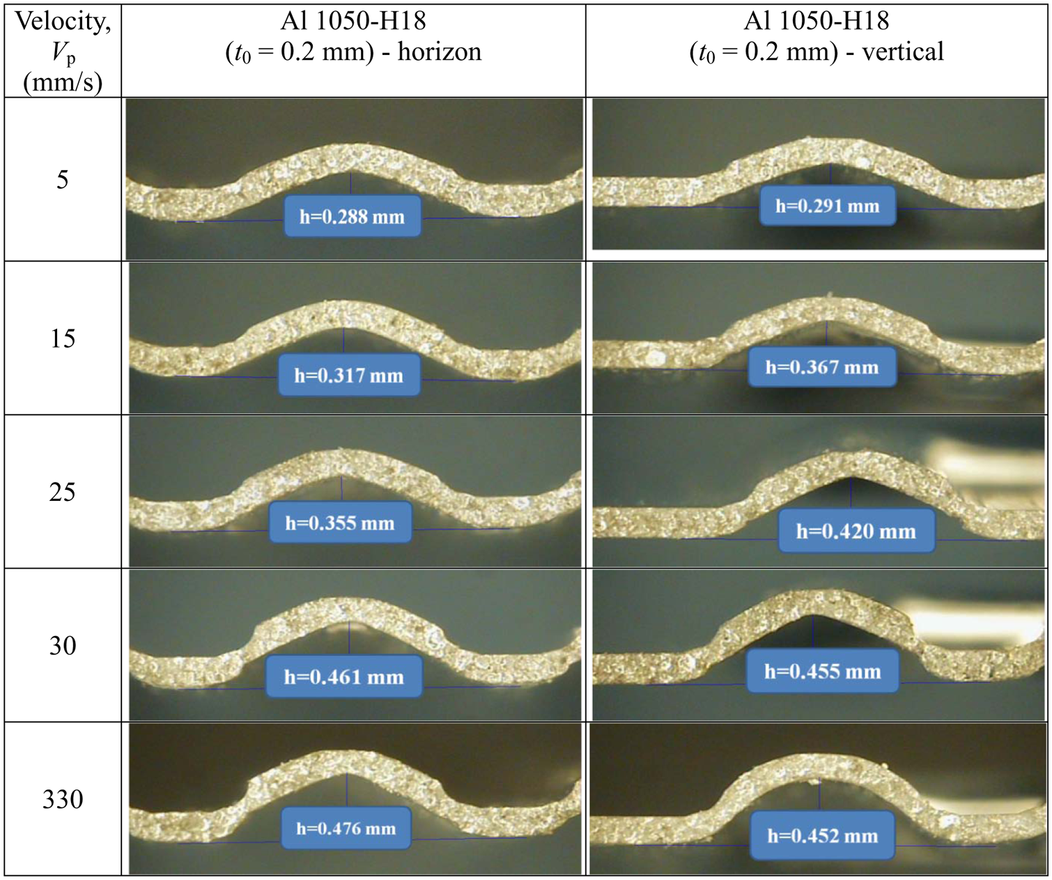
The structures of the 0.2 mm thick aluminum blanks at different velocities (rubber thickness: 30 mm, rubber hardness: Shore A 20, punch pressure: 53 MPa).
Figure 16 shows the effect of the punch velocity on the thinning of the 0.2 mm thick samples. The maximum thinning in the horizontal and vertical directions is commonly 50% at velocities of 30 and 330 mm/s. The minimum thinning is 15% at the velocity of 5 mm/s, regardless of the direction. In the low-speed section between 5 and 30 mm/s the thinning is proportional to the forming velocity. However, in the high-speed section the velocity has very little influence on the thinning. This is because the forming depth reaches the forming limit. Therefore, it is concluded that a very high velocity is not required to manufacture the bipolar plate.
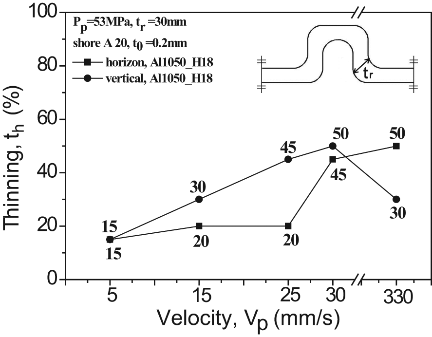
Effect of punch velocity on the thinning of the aluminum blanks.
Conclusions
The following conclusions can be drawn from the presented experiments on the formability of a bipolar plate manufactured from Al 1050 alloy using the rubber pad forming process.
For the rubber pad forming process, a rubber pad with an appropriate thickness is required, because this thickness has a significant influence on the forming depth. In addition, it is concluded that for the rubber pad a relatively low hardness level and a high punch pressure both contribute to an improved forming depth.
The forming depth is proportional to the punch velocity and pressure. However, a rubber with high hardness level causes a decrease in the depth. The maximum depth was obtained for a Shore A hardness value of 20, a rubber pad thickness of 30 mm, a punch velocity of 330 mm/s and a punch pressure of 53 MPa.
The thinning had an effect on the formability via its influence on the forming depth. The maximum thinning values for a 0.2 mm thick plate were 60 and 50% in the horizontal and vertical directions, respectively. The minimum thinning values for a 0.3 mm thick plate were 16 and 13% in the horizontal and vertical directions, respectively. In addition, it was found that the extent of thinning in the vertical direction was greater than that in the horizontal direction.
Footnotes
This work was supported by the National Research Foundation of Korea (NRF) grant Funded by the Korea government (MEST) (No. 20110000306) and by the human resources development of the Korea Institute of Energy Technology Evaluation and Planning (KETEP) Grant funded by the Korea government, Ministry of Knowledge Economy (No. 20104010100540).