
Abstract
Studies have been carried out to determine the effects of implementing alternating shielding gases for 6082T6 aluminium alloy welding. Alternating shielding gases is a newly developed method of supplying shielding gases to the weld area to enhance the efficiency of the standard gas metal arc welding process.
Alternating shielding gases involves discretely supplying two different shielding gases to the weld zone at a pre-determined frequency that creates a dynamic action in the weld pool. Several benefits have been identified in relation to supplying shielding gases in this manner, including reduced porosity, marginal improvements in mechanical properties, increased travel speed, and as a result of the lower heat input, reduced distortion. This method of shielding gas delivery therefore presents attractive benefits to the manufacturing community; namely the increased productivity and quality, in addition to a reduction in the amount of post-weld straightening required.
However, the literature available on this advanced joining process is very limited, especially so for aluminium alloys. For this reason, an evaluation has been carried out on the application of alternating shielding gases for the gas metal arc welding process on 6082T6 aluminium alloys.
Keywords
Introduction
Initially developed in the 1920s, gas metal arc welding (GMAW) is a fusion joining process in which an arc is established between a continuously fed filler wire electrode and the workpiece.
Shielding gases are fundamental to most welding processes; their primary purpose being to protect the molten weld pool from contamination by atmospheric gases. In addition, computational models have shown that the shielding gas implemented in the GMAW process can be selected to tailor the weld to meet a desired specification. 1 There are a number of shielding gases commonly used, each with its own specific properties,1–9 which can have pronounced affects on the arc characteristics, mode of metal transfer, cleaning action, penetration level and weld shape. Consequently, the shielding gas can also have a positive influence on the travel speed as reported by Gillies et al. 9
The shielding gas used is selected depending upon the material to be welded. There are two commonly used gases employed for the welding of aluminium, argon and helium. Shielding gases are also commonly utilised in a variety of premixed combinations in order to take advantage of the beneficial properties of each gas.10,11 For example, pure helium is seldom used across Europe owing to its high unit cost, although mixed gases containing specific ratios of argon and helium are often encountered.
It is widely recognised that additions of helium to a shielding gas combination can have beneficial effects on increasing the penetration depth of a weld. Jönsson et al. 12 reported on the effects that either argon and helium have on the temperature distribution within the arc column. They concluded that helium produces a narrower temperature distribution and higher temperature at the surface of the workpiece, as shown in Figure 1, 12 resulting in a more contracted weld bead with greater penetration. This is a consequence of helium having a higher first ionisation potential than argon, this results in helium having a higher arc power density and, therefore, produces a more constricted cathode spot generating greater penetration. However, owing to the high unit cost of helium, it is only normally implemented in thicker sections.
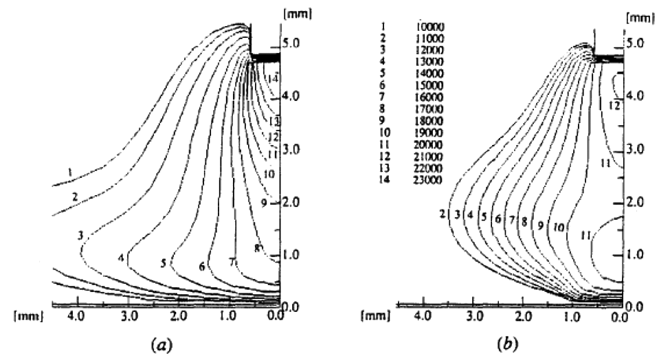
Temperature contours for (a) argon, and (b) helium at a 200 A welding current (with kind permission from Springer Science+Business Media). 12
Several industries 13 are moving towards thinner, lighter and stronger materials (such as AA6082T6) to reduce the overall mass of the structure and with the aim of improving efficiency. For example, the transportation industries are continually striving to increase fuel efficiency as a consequence of increasing oil prices and the introduction of legislation governing exhaust emissions. It has been reported that a 10% reduction in weight corresponds to a 5.5% reduction in fuel consumption, with each kilogram saving said to equate to a 20 kg reduction in CO2 emissions over a 170,000 km lifetime, and since the density of aluminium is approximately one-third that of steel, there is considerable scope for improvement. Aluminium alloys also have a use in the shipping industry where its use allows for a smaller portion of the ship to be beneath water level allowing for a greater number of passenger decks. Aluminium alloys are also used higher up the naval structure in order to enhance structure stability. Al–Cu–Mg (2xxx series) alloys are used extensively in the aerospace sector, however, movements are being made towards 6xxx series alloys owing to benefits associated with improved weldability and cost, with the added benefit of weight saving as a consequence of not requiring cladding to prevent corrosion.
However, it is widely acknowledged that, during welding, thinner aluminium alloy plates are also more susceptible to heat induced distortion owing to their lower stiffness. Distortion is the result of the non-uniform expansion and contraction of the weld material owing to the heating and cooling cycle 14 and with a higher thermal expansion coefficient, aluminium alloy structures are more susceptible to distortion than steel structures. Computational models have been developed to help predict distortion;15–17 in spite of this, as a result of distortion being closely related to the weld heat input, it is of paramount importance to eradicate as much heat input as possible in order to mitigate the final distortion level. Post-weld fabrication techniques such as flame straightening18–20 are commonly used to remove distortion from the structure; nevertheless, this method is highly resource intensive, does not add value to the final product and potentially degrades the material properties in the heated region. Therefore, reducing the initial distortion is of economic and practical importance. Other methods of reducing the induced distortion include friction stir welding 21 and thermal tensioning; 22 this method utilises additional heat, on specific areas of the structure, with the aim of altering the residual stresses present within the structure.
Recently, there has been positive research into the effects of implementing alternating shielding gases.1–5 This method involves discretely supplying two different shielding gases to the weld pool in order to take advantage of the beneficial properties of each gas. Kang et al. 4 reported that argon and helium produce weld pool flow vectors opposite in direction, as shown in Figure 2. 4 This technique of alternating shielding gases has been reported to produce an additional preferential effect within the weld pool in the form of a dynamic action caused by complex flow patterns generated when fluctuating between shielding gases. Kang et al. 4 reported that this dynamic action is a result of three independent phenomena: arc pressure variation, variation of weld pool fluidity and arc pressure peaking. These phenomena combine to produce a stirring action within the weld pool, which, coupled with the increased pool fluidity when welding with helium, help gas pores escape thus reducing porosity.
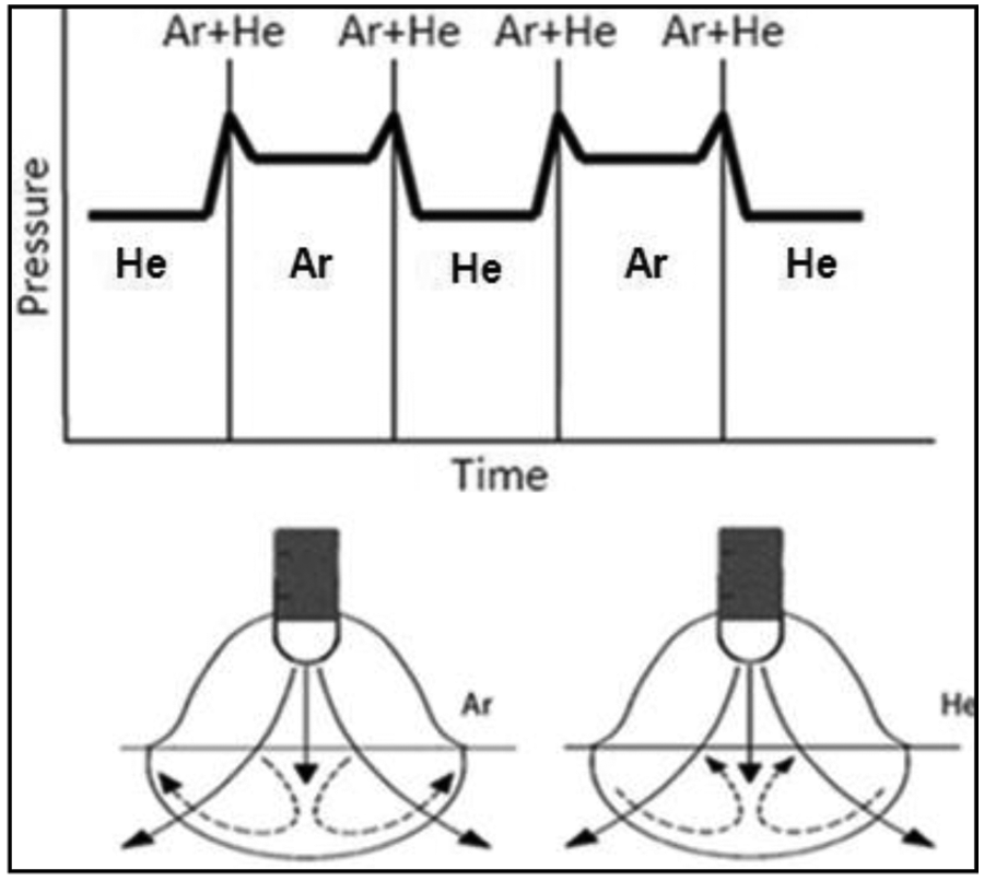
Arc pressure and fluid flow vectors (reprinted with permission from Elsevier). 4
Lin and Eagar 23 reported that helium creates a smaller peak pressure and wider pressure distribution than that of argon in gas tungsten arc welding. As a result, helium would have greater radial momentum dissipation than argon and consequently a lower peak pressure at the workpiece surface. Premixed shielding gases provide a constant arc pressure and consequently constant arc force, whereas, when implementing alternating shielding gases, there is a build up in-line pressure when the valve is closed which, when opened, results in a pressure impulse and a consequential arc force impulse.
A reduction in heat input can be achieved by increasing the speed of travel, although this is only an option if not adversely affecting the mechanical properties of the welded joint. Initial studies 2 have shown beneficial results including increased travel speed, reduced porosity and improved mechanical properties in a steel structure. Campbell et al. 2 reported that the use of alternating shielding gases can considerably reduce distortion in thin plate DH36 steel as a result of reducing the heat input owing to increasing the speed of travel, this has also given rise to a reduction of 17% in overall weld costs. It has also been shown, via the aid of computational models, that the application of alternating shielding gases permits an increase in travel speeds while generating welds meeting specified geometry requirements and quality. 1
Shielding gases are primarily used to protect the weld pool from contamination, however, owing to a variety of reasons, including inadequate shielding gas flow, excessive shielding gas flow, cross drafts and damaged welding apparatus, insufficient protection of the weld pool is often provided that can lead to defects such as porosity in the solidified weld metal. Porosity formation in aluminium occurs owing to hydrogen being drawn into the electric arc and is a serious issue with respect to this material. Hydrogen is dissociated, absorbed into, and spread throughout the weld pool. During solidification of the weld pool, hydrogen gas bubbles form, some of which are able to escape from the liquid weld metal owing to buoyancy effects. However, gaseous hydrogen that does not escape when the weld pool solidifies creates voids in the solid weld metal. As a result of hydrogen having a higher solubility in molten aluminium and very low solubility in solid aluminium, there is potential for excessive amounts of porosity to be present in the final weld. The dynamic action reported by Kang et al. 4 assists with the buoyancy effect in removing these hydrogen bubbles, thus reducing weld porosity.
Min et al. 24 reported that the weld heat input affects the recrystallisation of the heat affected zone (HAZ) in magnesium alloys with an increase of less than 50% resulting in grains more than double the original grain size. In contrast, Campbell et al. 2 showed that a finer grain structure was produced in DH36 steel when implementing the use of alternating shielding gases and a lower heat input. Their work 2 also showed that a finer homogeneous grain structure consequently resulted in more uniform material properties throughout. This is to be expected, as a finer grain structure results in a higher density of grain boundary interactions and, therefore, requires more energy to allow a dislocation to propagate. It follows that the yield strength is related to the grain size through the Hall–Petch equation

where
Based on the above, the objective of this study is to evaluate the benefits of using alternating shielding gases during GMAW in comparison to conventional shielding gases.
Experimental set-up
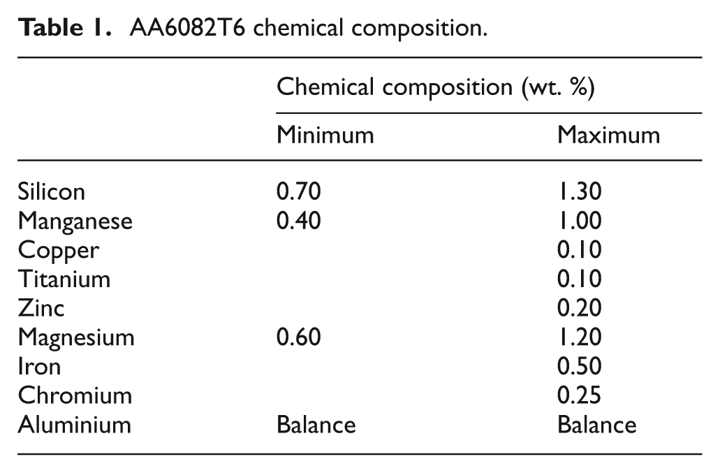
In the present study, a series of welding trials were performed on 6082T6 aluminium with a typical chemical composition shown in Table 1. Trials were performed on 6 mm thick 6082T6 aluminium in the form of 125 × 250 mm plates with a 30° angle machined while leaving a 1.5 mm root face with a ceramic backing strip applied to the underside of the weldment. The weld trials were performed using an invertor power supply with a DC electrode
AA6082T6 chemical composition.
Weld parameters.
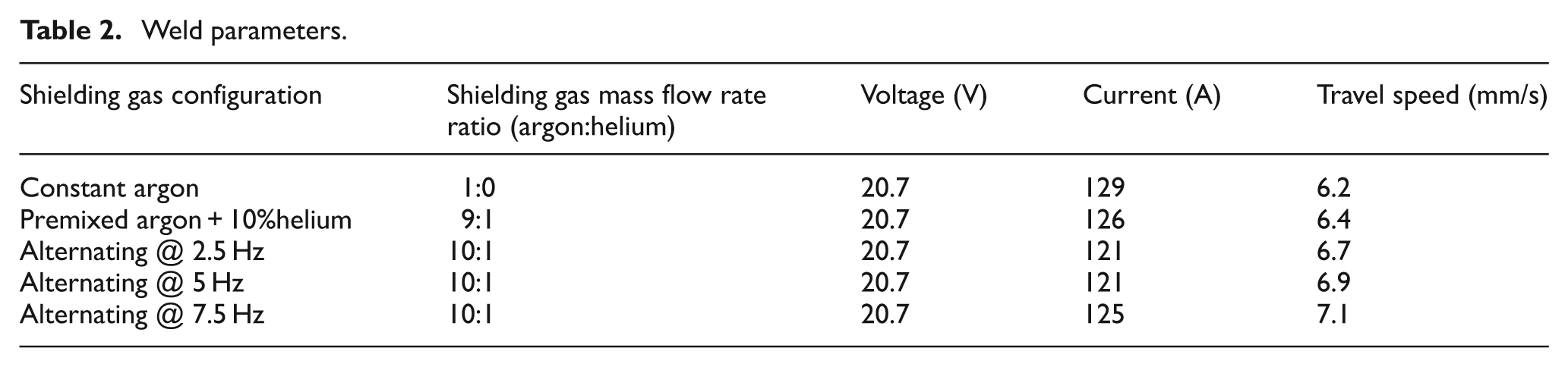
Three separate shielding gases were used throughout this experimental programme as follows and in each case a flowrate of 15 l/min was adopted when flowing continuously:
Pure argon.
Pure helium.
Argon+10%helium.
This allowed a number of comparisons to be made between the effects of (a) alternating gases (controlled pulsations of pure argon and pure helium at pre-determined frequencies), (b) pre-mixed argon+10% helium, and (c) pure argon that was used as the base case for comparison.
The alternating frequency of the shielding gases was controlled through the use of a dedicated electronic gas control unit (Figure 3 insert). The basis of which being two 555 timing circuits, which, set in ‘astable’ mode produces a continuous square wave at a specified frequency. The output from the two circuits then controlled the current supply to two solenoid valves in order to regulate the flow of each gas. An oscilloscope was then implemented to validate the output of the unit.
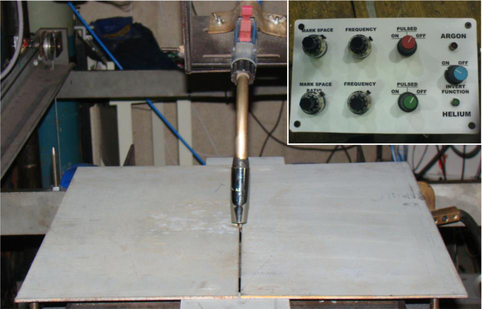
Automatic welding rig (insert: electronic gas control unit)
The unit used to control the flow of gases is an experimental unit that is not currently commercially available. The unit was minimal in cost to generate, nonetheless, any modest capital investment is likely to be substantially outweighed by the potential savings and benefits identified.
The welding nozzle was modified (Figure 4) in order to limit the degree of pre-mixing of the shielding gases in the gas supply line. In doing so, this allowed for helium to be supplied directly to the welding region through the second inlet.
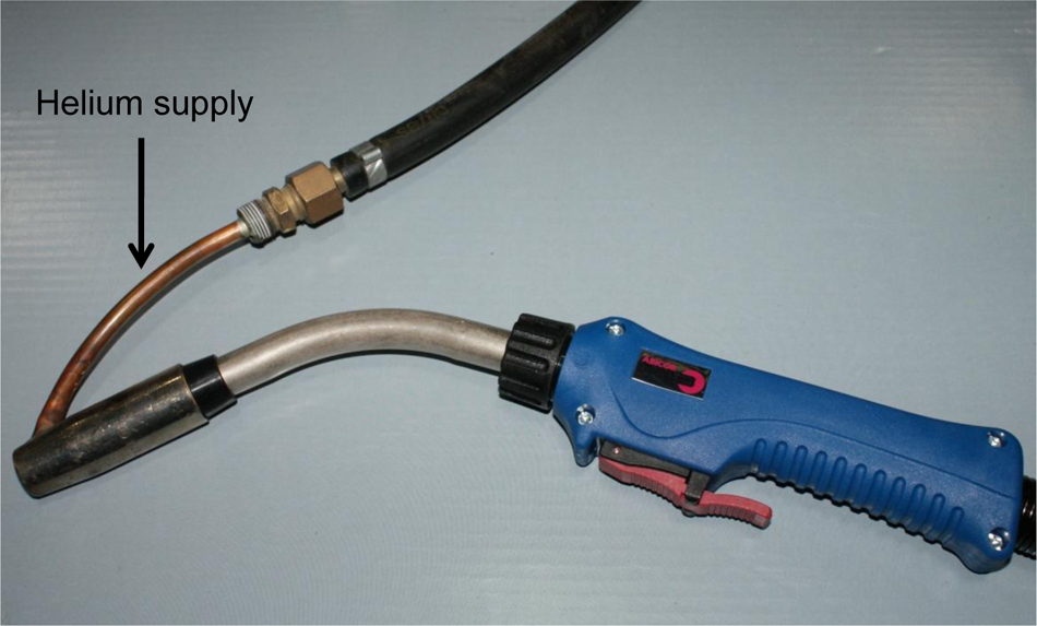
Welding torch with adapted nozzle.
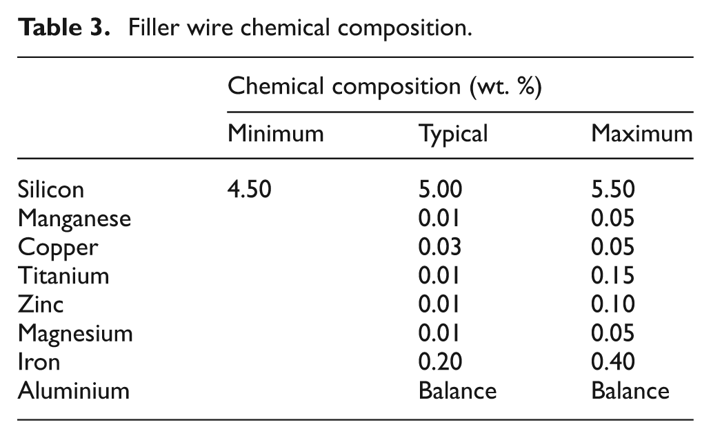
It is important to recognise that, although the alternating frequency is a variable during experimentation, each gas is supplied for 50% of the time regardless of the frequency. Since the flow rate of each gas was pre-set at 15 l/min, the overall gas consumption remains 15 l/min independent of the frequency. As previously indicated, there would also be a slight peak in flow rate owing to the pressure impulse when alternating between gases as a result of a build-up in line pressure. The filler wire used throughout was 1.2 mm diameter Alumig Si5 4043 aluminium wire with the typical chemical composition shown in Table 3.
Filler wire chemical composition.
All welds were performed on an automatic welding rig (Figure 3), which held the plate rigid while moving at a pre-set speed under a fixed welding torch. The rig also allowed for distortion measurements to be taken through the use of an optical distance sensor that scanned the workpiece according to a pre-determined grid pattern before welding, and after a cooling period the difference between the two scans being the weld induced distortion. The plates were positioned upon four corner locating points, each of which were calibrated using the optical sensor to result in zero deformation at these locations.
Thermal data for each weld was captured using both a thermal imaging camera and K-type thermocouples at the mid-point of the plates, between 10 and 80 mm from the weld centreline in 10 mm increments. It was assumed that the temperature distribution within the plates was symmetrical, hence, readings were captured from one side of the weld. The thermal imaging camera was positioned directly above the weldment and analysed using the ThermaCAM Researcher programme, this confirmed the symmetry assumption. Prior to welding, the workpieces were coated with high emmisivity paint (≅1) to ensure accurate data collection by the thermal imaging camera.
A pre-calibrated, portable arc monitoring system (PAMS) unit was used throughout experimentation to accurately obtain the welding arc voltage and current. The sample frequency of 5 kHz allowed for an accurate representation of the welding parameters and permitted a clear understanding of how the gas configuration affected these parameters.
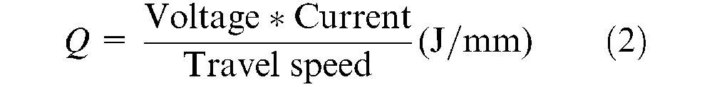
Using the data obtained from the PAMS unit, the average heat input (Q) was calculated for each shielding gas using equation (2), as shown in Table 4. Here, the data was determined using a thermal efficiency factor of unity, as the thermal effects of the different shielding gases are highly complex and unknown at this particular stage. However, it is appreciated that, in reality, the thermal efficiency factor would take into account a number of variables (wire stick-out, voltage, current, shielding gas, etc.) and these would have a cumulative effect on the true thermal efficiency factor of the system.
Heat input.
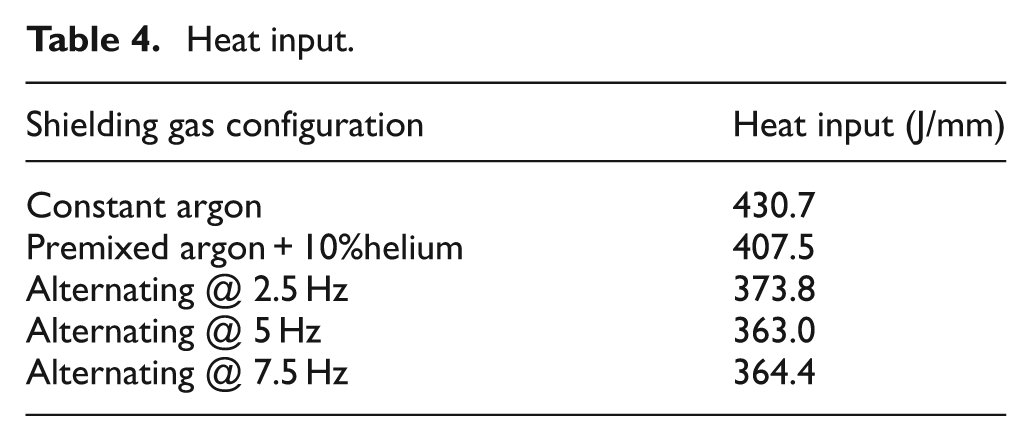
The heat input is an important consideration given its relationship with induced distortion. The heat input for the alternating cases is greatly reduced as an outcome of the increased travel speed. The level of heat input is not only of paramount importance to the induced distortion, but it also affects the recrystallisation rate of the HAZ2,24 and can, therefore, have detrimental effects on the mechanical properties of the weld area.
Preliminary experiments were conducted in the form of bead on plate trials to determine the travel speed required to produce equivalent levels of penetration. This determined that for each 2.5 Hz increase in alternating frequency, a 0.2 mm/s increase in travel speed could be permitted. This theory was then extended to the butt weld set-up, in which a number of trials were conducted at 2.5 Hz to determine what travel speed would result in full penetration of the joint.
Results and discussion
Distortion
Distortion poses major problems in industry since many lightweight structures are constructed by the assembly of sub-structures of increasingly stringent tolerances. Therefore, limitation of distortion is desirable in the final product to ensure accurate fit-up. For this reason, manufacturing companies strive to reduce the level of distortion at source and thus reduce the rework required to ensure assemblies fit together. This is largely achieved through good welding practices, primarily related to reducing the weld heat input and the application of heat in specific areas.
In the present study, the material deformed in a classical saddle-like shape owing to the longitudinal and transverse shrinkage in the plate, an example of which is shown in Figure 5. Table 5 shows the percentage reduction in the maximum distortion experienced by the structure as a function of the shielding gas configuration when compared with the argon base case. The lower heat input, as a result of the increased travel speed, permitted through the addition of helium to the shielding gas configuration has therefore resulted in an overall reduction in distortion; the premixed argon + 10%helium gas has reduced the maximum distortion present by 12%, whilst the use of alternating shielding gases resulted in a considerable reduction of 25–36%.
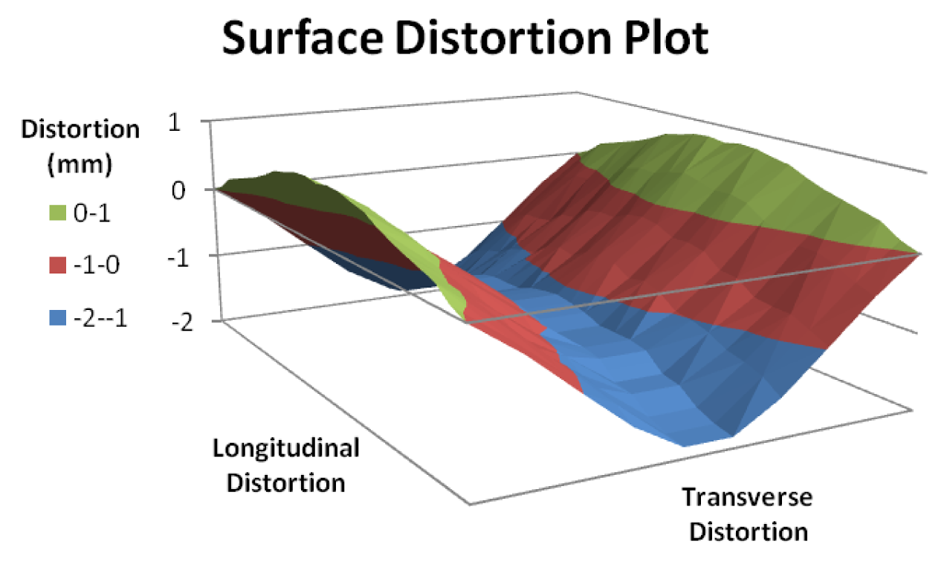
Typical surface distortion plot.
Distortion measurements.
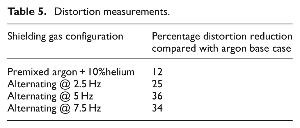
The level of distortion in each plate has been shown to be proportional to the amount of welding heat input. The reduced heat input for the alternating cases, as a result of the increased travel speed, therefore correlates with the reduction in distortion achieved by supplying a premixed shielding gas and by the alternating method. This is a result of the alternating method taking advantage of the supply of pure helium, which produces greater penetration than argon owing to its higher first-ionisation energy producing a smaller cathode spot.
Thermal data
Thermal imaging data was collected in order to validate the data obtained through the use of thermocouples. Figures 6 and 7 show the data produced through thermal imaging and thermocouples, respectively. The points indicated on the thermal imaging are the locations of each thermocouple and their values show good correlation to that recorded by each thermocouple.
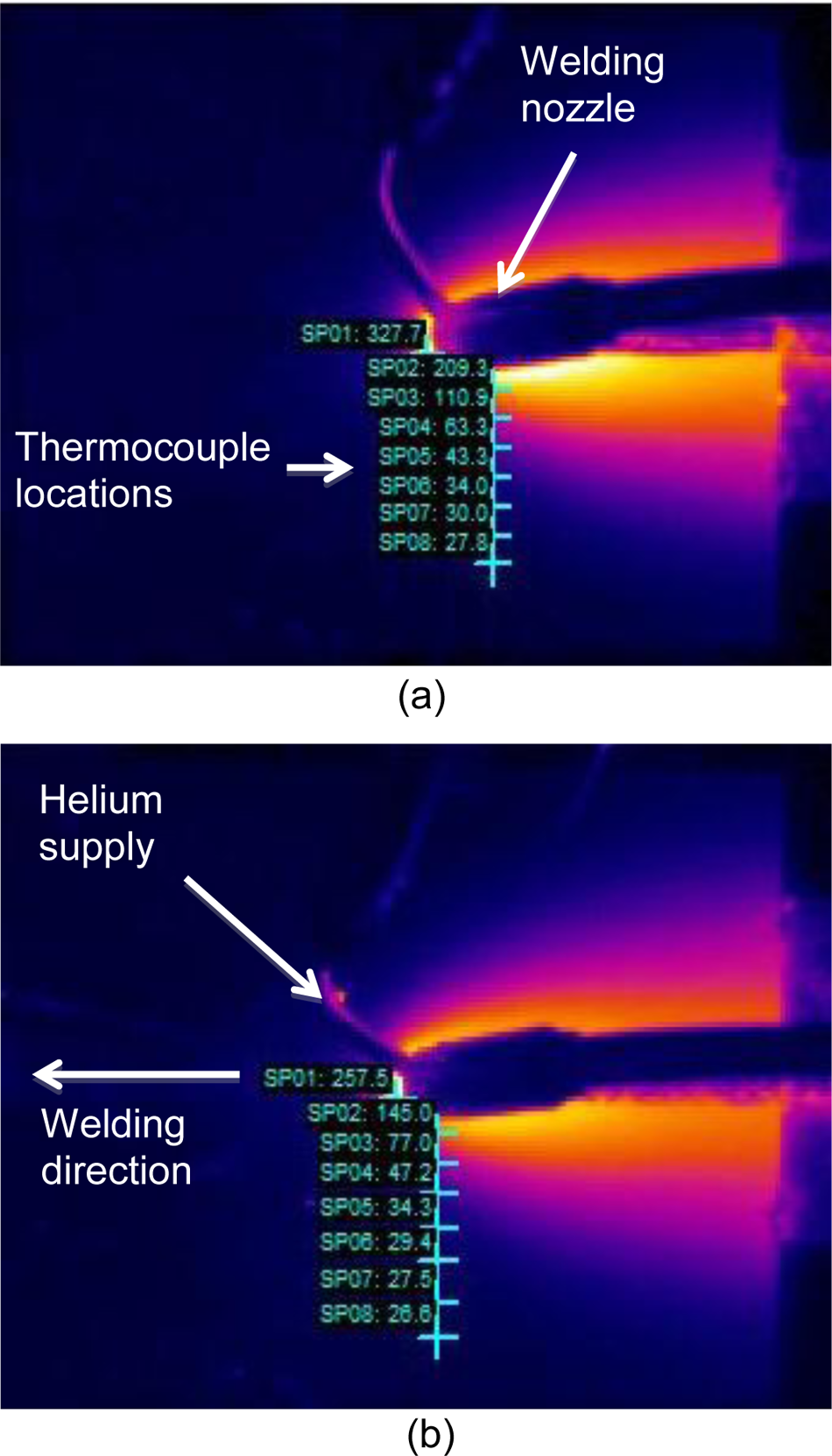
(a) Thermal imaging data – constant argon. (b) Thermal imaging data – alternating at 7.5 Hz
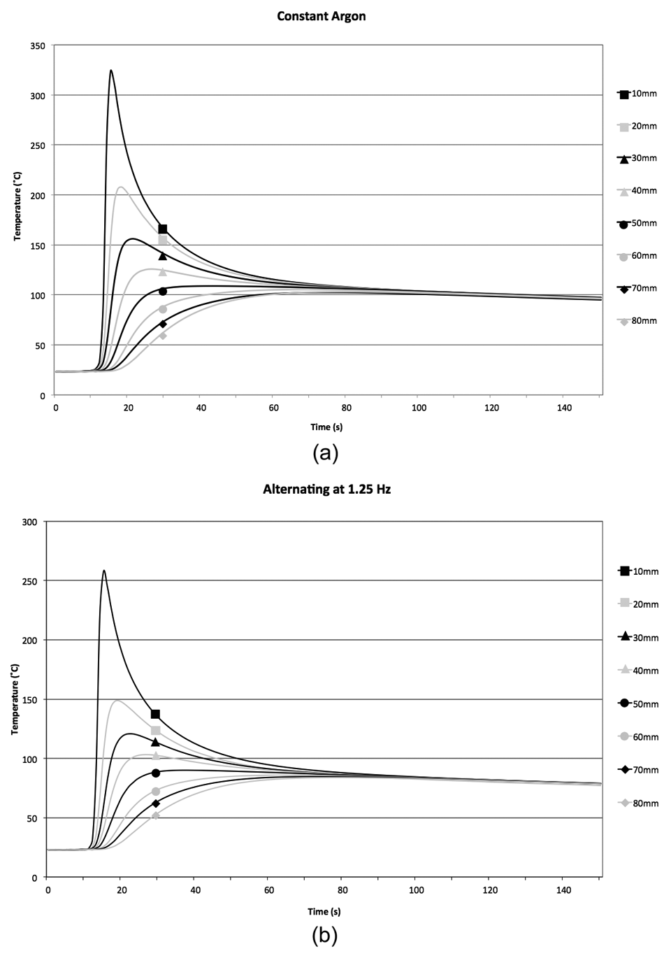
(a) Thermocouple data – constant argon. (b) Thermocouple data – alternating at 7.5 Hz
The peak temperature, i.e. 10 mm from the weld centre line, and the temperature distribution of the alternating gas cases are shown to be considerably reduced compared with the premixed argon+10%helium gas and the argon base case. The peak temperature of the alternating cases (∼260 °C) were found to be approximately 70 °C lower than that of the constant argon case (∼330 °C), while the premixed argon+10%helium case was approximately half way between (∼300 °C). This is a result of both the reduced heat input and the narrower arc column produced by helium. 12 The results also correspond to those obtained by Campbell et al. 2 who found that the peak temperature, when implementing alternating shielding gases in a steel structure, was reduced.
Key weld geometries and defect level
In order to assess any effects that the various shielding gas supply methods have on the microstructure and HAZ of the weld, metallographic analyses were performed on a sample from each shielding gas configuration.
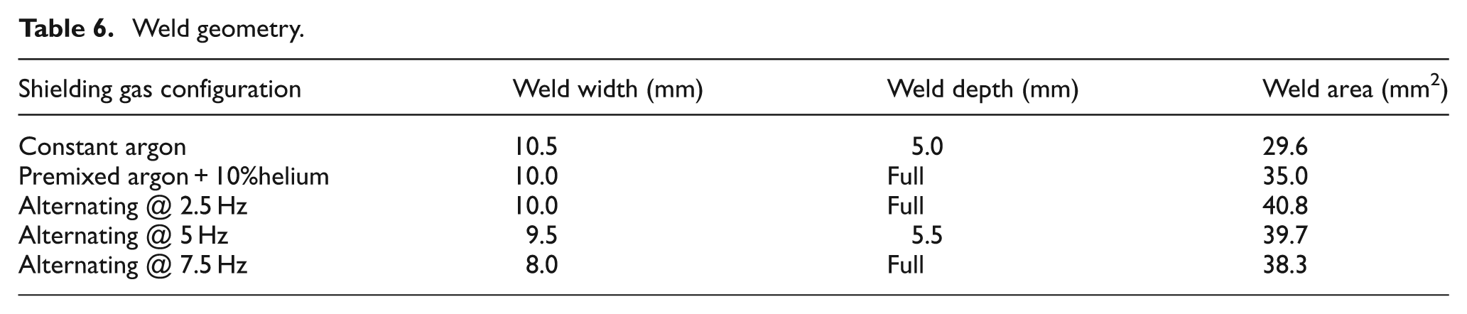
Helium is generally used on thicker sections of material owing to its ability to increase penetration. As reported by Jönsson et al. 12 helium is generally added to gas combinations owing to its ability to increase the weld depth:width ratio in comparison with constant argon. This has also been shown to be the case when implementing alternating shielding gases, even with a faster travel speed, as shown in Table 6 and depicted in Figure 8. The weld area indicates that the shielding gas configuration has a pronounced effect on the melting efficiency; with the addition of helium to the shielding gas (both in the premixed and alternating cases) resulting in a greater weld area than the constant argon base case. When comparing the helium content shielding gas configurations, alternating shielding gases was found to generate a larger weld area than the premixed argon+10%helium shielding gas. While the frequency of alternation does not appear to have a huge influence on the weld area, the small difference generated between each frequency is a result of the different travel speeds implemented.
Weld geometry.
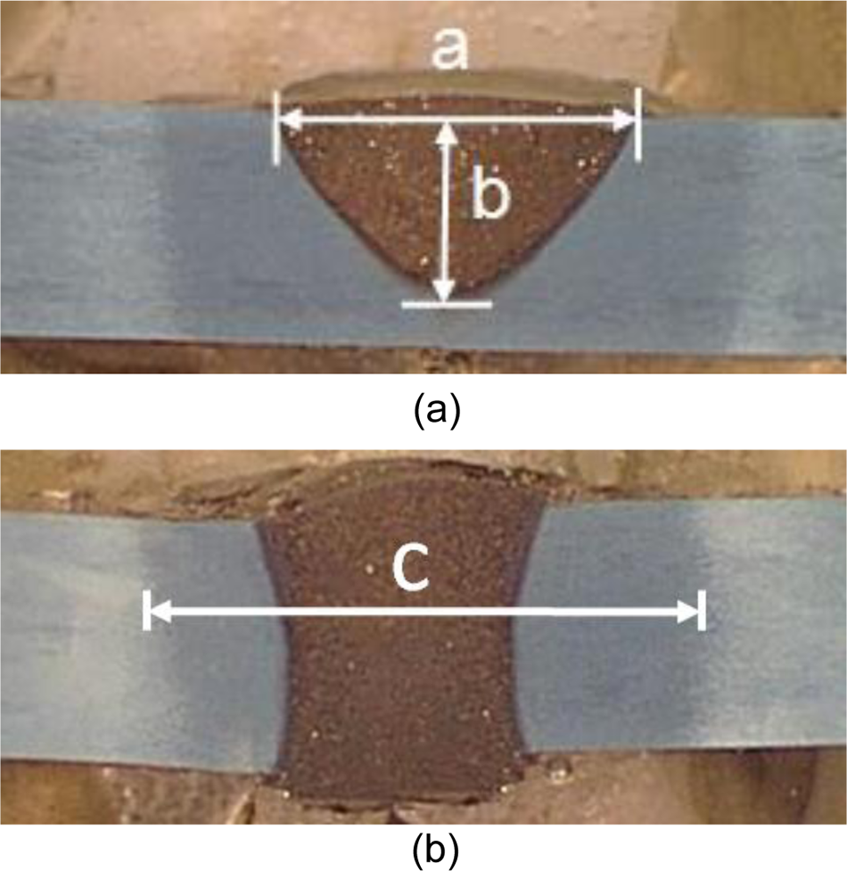
(a) Macrograph (constant argon) showing measurements for weld width and penetration. (b) Macrograph (alternating at 7.5 Hz) showing increased penetration and measurement for the HAZ width.
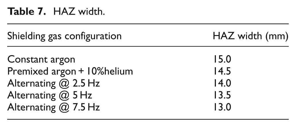
The width of the HAZ is the area of the parent plate that had been affected by the weld heat input. The width of the HAZ, Table 7, is shown to be reduced in the case of premixed and alternating shielding gases. This is, in part, owing to the reduced heat input, as a result of the increased travel speeds permitted, but also a consequence of the more constricted arc column of helium that had been reported by Jönsson et al. 12 Moreover, it has been shown that increasing the frequency of alternation further reduces the HAZ width, primarily linked to the increased travel speed.
HAZ width.
The percentage porosity was determined using Image-Pro Plus, which analysed the micrograph images of the weld pool and calculated the percentage of the image above a specified shade. Examples of the analysed images are shown in Figure 9 and the percentage porosity for each gas configuration is shown in Table 8.
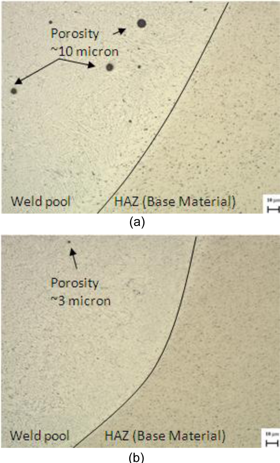
(a) Micrograph (constant argon) showing fusion boundary and porosity. (b) Micrograph (alternating at 7.5 Hz) showing fusion boundary and reduction in porosity.
Percentage porosity.
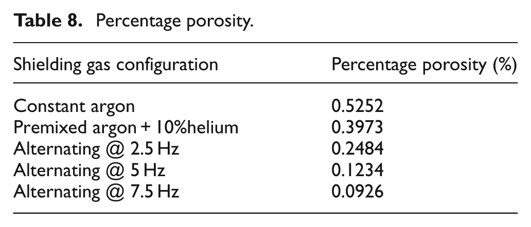
The premixed argon+10%helium mixture produced a reduction in percentage porosity compared with the argon base case that has been attributed to the increase in weld pool fluidity. It can also be noted that the percentage porosity is further reduced through the application of alternating shielding gases, this confirms the findings of Kang et al. 4 who demonstrated that alternating shielding gases can reduce the porosity present in the welding of 1420 and 1460 aluminium. It was reported that this was a result of alternating shielding gases generating a dynamic action within the pool, aiding the gas bubbles escape the molten weld pool. It has also been shown that increasing the frequency of alternation can further reduce the levels of porosity present within the weld.
Mechanical properties
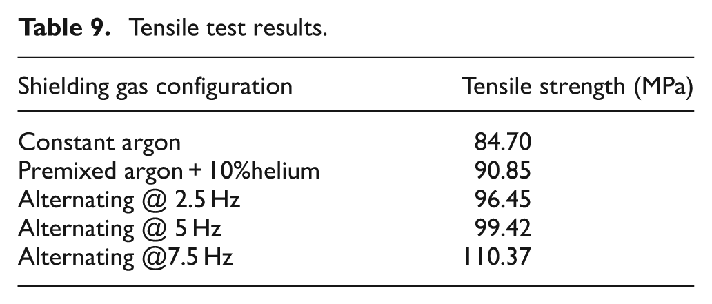
Transverse tensile tests were carried out, the results of which can be seen in Table 9, as anticipated, all samples failed in the weld. As can be seen, the base case of constant argon produced a weld strength of approximately 85 MPa, while using a premixed argon+10%helium gas produced a strength of approximately 91 MPa and providing alternating shielding gases produced welds with strength in the region 95–110 MPa. It has been shown that the frequency of alternation also has an influence on the tensile strength of the weld, with an increased frequency resulting in an increased strength. The tensile strength of the weld is shown to follow the same trend as the percentage porosity, in that an increasing frequency of alternation produced less porosity and consequently increased the tensile strength of the weld.
Tensile test results.
In a previous study using alternating shielding gases while welding steel, 2 it was found that a finer grain structure was generated as a consequence of accelerated cooling from a higher temperature. This helped achieve an increase in mechanical properties, and the reduction in porosity could also be partly attributed to the finer grain distribution.
Root bend tests were carried out to ensure that no negative effects were associated with the application of alternating shielding gases.
Conclusions
The main benefits associated with alternating shielding gases, is related to the increase in travel speed and the consequential reduction in distortion. This is recognised to be owing to the addition of helium, which compared with argon has a higher first ionisation energy and, consequently, permits a faster travel speed while maintaining equivalent levels of penetration. The reduction in distortion is a consequence of the reduced heat input, and the narrower arc column produced by the addition of helium resulting in a narrower HAZ. As a result of the pressure peaking present in alternating shielding gases, there is a momentarily greater arc force, thus permitting even faster travel speeds than the premixed helium addition while maintaining equivalent penetration.
Although no economic evaluation was completed, a previous study 2 performed a comprehensive analysis for the application alternating shielding gases on DH36 steel that showed a 17% reduction in cost as a result of the reduction in man-hours required.
The premixed argon+10%helium case has shown a reduction in the percentage porosity present within the solidified weld. This has been attributed to the increased weld pool fluidity as a result of the addition of helium, thus aiding the gas bubbles escape the molten metal. It has also been shown that, in the case of AA6082T6, the application of alternating shielding gases can further reduce the level of porosity present within the weld. This is mainly attributed to a combination of the variation in weld pool fluidity and also the dynamic action that the weld pool experiences owing to the fluctuation between different shielding gas environments.
The addition of helium, both in the premixed case and the alternating gas configurations, has resulted in an increase in transverse tensile strength of the weld. In addition, it has also been shown that the frequency of alternation can have a pronounced effect on the mechanical properties of the weld, with an increase from 2.5 Hz to 7.5 Hz resulting in approximately 15 MPa increase in tensile strength. However, no detrimental effects were found when subjected to bend testing.
It is, therefore, considered that, compared with the use of pure argon or argon+10%helium shielding gases, the application of alternating shielding gases in the GMAW process is highly suited to the welding of AA6082T6 components and offers the manufacturing community clear benefits in terms of increased productivity, reduced porosity, moderate strength increase and a reduction in post-weld straightening.
Footnotes
The authors would like to acknowledge the funding provided by BAE Systems Surface Ships Limited which has made this research possible.