
Abstract
This study implemented an iterative experimental approach in order to determine the shielding gas flow required to produce high-quality welds in the gas metal arc welding process with alternating shielding gases when subjected to varying velocities of cross drafts, thus determining the transitional zone where the weld quality deteriorates as a function of cross-draft velocity. An artificial neural network was developed using the experimental data that would predict the weld quality based primarily on shielding gas composition, alternating frequency and flow rate and cross-draft velocity, but also incorporated other important input parameters, including voltage and current. A series of weld trials were conducted to validate and test the robustness of the model generated. It was found that the alternating shielding gas process does not provide the same level of resistance to the adverse effects of cross drafts as a conventional argon/carbon dioxide mixture. The use of such a prediction tool is of benefit to industry in that it allows the adoption of a more efficient shielding gas flow rate, while removing the uncertainty of the resultant weld quality.
Keywords
Introduction
Gas metal arc welding (GMAW) is one of the most common fusion joining processes used in industry due to various advantages it possesses in comparison to other joining methods. Shielding gases are a fundamental component of the GMAW process; their primary purpose is to protect the welding region from contamination by atmospheric gases. There are a number of shielding gases used throughout the world, and the selection is generally dependent upon the economic availability of each gas as well as the material and welding set-up being welded. Each gas has specific properties that affect the arc characteristics, and subsequently influences various weld aspects, including the solidified weld geometry 1 and mechanical properties. 2
Shielding gases are also commonly used in a variety of premixed configurations of two or more gases in order to take advantage of the beneficial properties of each. In the European shipbuilding industry, the most common shielding gas used is an Ar:20%CO2 mixture.
The shielding gas flow rate has the ability to affect the quality of the solidified weld, and therefore, it is essential that the correct shielding gas flow rate be used. It is known that too low a flow rate can lead to inadequate coverage of the weld pool, while too high a flow rate can result in poor penetration 3 and/or turbulence in the shielding gas column thus encouraging intermixing of atmospheric gases to the shielding gas flow. 4 Ultimately, both of these scenarios result in defects being present within the solidified weld. This therefore indicates that there is an optimum flow rate; however, it is often difficult to define, and is influenced by a number of parameters. As a result, the flow rate is often selected upon a basis of preference or experience by the welding operative.
Although studies 2,5,6 have shown that the shielding gas contribution to the overall welding cost is minimal, a study 7 conducted over a decade ago determined that a typical welding plant with 300 workstations would consume in excess of US$1.5 m of argon annually, and this figure will most likely have increased due to inflation and other economic drivers.
Welding operatives generally have the mind-set that more shielding gas means better protection for the weld region and commonly set the shielding gas flow rate based on being able to feel or hear the gas exiting the nozzle. Surveys have shown that this can result in flows as high as 36 L/min, with average flow rates in shipyards being in the region of 25L/min, but as previously stated, this can have an adverse effect on weld quality. Recently, a study 8 has shown that the shielding gas flow rate can be reduced to approximately 6L/min without detrimentally affecting weld quality, therefore representing huge cost savings.
A new method 9 of alternately supplying two different shielding gases (to date, argon or an argon-based mixture and helium) to the welding region has generated positive results when compared to argon or the equivalent argon-based mixture. These have included various coupled benefits; as a result of the deeper 2 and broader penetration 1 produced when using alternating shielding gases, an increased travel speed can be permitted while maintaining weld geometry, 1,2,10 consequently resulting in reduced distortion 2,10 and reduced overall welding costs. 10 In addition, the alternating shielding gases process is reported to generate a dynamic action within the molten weld metal, 9 subsequently resulting in a lower degree of porosity and an increase in strength. 2,10
Cross drafts, that is, air currents, within the welding region present a significant problem to the welding process both from a technical and economic viewpoint, potentially adversely affecting the shielding gas’s ability to protect the weld region from contamination by atmospheric gases. In such cases, the approach often adopted by the welding operator is to increase the shielding gas flow rate (although as previously discussed, this can have a detrimental effect by inducing turbulence in the shielding gas column) or simply stop welding while drafts are present, thus resulting in over-usage of shielding gas or periods of inefficient productivity. There has been some work 11 –15 on developing conditions under which the shielding gas can be reduced in the presence of cross drafts without adversely affecting weld quality; this has included the development of computational fluid dynamic models to investigate the effect of nozzle geometry. It has been reported that there is a critical ratio of shielding gas exit velocity to cross-draft velocity of 1.6–2.1 when using CO2 as a shielding gas, 11 while the ratios of cross-draft velocity to shielding gas exit velocity of approximately 2.2 12 and shielding gas flow rate to cross-draft velocity of 2–2.5 have been reported when using an Ar:20%CO2 mixture. 14 This is in agreement with a study 15 that investigated the effect of nozzle geometry on the shielding gas efficiency. It has also been reported 16 that a shielding gas flow rate of between 2 and 2.5 times that of pure argon is required when using pure helium in the gas tungsten arc welding process, primarily due to differences in the shielding gas densities.
There are many definitions of artificial neural networks (ANNs). Simply put, they are mathematical or computational models that make use of interconnected layers of processing elements (PEs), with the structure of connectivity determining the network topology. ANNs have the ability to predict any process as long as sufficient data are available to accurately train and validate the model due to their ability to capture and represent complex input–output relationships, detecting subtle links and trends that may be too complex for other computational model techniques, thus making them ideally suited to the welding process due to the numerous cross-parameter relationships.
There are many different architectures for the interconnectivity of the PEs; some commonly used structures are the multilayer perceptron (MLP), generalised feed forward (GFF) and modular feed forward (MFF), although due to its simplicity, the MLP is the most commonly implemented. The MLP is generally constructed using three defined layers: an input layer, an output layer and one or more hidden layers.
They have adaptability in that they can be applied in a variety of ways, that is, pattern recognition (also known as classification) in which the model produces a binary result, or function approximation (also known as regression) in which the model predicts the magnitude and direction of the result.
ANN models have been applied extensively and relatively widespread to the welding process, predicting a number of weld aspects, including weld geometry, 1,17 mechanical properties, 18,19 weld quality, 20,21 weld-induced distortion 22,23 and weld distortion rectification. 24
Although other computational techniques have been applied to predict the shielding gas flow profile, there is no published work on the effects of alternating shielding gases when subjected to the adverse effects of cross drafts. The aim of this project was therefore to investigate the applicability of ANNs as a prediction tool for weld quality when GMAW with alternating shielding gases being subjected to cross drafts, with the additional aim of generating a safe criteria for reducing the shielding gas consumption in the GMAW process.
Experimental
A basic requirement when designing any ANN model is to generate sufficient data. Hence, extensive experimental trials have been conducted in this study in order to produce enough data to accurately train an ANN model capable of predicting the final weld quality based upon the welding set-up and environment inputs.
Bead-on-plate trials were performed upon an automatic welding rig, which held the plate rigid while moving at a pre-set velocity of 3.2mm/s beneath a stationary welding nozzle. The nozzle was positioned with a 10mm gap, centrally located above a 150×500×8 mm DH36 steel plate. The susceptibilities of two different nozzle exit diameters, 12 and 16mm, were considered. A 1.2mm SF-1A flux cored filler wire was used throughout the experimentation. Nominal welding parameters of 210A and 24.7V were pre-set on the GMAW unit, with accurate weld parameters obtained using a portable arc monitoring system being used for the development of the ANN model.
Two independent shielding gases were used throughout experimentation; one being Ar:20%CO2 and the other being high-purity helium. This allowed for comparative data to be generated for the conventional Ar:20%CO2 gas mixture and alternating shielding gases, with the ANN model encompassing both methods. Three different shielding gas flow rates were evaluated during the experimental trials, 5, 10 and 15L/min, each gas being set while flowing continuously.
The electronic gas control unit necessitates around two solenoid valves, one on each gas supply, which open and close at a specified frequency. The unit is shown in Figure 1, and when the invert function is turned on, a digital square wave signal is sent to one valve with an inverse signal being sent to the other, that is, when one gas is being supplied the other is not. The frequency of alternation was calibrated using an oscilloscope to ensure accuracy of the signal. Four frequencies of alternation have been considered, 2, 4, 6 and 8Hz. In addition to allowing the frequency of alternation to be controlled, the electronic gas control unit also allows for the mark space ratio to be set. The mark space ratio defines the percentage of time that each gas is supplied within a given frequency; however, the experimentation conducted in this study focussed on a 50% duty cycle of each gas which meant that each gas is supplied for an equal amount of time. While welding with alternating shielding gases, both gases were set to the same flow rate, and as a result of the 50% duty cycle of each gas, the gas flow rate remains constant regardless of the frequency being used.
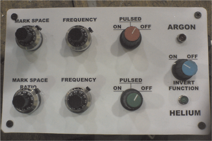
Electronic gas control unit.
A flow device (containing a diffuser and a flow straightener) was used to produce a steady, uniformly distributed, laminar cross draft at its output. The flow device was positioned such that the nozzle centre was located 300mm from the outlet and at an angle of 90° to the welding direction, as shown in Figure 2. The velocity of the cross draft was measured using a hot wire anemometer in the throat between the nozzle and plate at a height of 5mm above the plate surface. The cross-draft flow profile was calibrated at numerous velocities by measuring the velocity at 121 locations across the plate at a height of 5mm above the plate surface. Examples of the flow profiles generated are shown in Figure 3 with the cross-draft flow originating from the lower edge; as can be seen in the flow in the test region, that is, the area where the welding nozzle would be located (circle indicating the location of the welding nozzle), the flow is uniform with the flow velocity dropping rapidly ±20mm from the nozzle centreline.
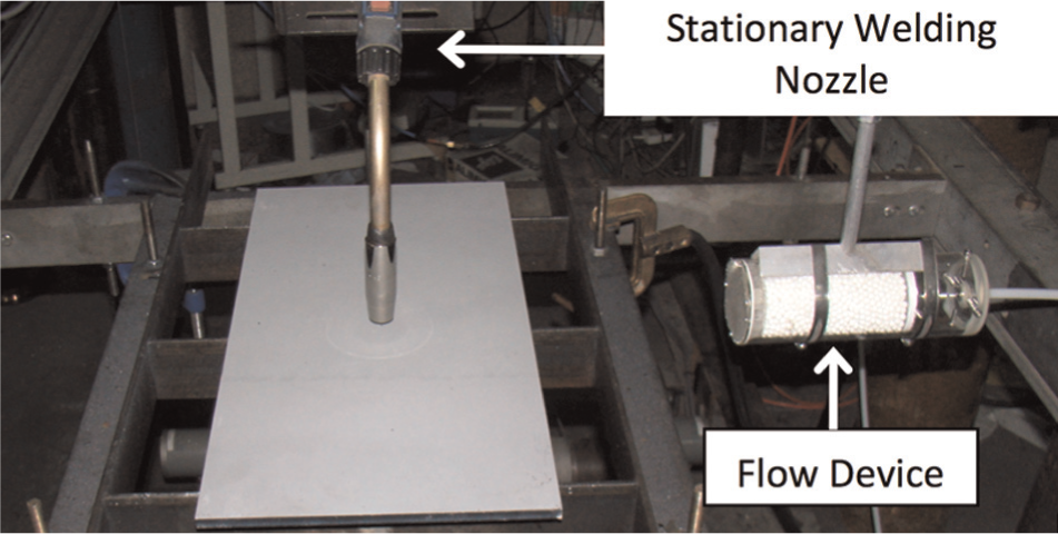
Experimental set-up showing flow device to induce cross draft.
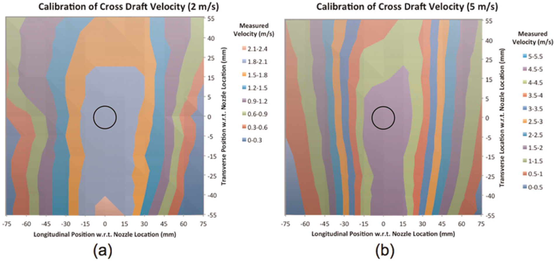
Calibration of cross draft for (a) 2m/s cross draft and (b) 5m/s cross draft.
Weld quality was evaluated using a combination of visual and radiographic examination. However, due to its ability to detect defects through the thickness of the weld, the results displayed, and consequently those used in the ANN model development, are from the radiographic examination. Due to the binary classification method employed in the ANN model, the results had to be entered in the form of pass/fail; therefore, a grading system was developed such that clean welds or welds free from harmful defects would pass and those containing harmful defects would fail.
ANN model development
The software used throughout this study was NeuroSolutions, which had previously been used by the authors for the successful prediction of weld geometry, 1 distortion 22 and distortion rectification. 24 A total of 360 datasets were produced, 36 for each nozzle and shielding gas configuration, with an additional 20 for validation/production, thus allowing for a full range of results ranging from good-quality welds performed using a low shielding gas flow rate and no cross draft, to poor quality welds with a high shielding gas flow rate and high cross-draft velocity.
Due to the nature of the problem, that is, predicting whether the weld parameters will produce a good- or poor-quality weld, a classification network was selected. The datasets were broken down so that approximately 75% were used for training the model, 10% for cross-validation, 10% for testing and the remaining 5% for production (with the resultant weld quality being withheld from the software), each dataset being assigned the same role throughout. NeuroSolutions not only indicates whether an output is a binary 0 or 1, it also indicates how accurate the prediction is, that is, 0.95 is far more likely to be a 1 than a 0, thus allowing a comparison of two different network structures with the same binary predictions.
The model generation process was conducted using the same iterative process described in previous studies. 1,22 This involved determining the model configuration that would produce the lowest percentage and mean-squared error. Throughout the model generation, each model was run three times with the average error being recorded.
The final model architecture is summarised as follows:
Model topology: multilayer perceptron;
Iterations: 8000;
Hidden layers: 1;
Momentum learning: 0.7;
Weight updating: batch.
ANN model validation and prediction
In order to ensure the validity of the model and ensure that the model had not simply remembered the data that were used to train the model, validation welds were used to test the generated models robustness and accuracy. A number of weld input parameters were selected that were within the training data range and had not previously been used in the model generation. Shielding gas flow rates of 7.5 and 12.5L/min were used to prevent the model potentially providing a previously ‘learned’ answer. The weld input variables were then entered into the ANN model, and the results were compared to radiographic inspection of the experimental weld. Table 1 presents the input parameters used, along with the ANN prediction and radiographic inspection results of these trials.
Validation weld trials showing experimental parameters, ANN prediction and radiographic assessment.
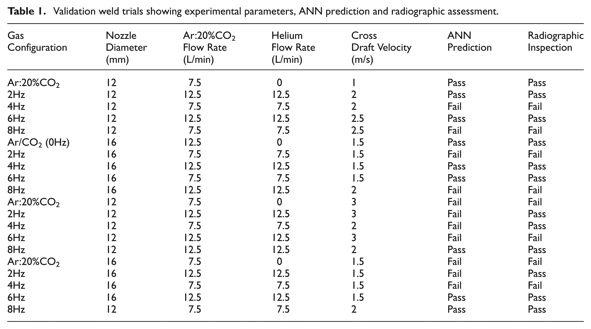
As can be seen in Table 1, the ANN model predicted 17 out of the 20 validation welds successfully. However, this prediction accuracy can be easily misinterpreted due to the location of incorrect predictions.
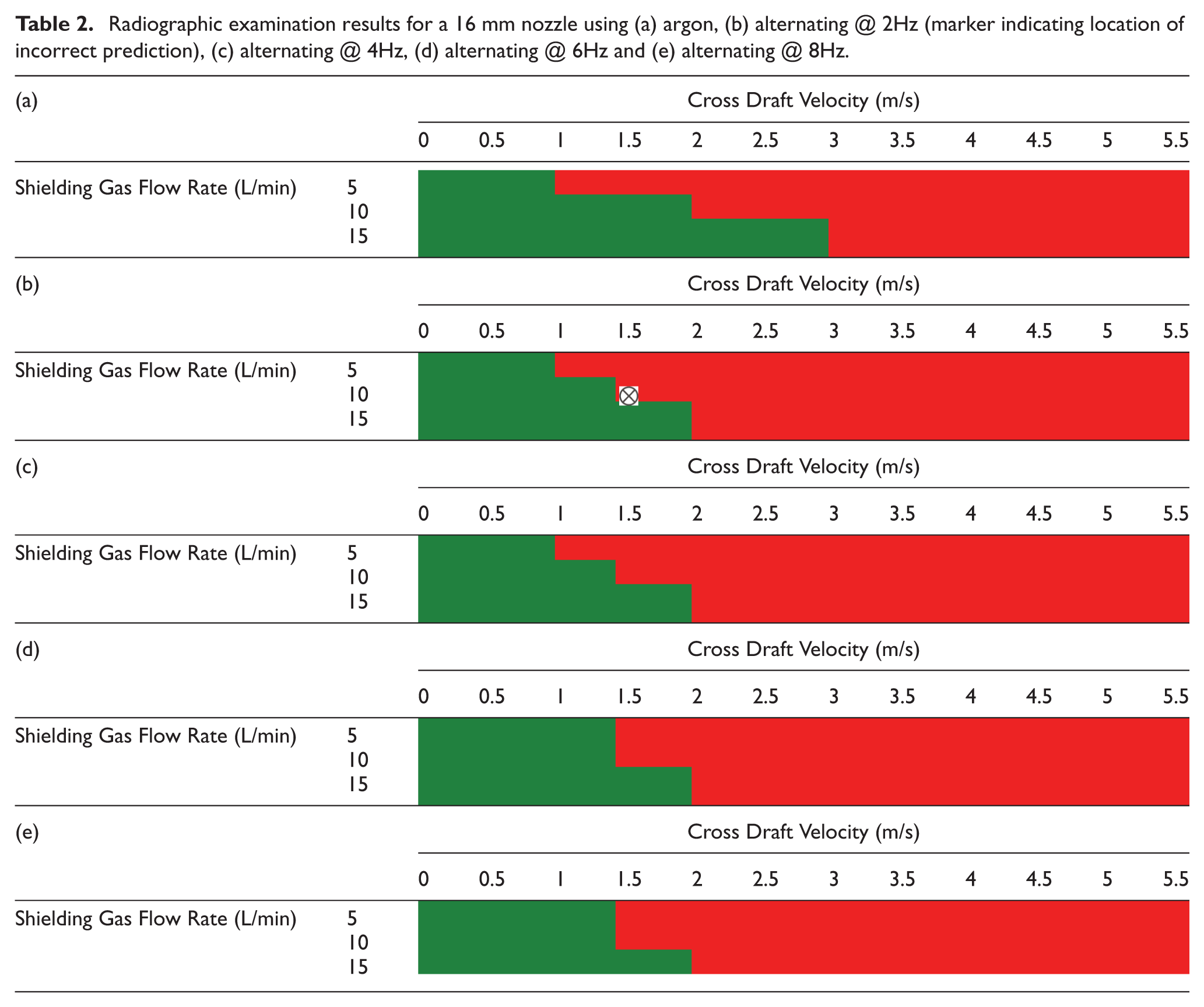
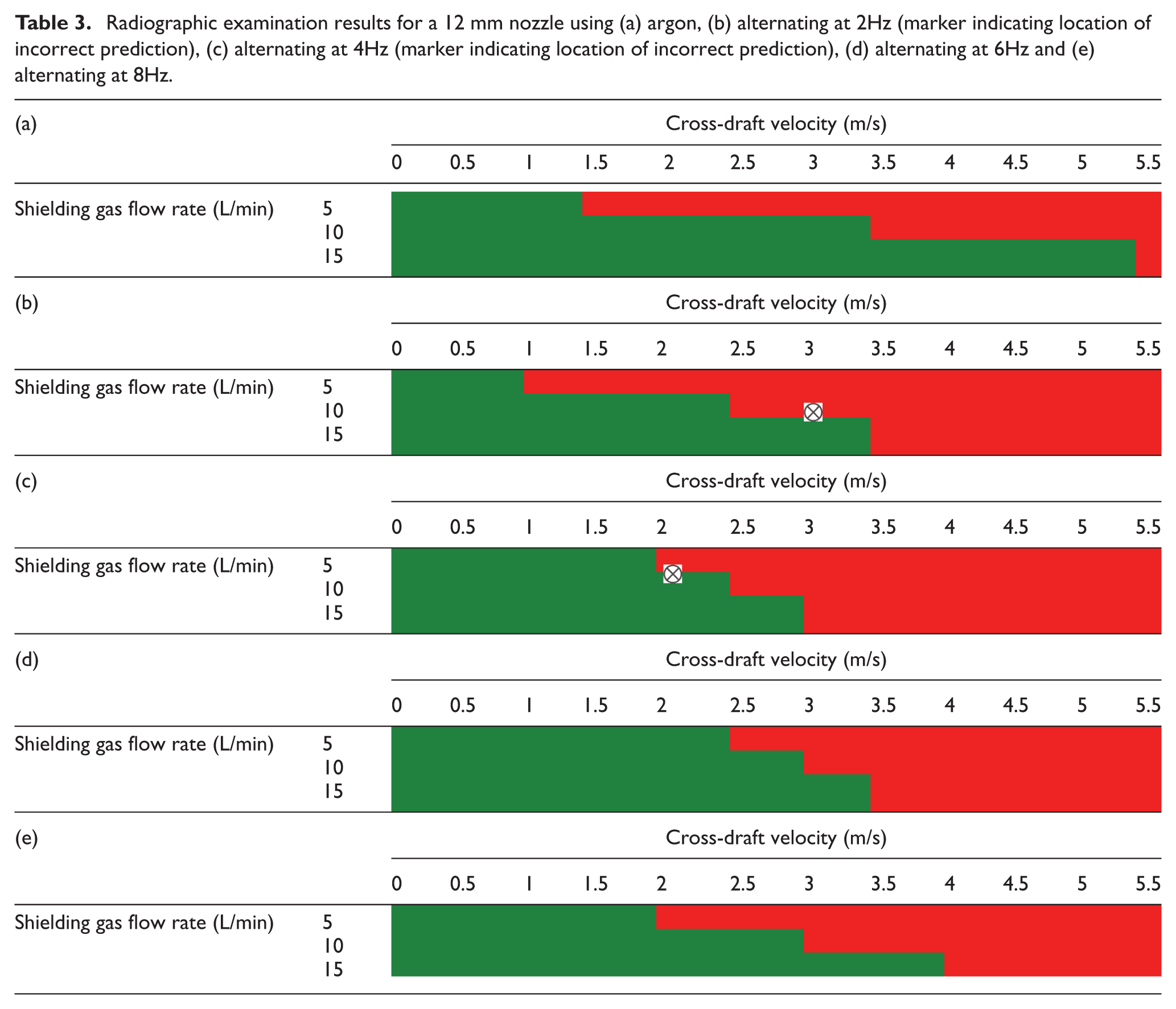
The validation welds were selected to give a spread of datasets across the shielding gas and cross-draft ranges, with particular attention being paid to the transitional region for each shielding gas configuration. This meant that the result for each dataset could not simply be read from the experimental trials and presented a far more challenging prediction for the model, while validation trials away from the transitional region have been omitted from the discussion in order to highlight the benefit of using such an ANN model to optimise welding parameters in this region. The three welds that the model incorrectly predicted are displayed in Tables 2(b) and 3(b) and (c), and, as shown, are along the good-/poor-quality transition boundary.
Radiographic examination results for a 16 mm nozzle using (a) argon, (b) alternating @ 2Hz (marker indicating location of incorrect prediction), (c) alternating @ 4Hz, (d) alternating @ 6Hz and (e) alternating @ 8Hz.
Radiographic examination results for a 12 mm nozzle using (a) argon, (b) alternating at 2Hz (marker indicating location of incorrect prediction), (c) alternating at 4Hz (marker indicating location of incorrect prediction), (d) alternating at 6Hz and (e) alternating at 8Hz.
Results and discussion
As stated previously, weld quality was assessed through the use of radiographic examination, the results of which are displayed in Tables 2(a)–(e) and 3(a)–(e). For each weld nozzle and gas configuration, there is an obvious increase in cross-drafts resistance as the shielding gas flow rate is increased. As would be expected, the lower, 5L/min, flow rate is more susceptible to the adverse effects of cross drafts, ultimately resulting in poor weld quality at low cross-draft velocities.
As in other studies, 13 –15 the narrower, 12 mm-outlet-diameter, nozzle has consistently provided better protection to the weld region when subjected to cross drafts. This is due to the conservation of mass, and therefore, the shielding gas will accelerate through the nozzle and exit at a far higher velocity than it would when using the 16-mm-outlet-diameter nozzle.
As can be noted from the experimental results, the conventional Ar:20%CO2 mixture faired considerably better than any of the alternating frequencies. In this series of trials, the Ar:20%CO2 mixture produced a cross-draft velocity to shielding gas exit velocity ratio of 2.4 and 2–2.5, for the 16 and 12 mm nozzle, respectively. However, when implementing alternating shielding gases, this ratio reduces, on average, to 2.1 and 2 for the 16 and 12 mm nozzles, respectively. The decrease in the critical ratio is believed to be the result of two combined effects: (a) alternating between two gases produces turbulence in the shielding gas column, which in a draft-free environment has no effect but when subjected to a draft encourages intermixing of the atmospheric gases to the shielding gas column, and (b) helium has a considerably lower density than air meaning it drifts rather than creating a blanket effect that the Ar:20%CO2 mixture does.
At 5L/min, alternating shielding gases have been shown to produce better protection to the weld pool. This is believed to be due to the pressure impulse, 9 which occurs due to a build-up in line pressure and is released when the valve is opened, causing an increase in the shielding gas exit velocity. Concurrently, when using conventional Ar:20%CO2, there is no pressure impulse, the exit velocity is slow and is therefore blown from the weld area before it is able to reach weld level, thus preventing the blanket effect from occurring.
When solely comparing alternating frequencies, there is very little difference in the resultant weld quality when using the 16 mm nozzle. However, with the 12 mm nozzle, as the frequency increases, the resistance to cross drafts also increases. This is mainly due to a trade-off between an impulse in pressure (lower frequencies having a longer time for pressure to accumulate) and turbulence due to the alternating process (lower frequencies creating greater turbulence). This study has shown that ANN modelling could very easily be adopted for weld quality prediction on a larger scale.
The accuracy of prediction could be enhanced further by providing a higher density of datasets for the transitional region, that is, varying the cross-draft velocity by 0.1m/s rather than 0.5m/s and/or varying the shielding gas flow rate by 1L/min rather than 5L/min. This would provide the model with a better understanding of where the weld transitioned from good to poor quality and would ultimately increase the accuracy of prediction. However, as an industrial tool, it is not expected that this level of risk would be employed and some safety factor would be used; therefore these additional data were not required.
Conclusion
From the extensive experimental trials carried out with alternating shielding gases at various frequencies, it can be seen that the alternating shielding gas process is not as resilient to the adverse effects that cross drafts introduce when compared to a conventional Ar:20%CO2 mixture. This is mainly due to the density of the helium phase of alternation; thus, the gas is far more susceptible to drifting from the weld pool.
This study has highlighted the potential to implement ANN software to help improve the efficiency of the GMAW process, through its ability to predict the quality of a weld using a specified set of inputs, thus enabling the operator to know the outcome prior to performing the weld itself. For example, should a higher cross draft be detected, the software can predict the weld inputs (nozzle diameter, shielding gas flow rate, etc.) required to produce a high-quality weld.
The ability to predict the weld quality when implementing a lower shielding gas flow rate leads to obvious benefits on an industrial scale, with studies by Campbell et al. 8 demonstrating that the shielding gas flow rate can be reduced in draft-free conditions and when a draft is present when using a conventional Ar:20%CO2 mixture. Investment in an ANN model which has been thoroughly developed and validated for the specific process it is to predict would lead not only to time and material saving, but also help reduce wastage of gas in the process itself.
Footnotes
Declaration of conflicting interests
The authors declare that there is no conflict of interest.
Funding
This study was funded by BAE Systems Surface Ships Limited.