
Abstract
Metal inert gas arc welding process was implemented to join 6063T6 wrought alloy and ADC12 die-casting alloy using ER4047 filler metal. The microstructure of the weld seam and weld interface was investigated. The bonding strength of the butt joints was tested by Charpy U-notch impact test and tensile test. The results showed that a sound welding butt joint with finely silicon particles and excellent mechanical properties was formed, and the size of the silicon particles was nearly 2 μm. Compared with 6063T6 wrought alloy, the impact absorbing energies and the tensile strengths of the butt joint were higher and reached 1.173 kJ/cm2 and 205 MPa, respectively, and the fractures of all tensile specimens occur at the 6063T6 aluminum.
Keywords
Introduction
With the demand for lightweight cars, the use of aluminum alloy instead of steel in construction of car bodies can reduce CO2 emissions, energy and fuel consumption,1,2 owing to its low density and high specific strength. 3 In the past few years, the hybrid structures of wrought aluminum alloy and stainless steel have shown great potential in applications, so many researchers focus on the joint problem of aluminum alloy and stainless steel.4,5 Although this hybrid structure has already become the typical design to achieve light weight in a number of industries, such as automobile, aircraft and shipbuilding,6,7 with the rapid development of electric vehicles, more and more load-bearing parts are produced by casting aluminum alloy instead of steel, especially die-casting aluminum alloy. Thus, dissimilar aluminum alloy joint technologies are needed, in particularly the welding of aluminum alloys fabricated in different forming ways. However, conventional studies of welding dissimilar aluminum alloy have always focused on different wrought alloys or casting alloys and research on joining casting aluminum and wrought aluminum alloys have been very few.
Moreover, most of the investigations for joining dissimilar aluminum alloys have been carried out by friction stir welding (FSW).8–11 In FSW, welded joints are obtained quickly and reliably without any heat supplier, wherein the required temperature for joining is generated by means of a revolving pin which moves along a proper trajectory partially sunk in the workpiece surface between two base metals.12,13 Although the FSW method is known to be a very suitable technique for welding of aluminum alloys, it is still difficult to realize butt joining of aluminum automobile parts which have a complex structures or are thin-walled, because the shape and size of FSW joints are extremely restricted, 14 the capital equipment costs of FSW are very high 15 and the procedures of FSW are very complex.16,17
Hence, for the automobile parts mentioned above, the most common joining method remains fusion welding, such as metal inert gas (MIG) welding, widely used in industrial welding of aluminum alloys. Compared with the FSW method, MIG welding is suitable for a wide range of plate thicknesses, and has other benefits including high-energy utilization, 18 easy operation 19 and relatively high productivity.
In this article, MIG arc welding is applied to join 6063T6 wrought aluminum alloy and ADC12 die-casting aluminum alloy, and the appearance, microstructure, impact properties and tensile properties of the joint formed by the MIG method are experimentally investigated.
Experimental procedure
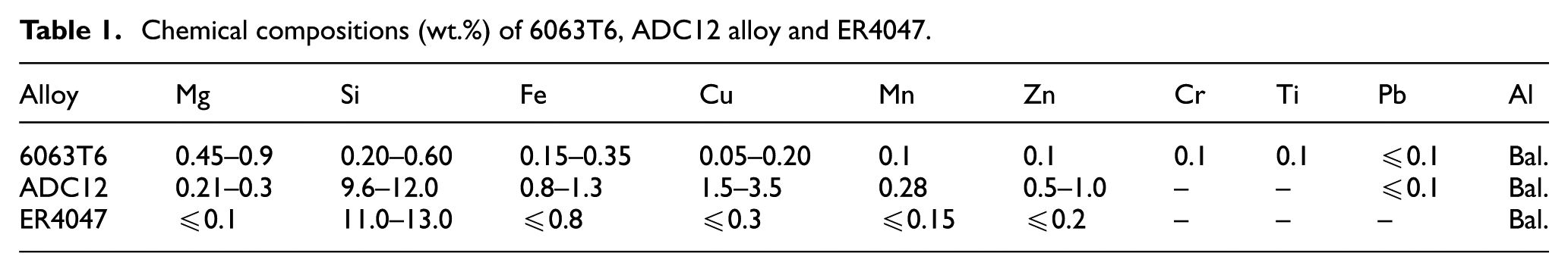
Two typical aluminum alloys for automobiles, 6063T6 wrought alloy and ADC12 die-casting alloy, were employed as the base metals in this article, and ER4047 wire with a diameter of 1.2 mm was used as the filler metal. Table 1 lists the nominal chemical compositions of ADC12 and 6063T6 aluminum alloy, as well as the filler metal. The dimensions of the plates were 200 × 70 × 15 mm3. The V-type welding groove was prepared by milling and the groove angle of each aluminum alloy plate was 45°, as shown in Figure 1(a). The surface of the welding groove was processed chemically prior to MIG welding. The placement angle between the two plates was 170° for backward deformation, as shown in Figure 1(b). The cross section of work piece is shown in Figure 1(c). The MIG welding experiments were implemented by TransPuls Synergic 4000 MIG welding machine, shown in Figure 1(d). Argon was used as shielding gas for MIG, and the argon flow rate was 10 L/min. The wire feed rate was maintained at 2 m/min, and the pulse current was 180–200 A.
Chemical compositions (wt.%) of 6063T6, ADC12 alloy and ER4047.
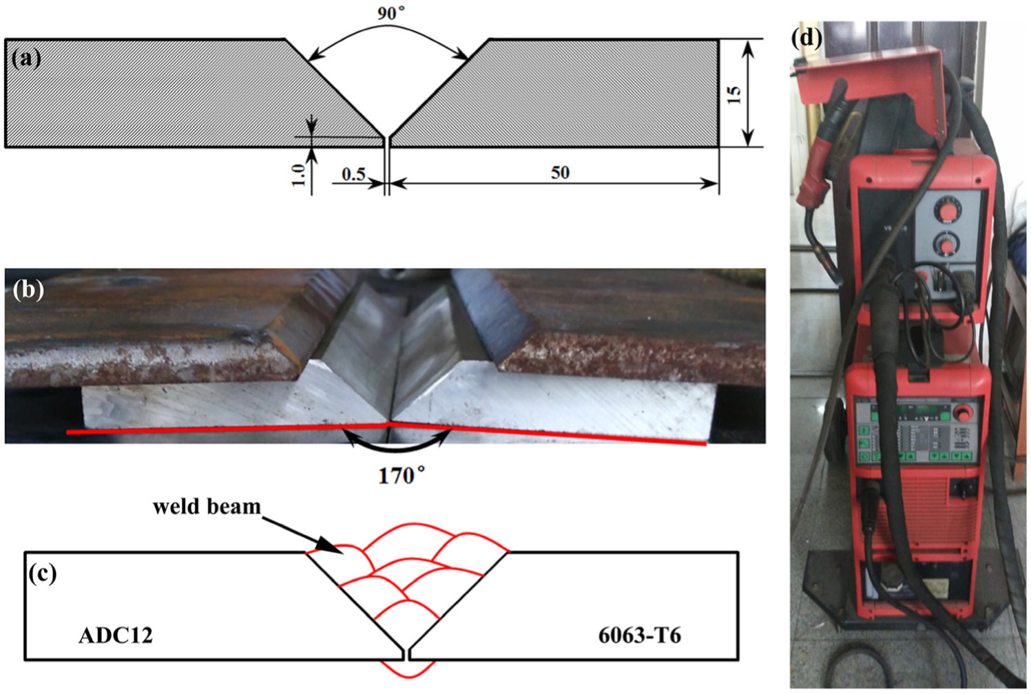
Cross section of workpiece and MIG welding equipment. (a) MIG welding groove. (b) The placement of aluminum alloy plates. (c) Weld pass for MIG welding. (d) MIG welding equipment.
Typical transverse sections of the joints were observed by optical microscopy (OM) and scanning electron microscopy (SEM). The composition of the interface between the weld metal and 6063T6 was determined by energy dispersive X-ray spectroscopy (EDS). The joint mechanical properties of ADC12/6063T6 were evaluated by tensile tests using an Instron-5569, a 50 kN universal testing machine, with a constant cross-head speed of 1.0 mm/min at room temperature. The tensile test specimens with 85 × 10 × 2.5 mm3 and the Charpy U-notch impact test specimens with 55 × 10 × 10 mm3 were obtained perpendicular to the welding direction by electrospark wire-electrode cutting. At least five specimens were tested and the values reported were the average of at least three good reproducible results.
Results and discussion
Appearance and macrostructure
A continuous and uniform surface of welded seam is exhibited in Figure 2(a) with no cracks, and a good front formation obtained on the weld surface can be seen in Figure 2(b) as well as the back. The cross-section appearance of ADC12/6063T6 aluminum alloy butt joint is shown in Figure 2(c), while Figure 2(d) displays the OM photograph corresponding to the box in Figure 2(c), the eutectic Al-Si filler metal fused fully on both side of base metal surface to form a sound joint. In the ADC12 alloy side, the fusion zone has a blurred boundary on account of similar main compositions of ADC12 alloy and ER4047, thus the eutectic Al-Si base metal with a low melting point (about 580 °C) would mix with the molten filler wire to form a fusion zone. While in the 6063T6 alloy side, the surface with slight silicon content and a slightly higher melting temperature (about 620 °C) resulted in the clear interface layer, which is observed like a brazing joint.
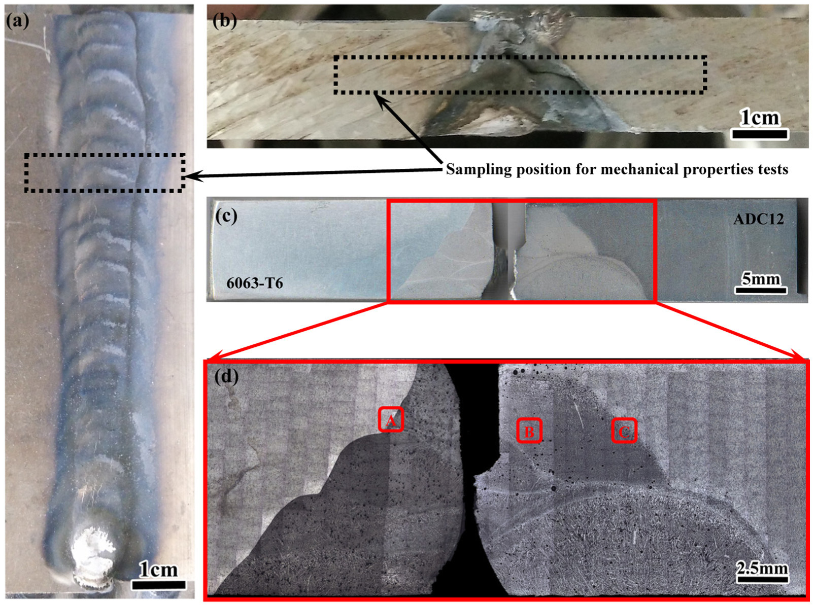
Appearances and cross section of the ADC12-6063-T6 aluminum alloy butt joint. (a) and (b) The joint face. (c) and (d) The joint cross-section.
Microstructure
Figure 3 shows OM and SEM images in different areas of the joint marked in Figure 2(d). A clear and smooth boundary along the welding groove with a 45° angle approximately can be observed, as marked in yellow in Figure 3(d), being a large difference in silicon content between 6063T6 alloy and welded seam. For MIG arc welding heating, the welding heat input is large and smooth, 5 thus the primary α-aluminum matrix can fuse well between 6063T6 and welded seam along the boundary. On the other hand, the silicon rarely has time to diffuse into molten 6063T6 alloy because of the rapid heat output on both sides of the joint. Hence, most of the eutectic silicon is formed on the welded seam side. Furthermore, there are no obvious heat affect zones (HAZ) be found in both the base metals in Figure 2(d). In order to identify the size of the diffusion layer of silicon, the EDS analysis was carried out, as shown in Figure 3(g) and (h). According to the changes in magnesium and silicon content along the line shown in Figure 3(g), the thickness of diffusion layer between welded seam and 6063T6 is less than 8 μm.
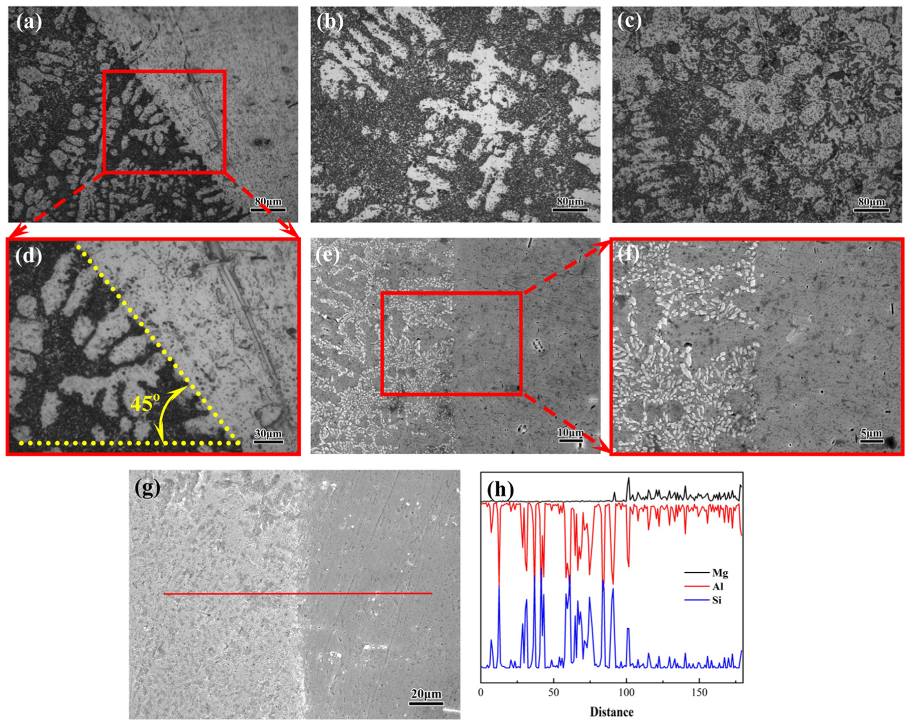
OM and SEM images in different positions of the ADC12/6063T6 joint. (a) and (d) Fusion area in A zone. (b) Welded seam in B zone. (c) Fusion area in C zone. (e), (f), and (g) SEM images of fusion area in A zone. (h) EDS result of the line in (g).
And, more remarkable, from zone C in Figure 2(d), the welded seam seems darker under the contrast of the OM than the ADC12 alloy, which has similar silicon content. It is actually caused by the different morphology of the eutectic silicon on both sides of the border. The eutectic silicon exists in ADC12 alloy mainly in block form, and dispersive distributed in the entire welded seam in rounded particles as shown in Figure 3(c). The average size of the eutectic silicon particles in welded seam is nearly 2 μm, which can be observed from the SEM results illustrated in Figure 3(e) and (f). Different from the metallurgy and solidification process of casting, as mentioned above, the welding heat input and output are both more rapid in welded seam, thus the rapid heating will result in incomplete melting of the block-like eutectic silicon that cause the block-like eutectic silicon fusion and become smaller and round. In addition, a high cooling rate can increase the nucleation rate of the molten eutectic silicon, and restrict the growth of eutectic silicon. Finally, the fine and dispersedly eutectic silicon particles will be obtained in the entire welded seam.
Mechanical properties
The Charpy U-notch impact tests and tensile tests are carried out to measure the joint strength and behavior, and all the specimens for mechanical property tests are cut and machined from the position as marked by the dotted box in Figure 2(a) and (b). The average of impact absorbing energies of the butt joint is akU = 1.173 kJ/cm2. The average of tensile strengths of the butt joint reaches 205 MPa and the fracture of all specimens occur at the 6063T6 aluminum. The Charpy U-notch impact tests of 6063T6 alloy are also conducted for reference and the impact absorbing energy is akU = 1.08 kJ/cm2.
Conclusion
In this study, MIG welding of 6063T6 wrought alloy and ADC12 die-casting alloy plates with ER4047 solder wire was performed, and the following conclusions were drawn:
Sound welding butt joints are obtained with the fine and dispersedly eutectic silicon particles in entire welded seam, and the average size of eutectic silicon particles is nearly 2 μm. Moreover, no obvious HAZ is observed in both the base metals.
A clear and smooth boundary along the welding groove between 6063T6 alloy and welded seam is caused by their different silicon contents. The thickness of diffusion layer of silicon at this boundary is less than 8 μm.
The impact absorbing energies of the butt joint reached 1.173 kJ/cm2 and their tensile strengths were 205 MPa. In addition, the fractures of all tensile specimens occur at the 6063T6 aluminum, thus, the mechanical properties of butt joint are higher than that of 6063T6 aluminum alloy.
Footnotes
Declaration of conflicting interests
The author(s) declared no potential conflicts of interest with respect to the research, authorship and/or publication of this article.
Funding
The author(s) received no financial support for the research, authorship and/or publication of this article.