
Abstract
Droplet formation characteristics of molten caprolactam, the monomer of nylon 6, are reported in this article as part of research to develop a novel inkjet additive manufacturing process. Initial investigations confirmed the jettability of molten caprolactam at 80 °C with a printhead and recommended a range of parameters for a stable jet array. High-speed imaging was used to study the interactions between the melt and the printhead. Droplets were generated at voltages higher than 12.5 V. Nozzle wetting and crosstalk in adjacent nozzles were observed especially at higher voltages. Jetting frequency did not affect the droplet characteristics. By varying the jetting voltage though significant changes to the droplet shape, evolution and kinetics were observed. Satellite droplets were formed by disintegration of the tail at lengths of about 1 mm when a jetting voltage of 25.0 V was used. An increase of voltage from 15.0 V to 25.0 V increased the droplet velocity from 2 m/s to 8 m/s. Reynolds and Weber numbers predicted there would not be splashing upon droplet impact, which was confirmed by experiments when impinging molten caprolactam droplets on cold and heated substrates. The droplet formation study suggested a set of jetting parameters to be used for the next stage of the research on the inkjet process development.
Introduction
Inkjet additive manufacturing
Additive manufacturing employs a variety of techniques including inkjet printing to fabricate layers on top of each other to build a three-dimensional (3D) object. The tool-free concept of adding layers for fabrication of complex objects from computer-aided design (CAD) models within a few hours has gained interest in many applications, including aerospace, automotive, medicine and sport. 1 There has been ongoing research into new technologies that can deposit multiple materials in one process and obtain higher functionality from the manufactured parts and enhanced process resolution.
The significant progress of inkjet technology since the 1990s has resulted in reducing the droplet size and increasing the deposition resolution, throughput rate and operating temperature for faster and cheaper printers for the graphics applications. 2 As a result, a rapid growth in research of non-graphical use of this technology has been seen to deposit a wide range of materials, including polymers, ceramics, metals and even living cells in form of diluted solutions, suspensions and melt, on various substrates in a precise and controlled manner.3–7 Additive manufacturing processes have been successfully commercialised based on inkjet printing of molten waxes and ultraviolet (UV) curable resins. Examples are the Multi-Jet Modeller (MJM) technology from 3D Systems introduced in 1997 and PolyJet technology from Objet Geometries in 2001, respectively. 1
Inkjet technology
Inkjet technology has been classified into two main printing modes based on the jetting head used: continuous and drop-on-demand (DoD). 2 In the continuous mode, the ink is pressurised through a feeding system and then by vibrating a piezoelectric element, a train of droplets is made. The droplets either impinge onto a substrate or enter into a circulation system (a gutter) by two deflection plates to provide control over selective deposition of material onto the substrate. In a DoD mode inkjet printhead, a voltage signal is sent to a transducer, made mainly of piezoceramic elements, which actuates to force liquid material out through a nozzle and form a droplet to hit the substrate. The voltage signal is sent when a droplet is needed, and therefore, compared with the continuous mode, there is no need for the droplet deflection and ink recirculation units resulting in a less complex system.
Several physical properties of a liquid contribute to the droplet formation process, from pressure wave propagation inside the nozzle to break-up of a droplet in DoD piezoelectric printheads.3,8 Viscosity, surface tension, density and particle size are the most critical properties for jettability of a material. There is a threshold voltage amplitude after which a droplet is formed. This is because of viscous dissipation of the compressible liquid during the pressure wave propagation upon transducer actuation. 2 Depending on the actuation voltage signal and the physical properties of the fluid, a droplet can be jetted either with or without a tail that can disintegrate into smaller satellite droplets. Upon each nozzle actuation, there will be some residual pressure wave inside the ink channel that could interact with the next actuation and diminish the droplet generation consistency. This limits the maximum jetting frequency of a printhead. Complex waveforms have been designed to surpass the residual pressure waves and so increase the maximum jetting frequency by up to three times. 9
Jetting of nylon
Most polymers are too viscous in their liquid state to jet owing to their entangled long molecular chains; however, they can be jetted as a dilute solution or a colloidal dispersion. 3 The challenge though remains in functionality of the parts produced. There is a need for an additive manufacturing technique to produce parts from a functional polymer with high resolution and good surface finish. Inkjet technology could fill this gap with nylon 6; however, nylon 6 in the melt state has such a high viscosity that it cannot be jetted. As it can be polymerised from mixtures of low viscosity caprolactam at elevated temperatures, the idea of ‘jetting of nylon’ is a possibility that has been initiated. 10
The polymerisation concept is similar to the cast nylon process, but instead of premixing of the two reactive mixtures consisting of caprolactam and activator as A and catalyst as B, they could be deposited via inkjet printing. By depositing layers of the two reactive mixtures on top of each other onto a substrate, the two mixtures were expected to mix and start the reaction under appropriate conditions. This could produce nylon 6 as a solid layer before fabricating the next layer in an additive approach.
Motivation and objectives
Compositions of appropriate sets of caprolactam mixtures for a fast reaction have been investigated in parallel research. 11 Initial investigations confirmed that stable jetting of molten caprolactam could be achieved at 80 °C using a graphics industry piezoelectric DoD printhead. 10 A range of jetting parameters was recommended within a stable process window. This article though, reports on the droplet formation characteristics such as size, shape and kinetics to finalise the appropriate set of parameters for the deposition stage. In addition, interactions between the melt and the nozzle plate including the wetting behaviour are also discussed, as it could affect the separation of the droplets from the nozzle and the consequent droplet placement accuracy. Finally, impact behaviour verification of the chosen jetting parameters for a splash-free droplet deposition onto a solid surface is presented.
Experiments
Jetting material
Caprolactam was supplied from Sigma Aldrich GmbH as granules in sealed containers. It is white in the solid state but melts at 68 °C and is colourless when molten. 12 The physical properties of caprolactam were characterised in selecting the appropriate printhead and the design of the experimental setup. 10 The jetting temperature was chosen to be 80 °C at which molten caprolactam had a dynamic viscosity of 9 mPa s at shear rates higher than 100 s−1 measured by a rheometer (MCR101 – Anton Paar Ltd). The surface tension was also found to be 35 mN/m measured at 80 °C using the pendent drop method (OCR 20 – DataPhysics GmbH).
Experimental setup
Considering the physical properties of molten caprolactam, a Xaar XJ126 piezoelectric DoD printhead and its electronic peripherals, known as Xaar XUSB, were selected. The printhead had 126 nozzles of 50 µm diameter in an array of 17.2 mm width that gave a nozzle pitch of 137 µm. Maximum jetting voltage and frequency were 40 V and 5.2 kHz, respectively. The nozzle actuation in the printhead could be controlled by software through the electronic peripheral to address individual nozzles, as well as the full nozzle array. The jetting assembly consisted of a melt supply unit with thermal and pneumatic control, printhead with heaters, mount plate, fixtures and tubing as described by Fathi et al. 10
A digital microscope camera (Dino Lite AM211, ANMO Electronics Corp.) was used for monitoring the nozzle plate and record instabilities of the jet during trials. For droplet characterisation, a high speed camera (FASTCAM APX-RS, Photron Inc.) with a long lens (12X Zoom, Navitar Inc.) was used in combination with an intensive light source (ELSV-60, Everest VIT), placed opposite to the camera lens for backlight imaging. Figure 1 shows how the microscope and high-speed cameras were positioned in relation to the printhead. The high-speed camera was set at an imaging rate of 10,000 frames per second (fpm) and an exposure time of 4 µs to capture the meniscus oscillation and droplet formation on the actuating nozzle. Images from the high-speed camera were analysed quantitatively with software (measureIT, Olympus UK Ltd.).
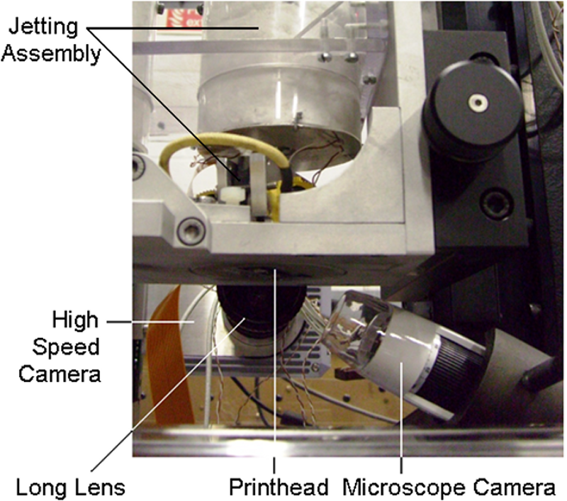
Digital microscope camera and high-speed camera positions.
Experimental procedure
A solid cartridge of caprolactam was inserted into the melt supply unit. By setting the jetting assembly at 80 °C, the solid cartridge melted and stabilised before feeding to the printhead through the filtration unit. An initial pneumatic pressure was used in the jetting assembly to feed the printhead with melt. As soon as dripping of the melt from the printhead was observed, a vacuum was applied continuously through the melt supply system to stop the dripping and retract the melt into the printhead to control the melt meniscus on the nozzles. The nozzle plate was cleaned with a lint-free cloth to remove contamination and also provide a dry nozzle plate for better observation of the meniscus oscillation and droplet formation in the actuating nozzle. The system was given at least 5 min to stabilise before jetting.
The parameters to produce a stable array of molten caprolactam jets were investigated by monitoring the nozzle plate using the digital microscope camera and recommendations were reported by the authors. 10 The variables for jetting were the voltage signal for droplet generation and the vacuum level. For the voltage signal, the amplitude and frequency could be varied, whereas the waveform and pulse width of the actuation signal were fixed by the printhead manufacturer. Figure 2 shows a stable trial with 126 jets of molten caprolactam. The range of chosen jetting frequency did not affect the jet array stability as the jetting voltage amplitude and the vacuum level were the main factors (further details could be found in the report by Fathi et al. 10 ). Figure 3 shows the recommendation for the stable range of parameters.
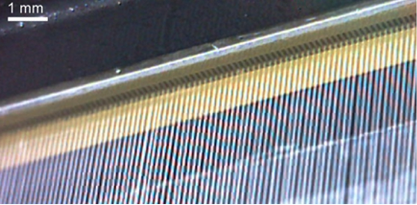
Jet array of melt caprolactam (17.5 V, 5 kHz, 25 mbar. (With kind permission from Springer Science+Business Media 10 )
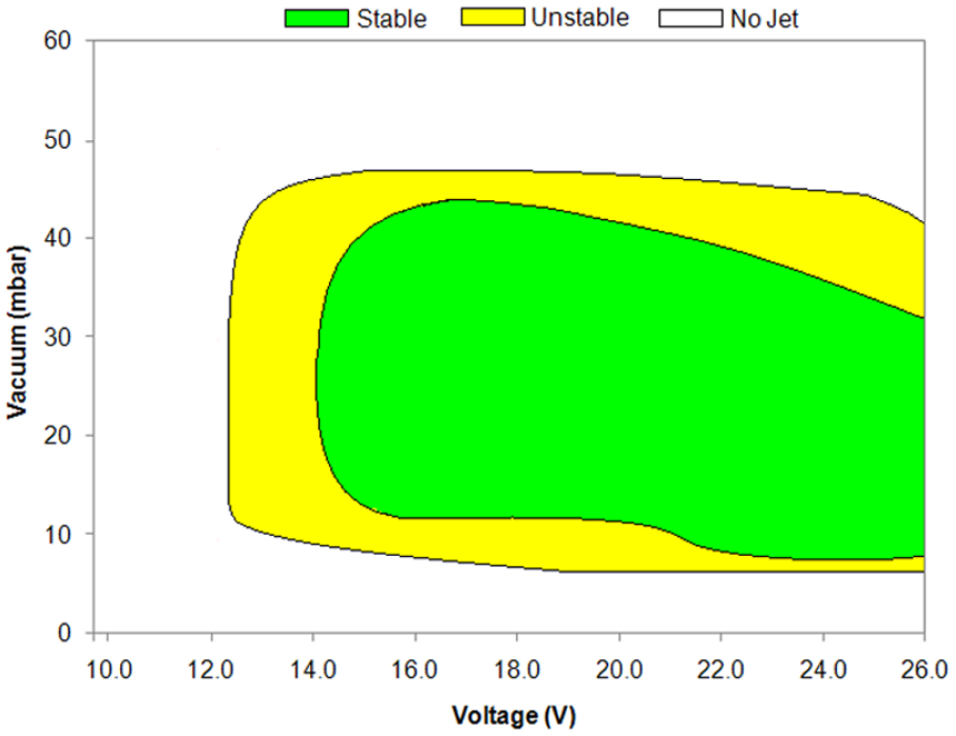
Guideline jetting parameters for caprolactam at 80 °C. (With kind permission from Springer Science+Business Media 10 )
For studying droplet formation behaviour, the vacuum level was chosen to be 25 mbar (as being in the middle of the stable range) and jetting voltage and frequency were varied from 10.0 V to 25.0 V (2.5 V increments) and 1 kHz to 5 kHz (1 kHz increments), respectively. Although the jet array stability results indicated that no jet was observed with 10.0 V and 12.5 V, it was not clear whether this was owing to immediate jet failure. Although it was found that the jetting frequency did not affect the jet array stability, its effect on the droplet formation characteristics and also nozzle wetting were studied.
The high-speed camera enabled the system to capture about 3 s of each experiment. The printhead was triggered for jetting after imaging started to record the formation of the first few thousand droplets. The images were analysed to characterise droplets after 600, 1800 and 3000 droplets were ejected. The main error in the image analysis was from the droplet edge definition, which gave ±1 pixel accuracy (the matching pixel size was about 5 µm).
Droplet characterisation
From images obtained via the high-speed camera, the evolution in the shape of the droplets, from separation to the tail disintegration, was quantitatively analysed in addition to the droplet size and velocity. For the velocity, the distance that the droplet centre travelled was extracted from two consecutive images for which the elapsed time was known from the imaging frequency. As the distance between the substrate and the nozzle plate was recommended by the printhead manufacturer at 1 mm, the droplet characterisation was undertaken at this distance (±100 µm, depending on the position of the droplets in the image frames). The droplet kinetic energy was calculated from droplet size, velocity and the physical properties, as were the Weber and Reynolds numbers (the main dimensionless numbers widely used to predict the impact behaviour of droplets 13 ).
The aim was to have stable and consistent droplet formation and splash-free droplet spreading (to form uniform beads). Therefore, verification experiments on impact behaviour of molten caprolactam on a solid substrate at the chosen settings were also undertaken. A stationary microscope glass slide (Gerhard Menzel GmbH) was used as the deposition surface. The glass slide was fixed to a thermally controlled aluminium substrate and experiments were undertaken at room temperature (20 ± 1 °C) and also 80 ± 3 °C.
Results and discussions
Meniscus oscillation and droplet formation
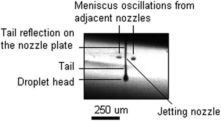
Oscillation of the melt meniscus was observed at the actuating nozzle, even with jetting voltages as low as 10.0 V, and with all frequencies as Figure 4 shows. It is also seen in the figure that the oscillating meniscus (seen as a dark spot) had a reflection on the nozzle plate. Another feature of the figure is that no spot was seen for the adjacent nozzles. Considering the viewing direction and the magnification, the image was expected to cover at least five nozzles in the frame (the nozzle spacing was 137 µm). This suggests that the meniscus for the adjacent nozzles was inside owing to the vacuum level used. The image shown in Figure 4 was taken after hundreds of nozzle actuations and the dark strip around the oscillating meniscus was the wetting area that occurred for all experiments.
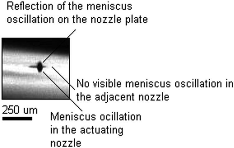
Meniscus oscillations in the actuating nozzle at a low jetting voltage (10.0 V, 5 kHz).
The high-speed microscopic imaging showed that the meniscus oscillation with 10.0 and 12.5 V did not form a single caprolactam droplet at all jetting frequencies. Therefore, the lack of jet in the jettability trials 10 was not from an immediate jet failure with these voltages. It was assumed that the pressure wave transferred to the meniscus upon the nozzle actuation was not adequate to overcome the surface tension forces on the melt meniscus to expel a droplet. This could be owing to small changes of the ink channel in generation of the pressure wave amplitude or high level of dissipation during propagation because of the compressible liquid. Another consideration would be the negative residual pressure wave from previous actuation that could surpass the oncoming (positive) pressure wave as reported in literature. 9
Jetting voltages, equal to and higher than 15.0 V, formed a train of droplets at all jetting frequencies. Figure 5 shows a droplet of the molten caprolactam being ejected. Before the droplet separated from the nozzle, a tail formed, which was attached to and travelled with the droplet. This was the same for all jetting parameters that could generate droplets. The tail attached to the droplet disintegrated into small satellite droplets with voltages higher than 17.5 V. The tail evolution will be discussed further in the section on ‘Droplet shape evolution’.
High speed imaging of a droplet being ejected from a nozzle (15.0 V, 3 kHz).
Two small spots around the actuating nozzle are also seen in Figure 5. They were meniscus oscillations on the adjacent nozzles made by the actuation. From the adjacent nozzle positions and the reflection of the tail on the nozzle plate, the exact position of the actuating nozzle was determined. Figure 6 also shows how the meniscuses of the adjacent nozzles behaved during droplet formation with a high voltage of 25.0 V at 3 kHz. The situation prior to nozzle actuation is seen in Figure 6(a) where all channels were at rest (t = 0 ms). Figure 6(b) is after jetting started when the meniscus of the adjacent nozzles vibrated before the droplet was expelled. In the next frame (after a further 0.1 ms in Figure 6(c)), there is a droplet with a long tail separated from the nozzle. Figure 6(d) shows the jetting and adjacent nozzles having returned to their initial (rest) form. The meniscus oscillation to the droplet separation took less than 0.2 ms as seen in Figure 6.
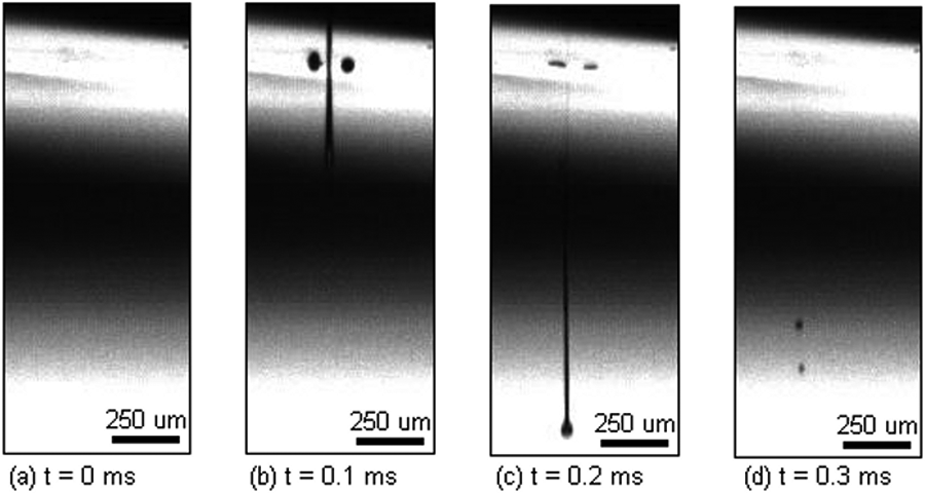
Meniscus oscillation in the adjacent actuating nozzles due to the shared wall technology used in the printhead (25.0 V, 3 kHz).
The structural design of the printhead shared each channel’s walls with the adjacent channel. This technology was patented and known as ‘shared wall’ by Xaar plc. 2 With a voltage signal, the channel walls of an actuating nozzle vibrated to expand and contract the melt channel to generate a droplet. With the shared wall technology, the adjacent channels were also affected making a partial expansion and contraction. This, consequently, resulted in the meniscus oscillation on the adjacent nozzles as seen in the form of dark spots around the jetting nozzle in Figure 6(b) and (c). The meniscus oscillation made by the partial actuation is also known as ‘crosstalk’, 14 which could affect the jet stability by influencing wetting. With higher voltages, the meniscus oscillation on the neighbouring nozzles from the partial actuations increased in size, however, no droplet was expelled with the partial actuation.
The nozzle wetting during the droplet formation process is important as it could interact with the droplet formation stability (e.g. by asymmetric wetting). With the dry nozzle plate, a wetting area developed over time around the actuating nozzle. This phenomenon was observed in all the parameter settings. Figure 7 compares the actuating nozzle before and after the wetting area developed. Figure 7(a) shows the start of jetting with no residual melt on the actuating nozzle and only the meniscus oscillation of the adjacent nozzle visible. On the other hand, Figure 7(b) shows the wetting area after ejection of 3311 droplets at 25.0 V and 3 kHz. The wetting area is seen as a dark strip because the camera was slightly angled from the horizontal position (a side view) to capture this. Meniscus oscillation and the lower surface tension of the jetting materials, compared with the nozzle plate, were responsible for the development of the wetting area. With each actuation, a small amount of melt was left on the nozzle plate. This resulted in propagation of the wetting area and its expansion over time as seen in Figure 7(b). Figure 8 summarises the observations made in droplet formation experiments.
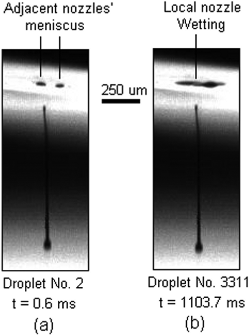
Nozzle wetting after ejection of (a) 2 droplets, (b) 3311 droplets (25.0 V, 3 kHz).
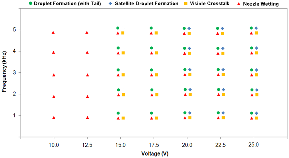
Summary of observations in droplet formation experiments.
Droplet shape evolution
Within the range of parameters, all droplets of molten caprolactam were accompanied with the formation of a tail, as typically shown in Figure 5. This was because, with the meniscus oscillation high enough to overcome the surface tension forces on the meniscus curvature, necking occurred between the melt being expelled and the remainder of the melt in the nozzle. Analysis of the high-speed imaging showed that varying jetting frequency within the range did not affect the droplet shape or the tail size. However, the tail formation characteristics varied with the jetting voltage. Figure 9 shows the tail length for low and high-jetting voltages. As seen, the tail length was measured just after the separation from the nozzle. Results for tail length versus jetting voltage are shown in Figure 10. Increasing the voltage produced greater oscillation of the melt meniscus and, therefore, a larger amount of melt was ejected, which resulted in the formation of a longer tail with the droplet.
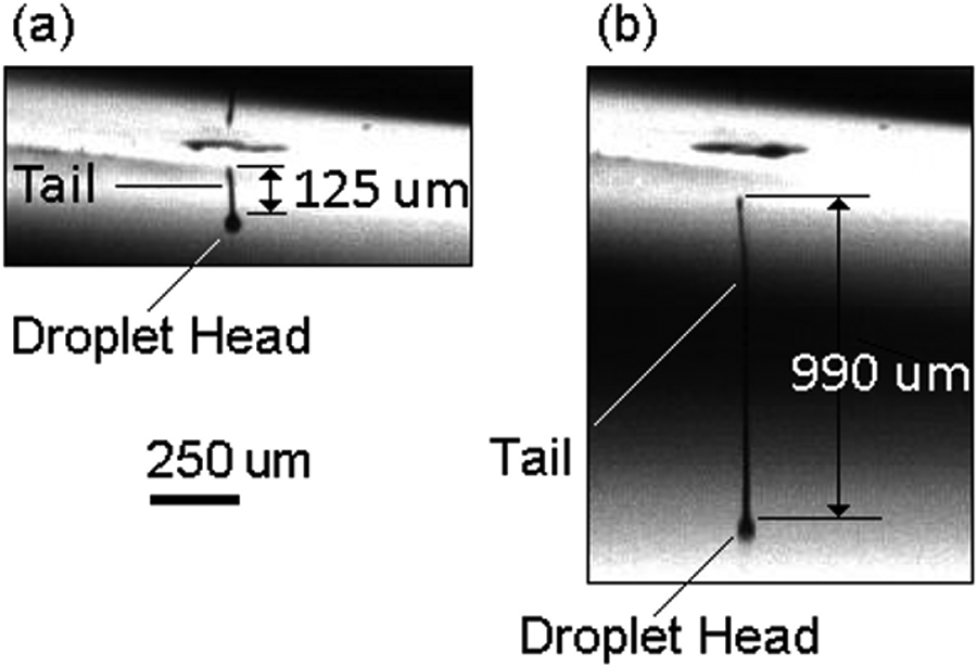
Tail length measurements after separation (a) 15.0 V and 3 kHz, (b) 25.0 V and 3 kHz.
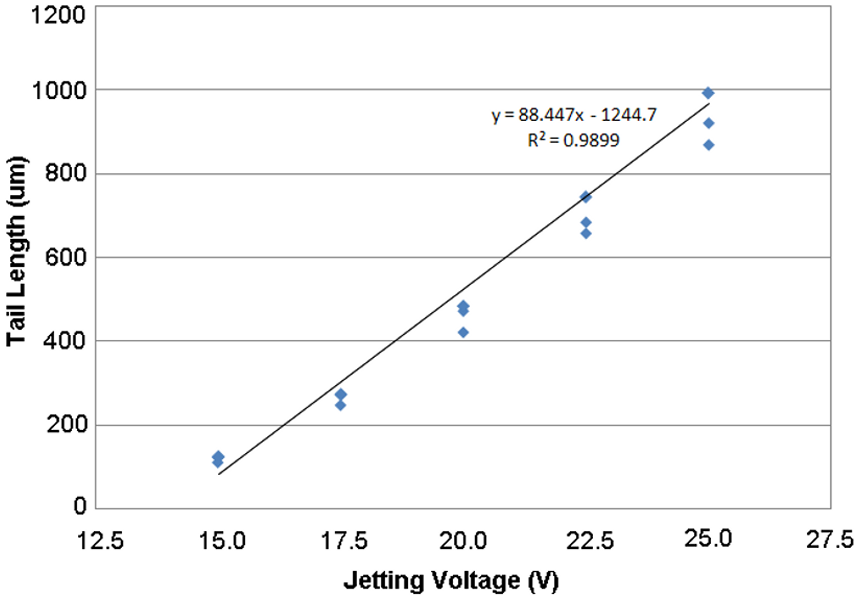
Tail length versus voltage when jetting of molten caprolactam (3 kHz).
Figure 11 shows the evolution of a droplet with a tail and also demonstrates the meniscus oscillation in the adjacent nozzles. In Figure 11(a) and (b), the meniscus oscillations from the partial actuations are seen. After 67 µs, as seen in Figure 11(c), two further adjacent nozzles on both sides of the ejecting nozzle were also partially actuated. Figure 11(c) also shows the situation just before the tail separated from the nozzle. It is seen that the tail end became thinner than the nozzle diameter (50 µm) owing to necking just before separation. This supports the suggestion that the meniscus was inside the nozzle. It is also seen that the tail thinning was deflected to one side, which could have been the result of separation from the rest of the melt inside the nozzle and then touching the nozzle edge. A similar situation was reported by Hutchings et al. 15 when graphical ink at room temperature was jetted. The deflected tail end can be seen in Figure 11(d). The tail end deflection was repeatable within the range of jetting voltages and frequencies.
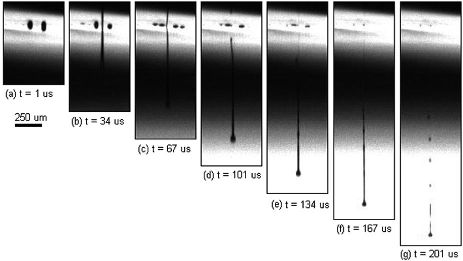
Evolution of a tail (formation and disintegration) (25.0 V, 3 kHz).
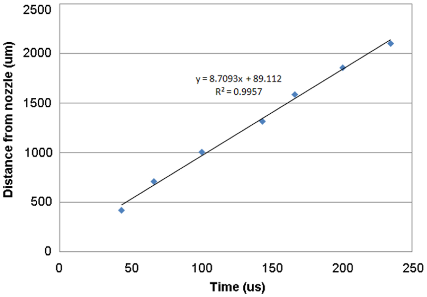
The tail was attached to the droplet head in flight for about 100 µs when a high-jetting voltage was used, as seen in Figure 11(c) to (f). Disintegration of the tail occurred after about 200 µs (Figure 11(g)), when several satellite droplets were formed. Figure 12 shows the distance of the main droplet centre against time for the trial shown in Figure 11. The linear trend line (regression) fitted well to the measurements and its equation represents the droplet head velocity (8.71 m/s). As inferred from Figure 12, the velocity of the main droplet was not affected by the tail disintegration at about 150–200 µs. The tail disintegration behaviour depended on the jetting voltage.
Tracking of the droplet head during the tail evolution (25.0 V, 3 kHz).
Within the first 100 µs after separation from the nozzle, the tail either disintegrated into satellite droplets flying behind the main droplet (with higher jetting voltages) or rejoined the main droplet (with lower jetting voltages). Owing to the differential boundary pressure between the air and the liquid, the surface tension forces of the melt retracted the curvature to reduce the surface energy and therefore the differential pressure, which resulted in the tail evolution. This was described by Lord Rayleigh 16 and is known as Rayleigh instability of a liquid jet.
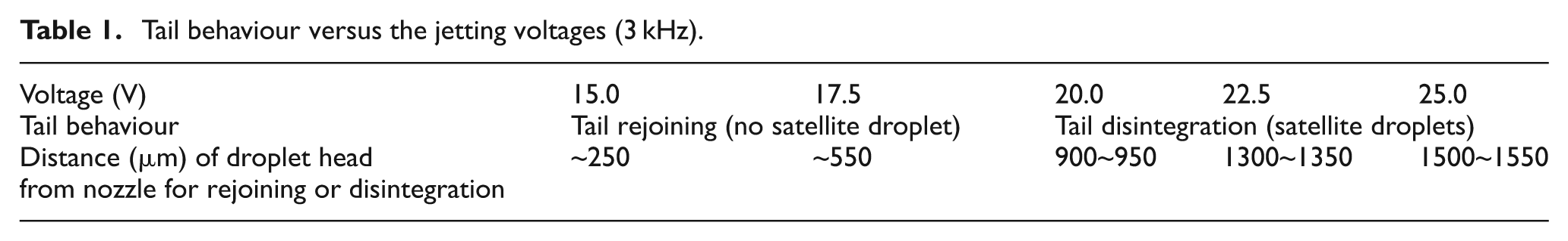
The disintegration/rejoining behaviour and the distance it occurred are shown in Table 1 for different voltages. Droplets generated with 15.0 V had a short tail with no disintegration to form any satellite droplets. The rejoining of the tail to the main droplet for this voltage occurred at about 250 µm from the nozzle. The tail formed with 17.5 V jetting voltage also rejoined the main droplet without disintegration. However, the rejoining distance increased to about 550 µm. In contrast with the jetting voltage higher than 17.5 V, the tail disintegrated into several satellite droplets. The disintegration distance increased from about 900 µm at 20.0 V to 1550 µm at 25.0 V. The tail evolution from formation to rejoining or disintegration occurred within 200 µs of the nozzle actuation for all voltages. The table also suggests the appropriate jetting voltages were 15.0 and 17.5 V to avoid formation of satellite droplets.
Tail behaviour versus the jetting voltages (3 kHz).
Droplet size and kinetics
The size of droplets was considered to be the diameter of the main droplet (after the tail disintegration) or the droplet head (those still having the tail attached) at 1 mm distance from the nozzle. Figure 13 shows the variation of caprolactam droplet size with jetting voltage and frequency. It was almost constant at around 50 µm, which was also the nozzle size. This shows that the droplet size was not affected by the jetting parameters and was owing to the nozzle size. As the droplets produced at 20.0, 22.5 and 25.0 V had satellites, the main droplet was a proportion of the whole material forced out. Therefore, the results for kinetics energy, Weber number and Reynolds number would be based on the main droplet size, which would be deposited onto the surface, independent from the satellite droplet kinetics.
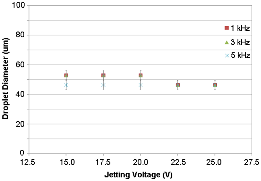
Droplet size versus voltage at different frequencies.
The variation of the droplet kinetics with jetting voltage and frequency was quantified. Figure 14 shows that the range of frequencies used did not have an effect on the droplet velocity. With a higher jetting voltage, a higher amplitude pressure wave was formed and propagated towards the meniscus giving the droplet a higher velocity. The velocity fluctuations and the linear regression of the curve show that the droplet kinetic behaviour was repeatable within the range.
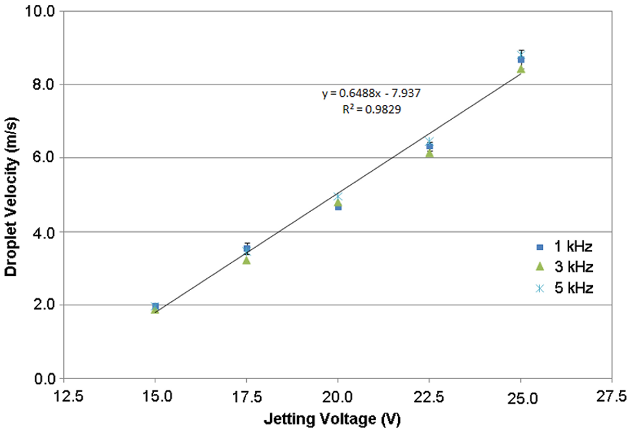
Droplet velocity versus voltage at different frequencies.
A printhead’s ink channel is designed to meet the required droplet characteristics. 8 This is because with each nozzle actuation, a residual pressure wave would exist in the ink channel after the wave hit the meniscus on the nozzle and a droplet is expelled. 9 This would require a delay before the next actuation (affecting the jetting frequency) as the residual pressure waves could make the droplet formation inconsistent. The range of jetting frequencies used in the experiments was not observed to provide a droplet inconsistency or fluctuations in the droplet velocity as shown in Figure 14.
Weber and Reynolds are respectively defined as the ratio of inertial forces to surface tension and viscous forces. The equations are We = ρDVd2/σ and Re = ρDVd/µ, respectively, where Vd is the droplet velocity on impact, D is the droplet diameter, ρ, σ and µ are the molten caprolactam density (1.02 g/cm3 as reported by supplier), surface tension and dynamic viscosity, respectively. Figure 15 shows the result for the Weber number and Figure 16 the Reynolds number. Both the Weber and Reynolds numbers were relatively low for all the settings, which would indicate little tendency of molten caprolactam to splash on the surface during impingement. 13 Therefore, it was expected that, while depositing molten caprolactam, only droplet spreading would occur with no secondary droplets from splashing.
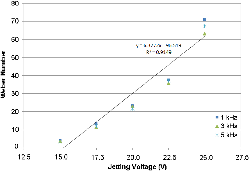
Droplet Weber number versus voltage at different frequencies.
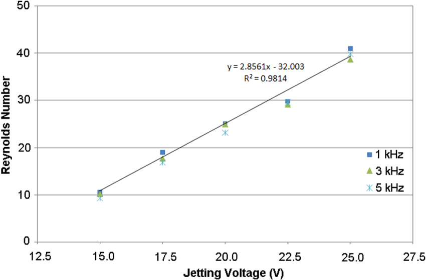
Droplet Reynolds number versus voltage at different frequencies.
Droplet impact behaviour
Splashing was not observed on the heated surfaces. This confirmed the predictions made by the Reynolds and Weber numbers and showed that the jetting parameters were suitable for the deposition trials in further research. Figure 17 shows a smooth spreading of the first few droplets deposited onto the heated surface. The number of droplet being deposited, the total number of accumulated droplets and also the time from the first impingement, are shown in the sequence. No splashing was observed from the impingement of consecutive droplets (onto previously spread melt) for the heated surface.
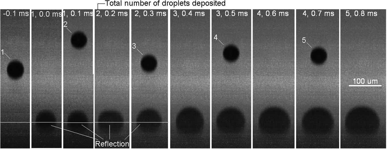
Spreading of caprolactam droplets onto heated static glass surface.
Conclusions
High-speed imaging gave an understanding of the molten caprolactam droplet formation characteristics. Jetting frequency did not affect the droplet formation characteristics that were considerably influenced by the jetting voltage. Oscillation of adjacent nozzles’ meniscus was observed, especially when using higher jetting voltages owing to the cross-talk in the printhead as a result of its shared-wall technology. The meniscus at rest was found to be inside the nozzle. Oscillation of the meniscus during generation of thousands of droplets developed a wetting area.
Jetting voltages above 12.5 V generated droplets and all formed a tail upon separation from the nozzle. With jetting voltages higher than 17.5 V, satellite droplets were formed owing to disintegration of the tail that was as long as 1 mm (25.0 V) at distances beyond 1 mm from the nozzle. Droplet size though was unaffected by voltage and remained mainly constant at about the nozzle size. Droplet velocity was considerably affected by the voltage. When increasing the voltage from 15.0 V to 25.0 V, the velocity increased from 2 m/s to 8 m/s. The Reynolds and Weber numbers though, remained within the range that would introduce a splash-free impact on substrate according to the literature. From the results, a set of jetting parameters was chosen to investigate stable deposition of beads as the next stage of researching the concept of jetting of nylon. The criteria were to have consistent satellite-free droplets and splash-free impact on the surface. The investigation showed that with the chosen jetting parameters, there was spreading upon droplet impact. Consecutive impingement of the droplets onto previously spread droplets also did not cause splashing.
Footnotes
This project was funded by the Engineering and Physical Sciences Research Council (EPSRC) via the Innovative Manufacturing and Construction Research Centre (IMCRC) at Loughborough University.