
Abstract
Wire and arc additive manufacture enables us to build fully dense metallic parts by depositing material in layers using a welding process. Conventionally, in this process, the welding torch is always maintained in a vertical orientation, but this can cause accessibility problems and may require that the part is moved during the deposition process. The aim of the research presented in this article is to investigate the production of geometrical features using wire and arc additive manufacture with positional welding. Positional welding is particularly useful for building features with limited accessibility without having to manipulate the part. In the current work, inclined and horizontal wall features have been built using an inclined torch position. The knowledge obtained from these experiments has been further applied to build enclosed features. Additionally, a range of travel speeds has been investigated to better understand the effect of travel speed on part quality for angled walls. Factors that hinder the quality of the produced features have also been identified.
Introduction
In order to win a greater share in the worldwide market, aerospace and automotive industries face the task of developing products in the most competitive way, in terms of quality, cost and delivery time. Within the aerospace industry in particular, manufacturers are required to produce parts in low volumes with high integrity. 1 The increasing use of materials like titanium 2 and novel designs for integral structures 3 further increase the challenge. When using traditional machining processes, the ratio of material bought to material that eventually goes to the aircraft (buy-to-fly ratio) can be as high as 10:1. This has led the aerospace industry to search for new manufacturing processes that produce less material waste.
A proposed manufacturing solution is wire and arc additive manufacturing (WAAM). It can be defined as the outcome of combining an additive manufacturing process (i.e. arc welding to produce a near-net shape part), and a subtractive manufacturing process (i.e. grinding or machining to produce the final part geometry). The aim of this article is to investigate the production of geometrical features using WAAM with positional welding where the welding torch angle is aligned with the feature to be produced. Such ability will reduce handling of parts and increase the process flexibility. Additionally, key factors for the process performance, such as the welding speed, are investigated. This article presents:
an experimental investigation of the ability of the wire and arc process to fabricate geometrical features useful for mechanical parts in carbon mild steel and aluminium;
the effect of welding parameters on quality of the produced features;
application of the obtained knowledge for the production of enclosed features.
Arc and gas metal arc welding (GMAW) additive layer manufacturing
Two groups of additive manufacturing processes are identified for the fabrication of metallic parts: powder-based and wire-based processes. The former have inherited many features from the rapid prototyping techniques. Hence, one of the common names initially used was rapid manufacturing techniques. 4 Wire- and arc-based additive manufacturing is as old as 1925 5 when it was used to fabricate decorative items. Wire-based processes were initiated as a manufacturing concept in West Germany in the late 1970s using submerged arc welding (SAW) for the fabrication of large scale metallic components. 6
Despite the increasing research interest in the implementation of arc welding processes in large-scale manufacturing, this technology has not been commercially developed. The absence of commercial solutions could be explained by the need for expert welding knowledge along with suitable process control algorithm databases for controlling deposition geometry in order to increase levels of automation. According to the power source that is used to melt the wire, the research effort can be classified as: GMAW,7–10 gas tungsten arc welding (GTAW) with titanium alloys 11 and steel, 12 plasma, 13 and laser 14 additive manufacture.
Regarding GMAW in the 1990s, two significant research developments took place in the UK involving arc processes as a means for part fabrication. One was by Ribeiro et al., 8 in which they described the development of a ‘metal-based rapid prototyping’ process. The second development was carried out by Spencer et al, in which a GMAW process was used as the deposition process 7 with the torch mounted on a six-axis robot. Similar work published by Zhang et al. 15 provides manufacturing guidelines for fabrication of walls and rotational parts.
The use of GMAW is also demonstrated in the development of hybrid processes that use WAAM with machining to produce engineering parts, such as dies for injection moulding parts. 16 A recent example is a process called hybrid layer manufacturing (HLM) that uses pulsed GMAW and focuses on the fabrication of dies. 17 The common feature of these hybrid processes is the use of slicing routines and the vertical to the substrate plate position of the welding torch. The maximum angle achieved of overhang features was 45° 16 without the use of support structures.
The development of novel welding processes, such as cold metal transfer (CMT), can provide improved stability and spatter reduction; features that are important for an additive manufacturing process. CMT is an advanced dip transfer process in which the metal is deposited in the molten pool purely owing to surface tension through the use of reciprocating wire.18–20 The process provides a uniform bead profile resulting in lower surface waviness (SW) and less heat input giving lower distortion and potentially better mechanical properties.18,21
In summary, previous research has demonstrated that welding processes can be used successfully for additive manufacture, but to date there has been limited research into the production of the design features required for real world parts. Song et al. 15 investigated the capability of GMAW to produce design features and reported a limit of 45° for the production of unsupported inclined walls using a vertical torch.
Experimental – walls
Background to experimental work
A detailed study has been undertaken at Cranfield University to investigate the production of vertical walls using WAAM with the torch in PA/1G welding position (according to PD CEN/TR14633:2003). The quality of the walls produced was evaluated in terms of: (i) effective wall thickness (EWT), which is defined in this context as the maximum constant wall thickness achieved after machining the as-deposited walls to net shape; and (ii) SW, defined as the average maximum peak-to-valley distances measured from a profile of a given area in the wall (see Figure 1).
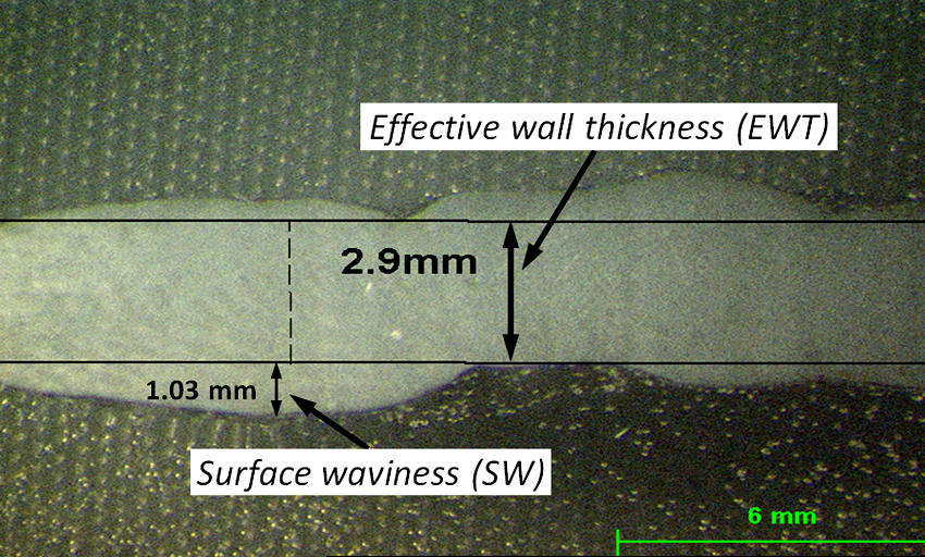
Definition of EWT and waviness.
Results empirically derived from this study using mild steel are shown in Figure 2(a). These data show the relationship between travel speed (TS), wire feed speed (WFS) and EWT. Results can be used for predicting the EWT achievable for any given set of process parameters. The influence of wire diameter and TS on SW was also investigated. The graph in Figure 2(b) indicates that wire diameter has a positive but moderate influence on SW, irrespective of the TS.
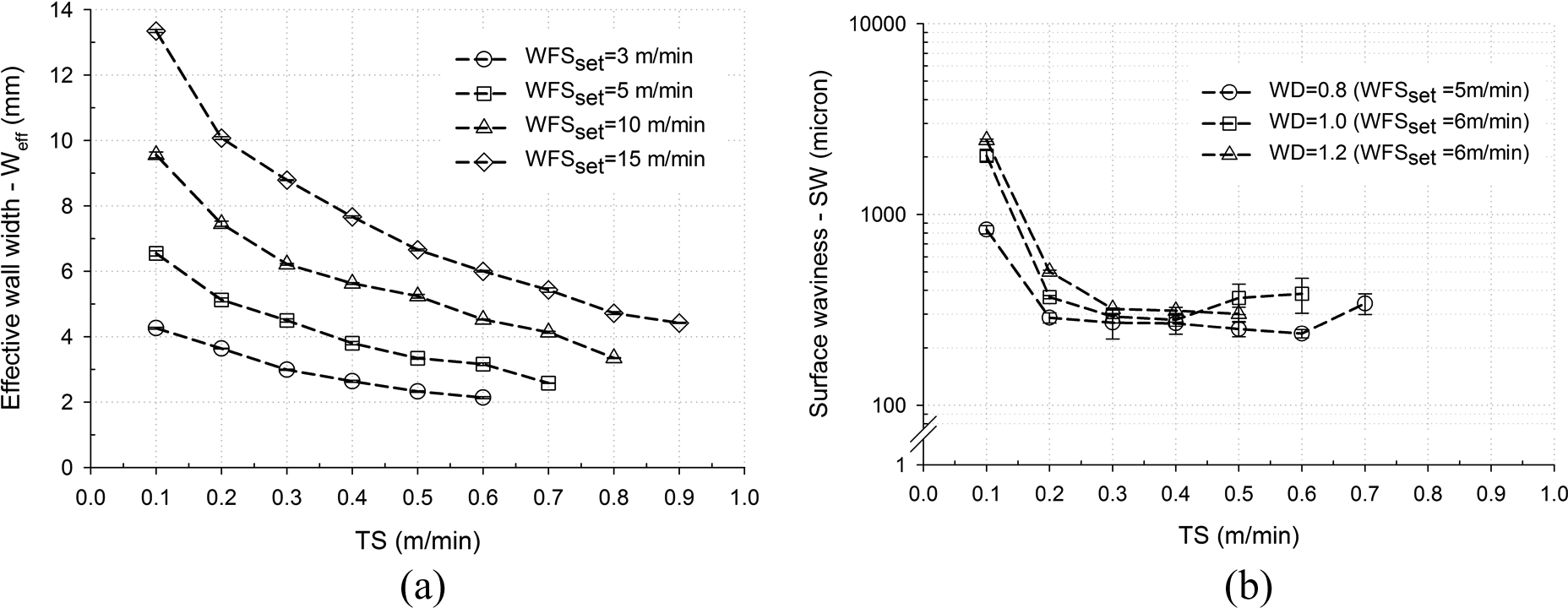
(a) Effect of TS on EWT (b) Influence of the wire diameter on SW
The results of this first study focused on the production of vertical walls using WAAM. The aim of the remainder of this article is to investigate how features that would be required for real world parts can be produced using this process. Positional welding in WAAM will be applied to achieve greater flexibility and accessibility with reduce part manipulation during the deposition process. The production of inclined and horizontal walls and closed shapes using out of position welding will be investigated.
Materials and consumables
For experiments with carbon steel substrate, material grade S355 with size 350 mm × 300 mm × 15 mm were used. Consumables used were: a shielding gas mixture containing 80% argon and 20% CO2; welding wire ER70S-6 grade with 0.8 mm diameter. Equipment utilised for the experiments were: Fronius CMT, Transpulse Synergic 5000 welding machine and the ABB type MTB 250 6 axis robot.
The same equipment and set up has been used for aluminium experiments. Material and consumables were chosen based on their successful implementation in previous experiments, while process parameters were adjusted by trial and error. Substrates of 6082 grade with a size of 12 mm × 200 mm × 250 mm were used. The shielding gas mixture was argon (99.998%) and a mixture of 75% He and 25% Ar. The welding wire used was ER4043 with 1.2 mm diameter.
Steel inclined wall fabrication
In order to fabricate the inclined walls the technique shown in Figure 3 has been employed. The angle of the torch is set to be equal to the targeted wall angle. The torch is offset after every bead in the direction of the wall growth. Furthermore, the torch welding travel direction is reversed after each layer deposited.
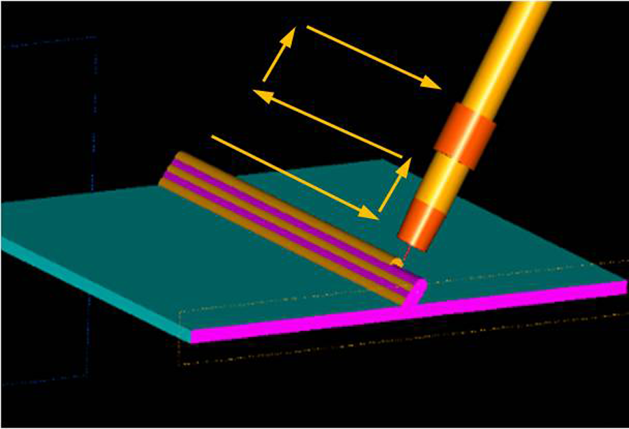
Inclined wall fabrication.
The welding parameters utilised for the inclined wall fabrication with 4 mm in thickness were derived from the empirical data provided from Figure 2(a) and are shown as follows.
WFS= 6 m/min.
WFS/TS = 15.
Torch height increment = 1.75 mm (collinear to the wall)
Contact tip to work distance (CTWD) is 11 mm
It should be noted herein that experiments were conducted at constant deposited cross-sectional areas; that is, constant ratio of deposition to weld TS (WFS/TS). This approach was adopted to ensure the good quality and uniformity of the welds deposited and, therefore, avoid erratic combinations of welding parameters; for example, use of high TS with low WFS rate. The increment of 1.75 mm was decided upon after empirical trials indicated the bead height. Four inclined walls were produced with angles to the substrate plate of 60°, 45°, 30° and 15°. The walls are 200 mm long, with wall height of 60 mm and wall thicknesses that vary between 4 mm and 5 mm. Sections of these walls are shown in Figure 4. Angle measurements were conducted with a conventional inclinometer and the accuracy achieved was ±0.5°. In this article the length is the wall dimension parallel to the torch direction and height is the dimension of the wall growth.
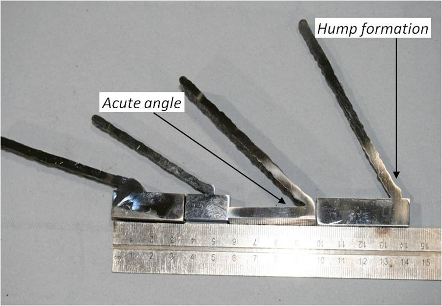
Sections of inclined walls.
The choice of the appropriate welding conditions is important, especially in the formation of the angle during the laying of two or three first beads of the wall. It appears there is a hump formation in the second or third bead very close to the wall base. Furthermore the acute angle acts as a stress raiser, which could worsen with smaller angles.
To overcome this problem the strategy described in Figure 5 has been utilised. According to this approach the first layer consists of 3 beads, positioned similar to a cladding application, the second layer of 2 beads and the third layer of one bead. All three layers that form the wall base have been positioned in the form of a pyramid. The torch angle is vertical to the substrate plate for the fabrication of the wall base. The wall beads to form the wall itself are deposited aligned with the wall angle (i.e. at a 15° angle with the horizontal plane).
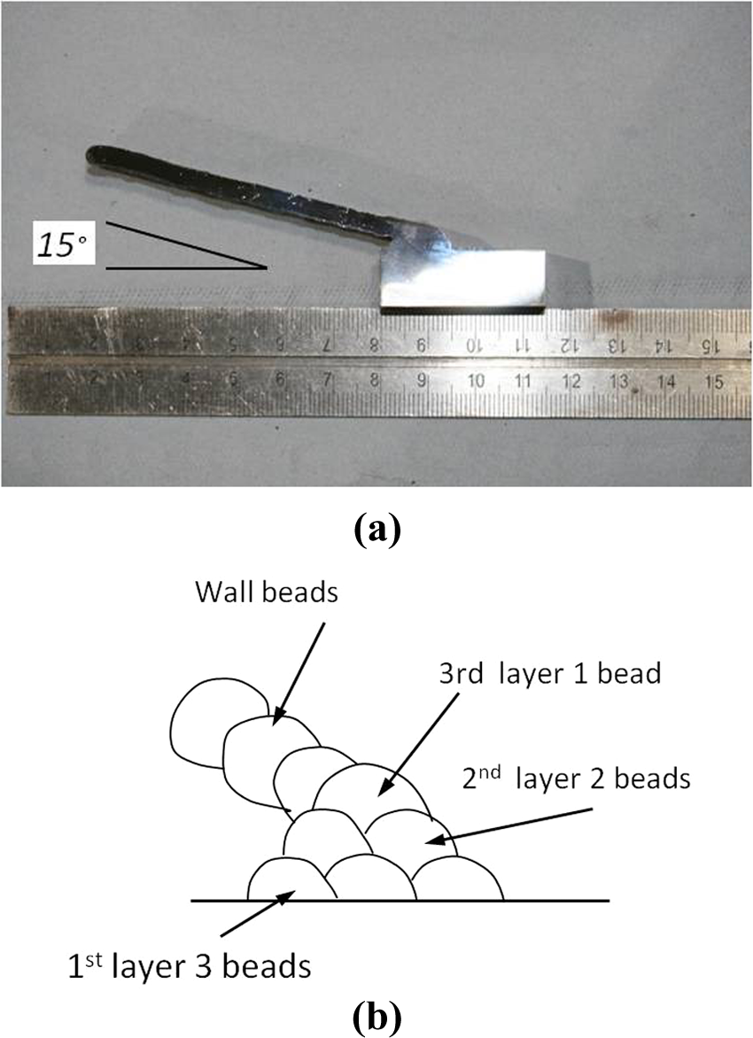
Low angles solution.
Using this technique we were able to:
eliminate the hump;
create a small radius in the place of the acute angle;
gain accessibility for repair or machining (depending on the angle and the ‘pyramid’ height).
Disadvantages of this method could include the demand for more complicated programming and the possibility of weld defects in the cladding operation. The outcome of these experiments showed that additive manufacturing with CMT can operate in positional welding conditions in a range of angles from 90° to 15°.
Horizontal walls
Based on the successful production of walls with small angles, building a 0° overhang as an extension of a 6 mm plate was investigated. Welding parameters for the CMT process were WFS = 6 m/min and WFS/TS = 15 (see Figure 2(a)). The technique used of alternating the weld torch travel direction for each layer was the same as for the inclined wall. For the first attempt the torch was collinear with the plate, as shown in Figure 6(a); for the second attempt the torch was set with a 30° offset from the horizontal plane as shown in Figure 6(b).
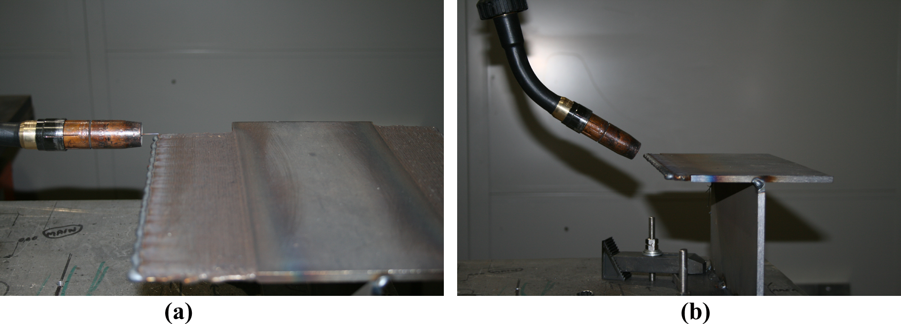
Building of overhang wall 0°; (a) torch collinear, (b) torch at 30° offset.
The horizontal torch trial produced a plate extension of 4 mm thickness approximately 100 mm long (Figure 7(a)). Similarly the 30° offset torch trial produced an extension of 4 mm thickness approximately 80 mm long (Figure 7(b)). Checking with a conventional inclinometer we can find that there is a 0.1–0.3° diversion of horizontal plane of the plate. In order to produce a wall with thickness greater than 6 mm the welding parameters used with CMT welding process were WFS/TS = 45 and WFS = 9 m/min. Again, these parameters were selected from the empirical data provided from Figure 2(a). The outcome is shown in Figure 7(c). It is a horizontal wall with wall thickness approximately 7 mm, and length 80 mm. Success was achieved by increasing the WFS, thus increasing the current while keeping the TS low (0.2 m/min). This resulted in an increase in the heat input per layer deposited.
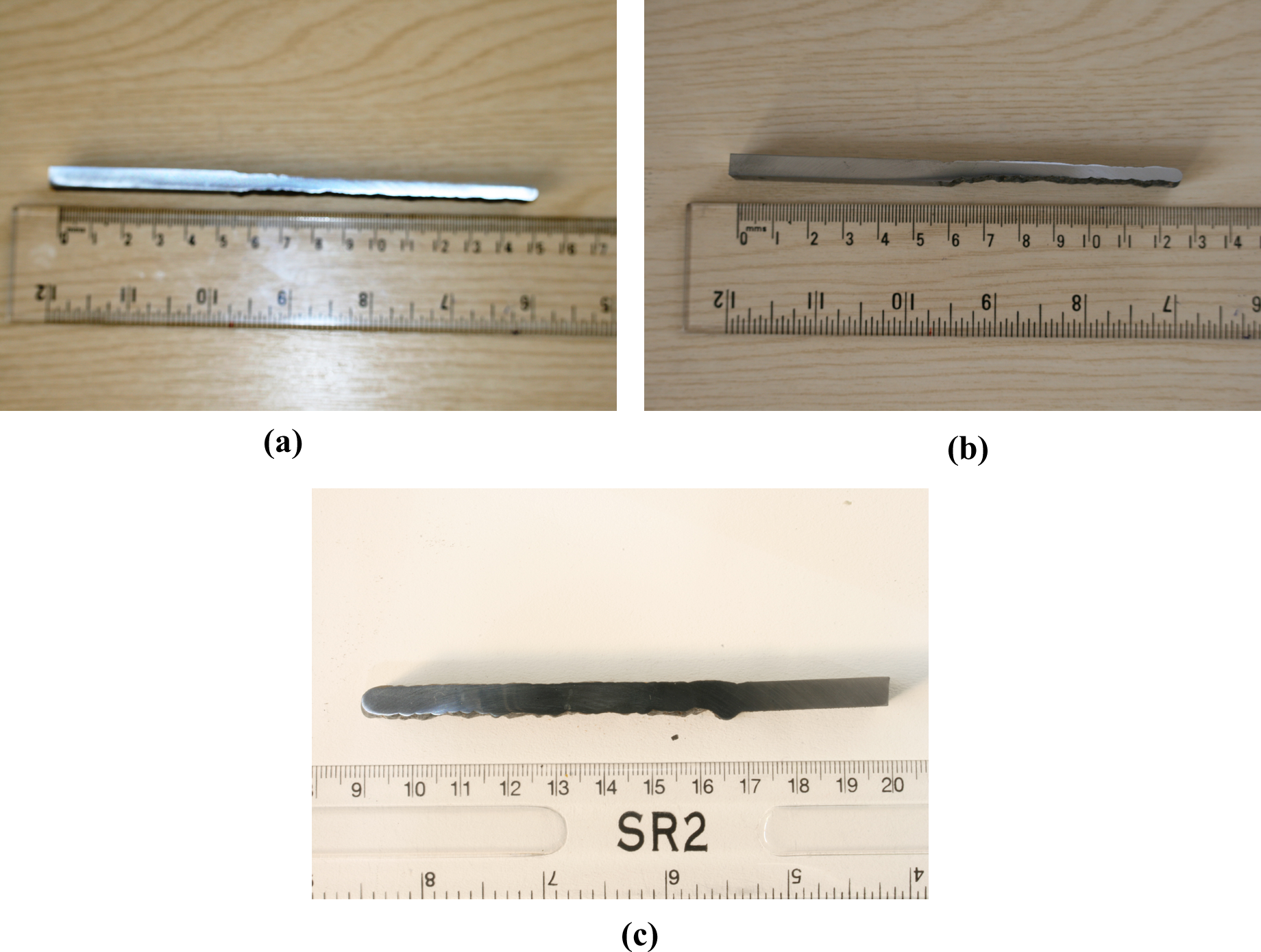
Overhang wall; (a) torch collinear, (b) torch 30° offset, (c) 7 mm wall.
Effect of the wall angle on steel and aluminium walls
The successful application of the process in fabricating inclined steel walls was followed by experiments for the fabrication of aluminium walls. A more detailed study was then undertaken for steel and aluminium to investigate the effect of the wall angle on the wall by building three walls of 0°, 30° and 90°.
The experimental set up and wall building strategy applied were the same as previously described. Welding parameters used for steel experiments were WFS equal to 7 m/min and TS equal to 0.5 m/min with target EWT 4 mm. A shielding gas mixture containing 80% Ar and 20% CO2 was used with a flow rate of 15l/min. For aluminium experiments the WFS and TS were 3.7 m/min and 0.5 m/min, respectively. The gas mixture was argon (99.998%) with a flow rate of 16l/min. The CTWD was maintained at 12 mm throughout the experiments. A second experimental set was also conducted for aluminium with the same parameters, the only variation being the shielding gas with a composition of 75% He and 25% Ar. In order to investigate the effect of inclination on the wall quality, three walls were built (0°, 30° and 90°) for both steel and aluminium. While the target for the argon shielded deposition is 4 mm (based on previous experiments), there are no previous experimental data for the use of a helium mixture.
After welding, the samples were cut perpendicular to the substrate plate and polished sequentially with typical grit sizes ranging from 240 to 4000 (ANSI (American National Standards Institute) grit). The samples were observed under the optical microscope with 0.5× magnification lens. The criterion for the process performance was the EWT (see Figure 1). The EWT is measured using Acquis software integrated with the microscope as the distance between two parallel lines constructed by the measuring software. The lines are constructed in such a way that forms the maximum parallel section that can fit within the section. The SW is measured as the maximum peak size measured from the effective wall surface. The results are shown in Figure 8.
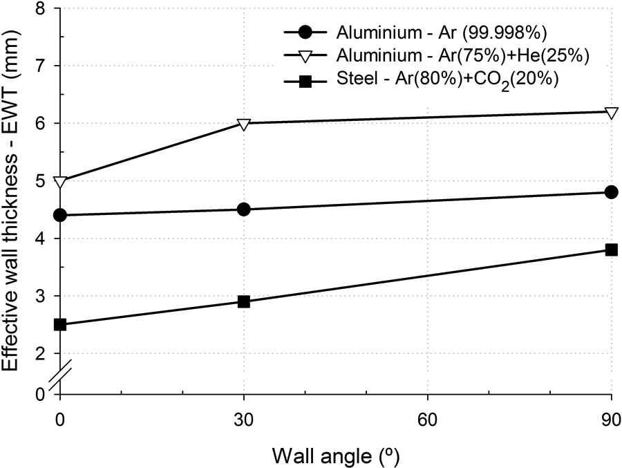
Effect of wall inclination on the EWT.
For the steel walls it can be seen that the EWT increases as the wall angle increases. There is a drop of 1.3 mm in the EWT from vertical to horizontal position in a linear manner. Similarly the aluminium walls with 100% Ar shielding gas show a linear decrease, but it is significantly lower (i.e. 0.4 mm), than the steel walls. The walls built with a helium and argon mixture as shielding gas exhibit a 1.2 mm decrease in the EWT from vertical to horizontal position. There is, however, a difference with the two previous cases. The EWT decreases only 0.2 mm from the vertical wall to 30° inclined wall compared with a further 1 mm decrease from 30° wall to the horizontal wall.
Effect of the torch TS
The experiments for inclined and horizontal walls indicated that TS is a major factor for wall quality. In order to study this effect on horizontal walls, a set of experiments were conducted in which the TS was varied from 0.078 m/min to 0.6 m/min while the WFS/TS ratio was kept constant. This ensured that the amount of the deposited material per unit length remained constant. Additionally, as the average current and the power input vary linearly with the WFS, keeping the ratio constant ensures that the heat input is constant. The experimental matrix is shown in Table 1. The envelope of welding parameters was dictated by the limits of the machine’s software.
Experimental matrix.
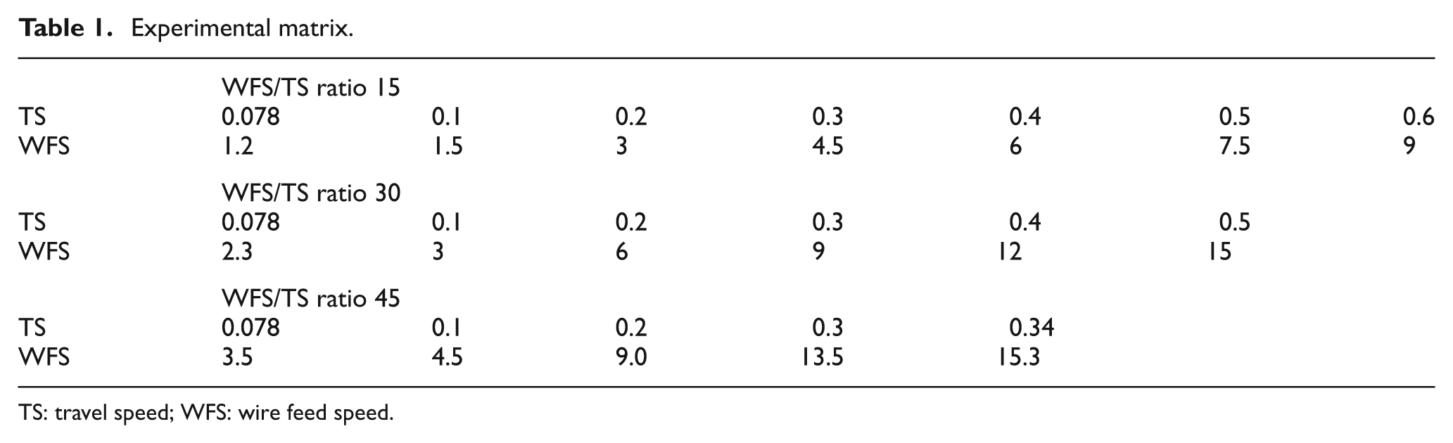
TS: travel speed; WFS: wire feed speed.
The same procedure was also followed for the samples preparation. The criterion for the wall quality was the SW measured by the software Axiovision.
The results of the waviness measurements for these experimental series are presented in Figure 9. The common feature of the graphs is a U shape, which is more evident in the bottom SW and the 15 ratio both top and bottom sides. Within the investigated parameters the speed level that corresponds to the lowest waviness is between 0.2 and 0.25 m/min. Further increase of TS leads to a deterioration of the wall quality as shown in Figure 10. The walls shown were built with a ratio of 30 and the TS starts from 0.2 m/min until 0.5 m/min increased by 0.1 m/min.
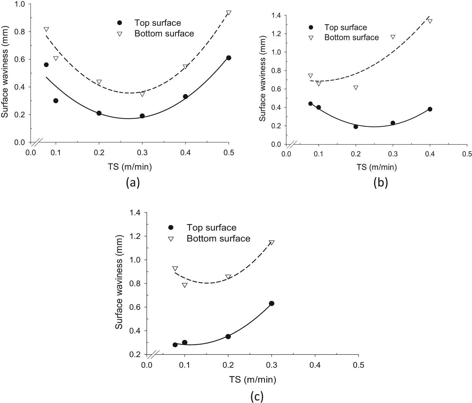
SW versus travel TS for WFS, TS ratio (a) 15°, (b) 30° and (c) 45°.
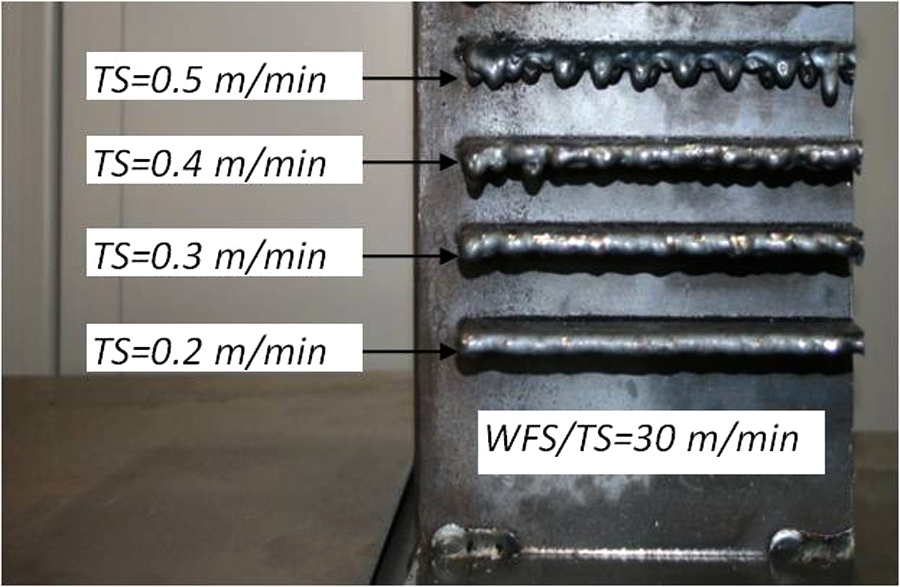
The deterioration of wall quality by increasing TS.
Experimental – enclosed shapes
Closed shapes
The knowledge obtained from the previous experiments was used to fabricate closed section shapes. The two vertical walls were built first and then bridged by the overhang wall.
The first closed section required a gap of 50 mm to be bridged (Figure 11 (a)). The torch position is maintained in a vertical position during the fabrication of the vertical walls. The torch was inclined at 45° for the horizontal overhang wall fabrication for accessibility reasons. Welding parameters and processes used are the same as those for the horizontal and inclined walls, respectively, and thickness achieved was 4 mm. The horizontal part started from one wall and continued across the full 50 mm gap. At the start of the horizontal wall a smooth radius was created achieving fusion between the two walls. However, at the end a sharp corner was created and the walls were not fused in their entire thickness.
Subsequently a second box section was fabricated with the two vertical walls at a distance of 200 mm. The horizontal wall of the box was produced in two parts by starting it from both ends and joining in the middle. For accessibility reasons the first part of the horizontal wall was built with torch angle at 30° and for the second part (starting from the opposite direction) the angle was increased to 50°. This practice, although improving the connection with the vertical wall, caused misalignment of around 1 mm between the two parts. Subsequently the quality of the joint was not the optimum and fusion was not achieved through the whole thickness of the overhang wall (Figure 11(b)). However, the misalignment can be avoided by keeping the torch angle the same for the two parts and using a higher heat input process to achieve fusion.
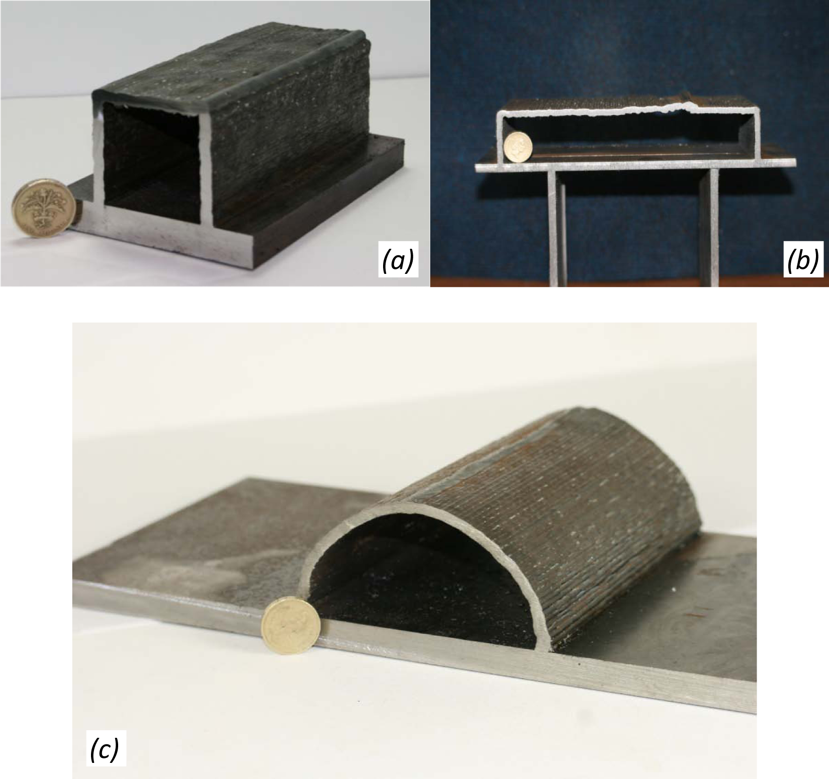
Closed sections; (a) 50 mm square section, (b) 200 mm overhang, (c) 50 mm radius semicircle.
Curved shapes
The process has hitherto demonstrated its capacity to produce walls in directions from 0° to 90°. A challenge for the process would be to achieve the production of curved three-dimensional (3D) walls or even closed shapes that comprise of curved walls. The objective of the experiment was to fabricate a closed half circle.
The strategy for accomplishing the task was to build two quarter circles and join them in the middle. In order to build a quarter circle the robot was programmed so that the x (from centre to circle line) and z (normal to substrate plane) coordinates satisfy the circle formula

The x value was used as input and the robot program produced the z coordinate. The starting x value is equal to the radius and is reduced by one until it becomes 0 and the z value is equal to radius. Higher density points were used to ensure smooth profile of between x = 50 and x = 49 mm, where the semicircle joined the substrate. Welding parameters were TS = 0.2 m/min and WFS/TS = 15. The torch was constantly inclined at 45°.
In order to avoid the problems that emerged in the join of the box section horizontal walls, a standard GMAW process was selected in order to provide higher heat input and achieve fusion for the entire thickness of the wall. A 60°‘V’ preparation joint was created and filled with the filler wire used for the wall fabrication. The successful creation of the half section feature is shown in Figure 11(c).
Discussion
Inclined walls and closed shapes
The initial welding parameters were derived by experiments on vertical walls, as shown in Figure 2. Based on these results, parameters were selected to produce inclined walls with thicknesses within a range of 4 mm to 5 mm, and these were utilised successfully to fabricate walls at all angles between 0° and 90°. One important feature of the fabrication is that the layers represent actual weld bead layers determined by the welding parameters and provide great flexibility on CTWD and the torch offset when the torch is collinear with the direction of fabrication. This means that complex wall shapes can be fabricated using a flexible slicing approach rather than a rigid parallel slicing routine as used in a conventional rapid prototyping process or the wire-based research work previously described. The layer height is defined only by the wall bead height as produced and the torch offset in whichever direction the wall is formed.
Wall type features could be added in any orientation from 0° to 180° without the use of support structures or the need to rotate the part. This makes the process more flexible in incorporating features on a part produced by other process or features that are not included in an original design. Additionally, it can be used for repair works.
Hollow sections can be added onto parts and replace areas where the volumes are not required but are nevertheless unavoidable and necessitate removal by machining. Figure 11(c) demonstrates that curved 3D sections can also be built, providing not only a desirable geometric feature in real world parts, but a more favourable structural solution to enclosed structures made from rectilinear walls that include corners. EWT can be controlled with the welding parameters for all positions including the horizontal walls.
Effect of wall angle on steel and aluminium walls
The primary observation on the effect of the wall angle on the steel walls is that the EWT is reduced with angle reduction; a result of gravity forcing the molten metal to move to the lower side of the wall when inclined. Additionally, Figure 8 shows that the effect of angle is more evident in steel walls owing to the density of carbon steel (7860 kg/m3) being higher than aluminium (2690 kg/m3). Hence, the effect of gravity force is greater on carbon steel compared with aluminium making it decrease the EWT more significantly.
From graphs shown in Figure 8 we can also conclude that by using 99.998% Ar as shielding gas, the decrease in EWT with change in angle of inclination is less significant compared with a shielding gas mixture of 75% He and 25% Ar. It is also observed that the EWT is greater when helium is used compared with an argon mixture. This is because of the presence of helium, which has higher ionisation potential than argon and, therefore, higher arc power. As a result, there is higher heat input, which gives higher fluidity to the weld pool. This makes the bead wider, hence the greater EWT when using a shielding gas mixture of 75% He and 25% Ar. The higher fluidity and the effect of gravity however, rapidly reduce the EWT when building the horizontal wall.
Effect of the torch TS
Figure 9 shows the SW against the TS for the three different ratios. These graphs highlight TS range that give minimum waviness. The deterioration of the wall quality at high TSs can be attributed to the humping welding defect in correlation with the gravity that is present in a horizontal wall. The gravity effect is more evident in the bottom surfaces where the SW is always higher. For lower TSs, increased waviness is observed in ratios 15 and 30 and is reduced as we move towards the optimum speed. In ratio 45 the quality simply deteriorates with the TS increase. This leads to the conclusion that for lower ratios, lower TS equates to low current levels. This reduces the pool fluidity, and therefore, the fusion area between layers, hence there is greater distance between peaks and valleys.
The effect of TS is shown in Figure 10 where walls are built with speeds higher than the speed of 0.2 m/min. The shape of walls indicates the humping welding defect, which is a high-speed defect that occurs owing to backflow momentum of the molten pool. The shape of the welding bead is similar to a beaded cylinder morphology type of humping with intermittent spheres deformed owing to gravity. 22
Conclusions – further work
Conclusions drawn from the experiments are listed below.
Walls with various angles ranging from vertical to horizontal positions can be deposited with CMT using empirical process control models. The torch can be inclined to the wall direction in order to produce angled walls.
With wire and arc additive manufacture the fabrication of closed shapes is possible and could be used as hollow features when weight reduction is required in structures.
Aluminium as well as steel walls have been fabricated using the CMT process. Gas mixture affects the EWT.
For the investigated range of WFS/TS ratio a TS of 0.2 m/min provides the best quality results in terms of SW and alloy efficiency.
Wall angle directly affects the EWT and needs to be included as a factor in empirical models.
The findings of the current research could be used as the basis of a manufacturing or design guide. Other GMAW variant processes, as well as filler material sizes, should be investigated regarding their capacity to produce the same features. The research can also be extended to other materials that have, or will have, an extended use in the future, such as titanium alloys.
Footnotes
This project has been funded by the IMRC/EPSRC project 131 at Cranfield University.