
Abstract
Hollow needles are commonly used in many areas of medicine, yet there has been limited research on needle tip geometry. A better understanding of needle tip geometry can lead to the creation of an optimized needle tip geometry design which would greatly benefit the procedure of biopsy, where a needle is used to cut and remove tissue from the body. The present research develops mathematical models to calculate the inclination and rake angle along the cutting edges of needle tips generated by curved surfaces. The parameters of needle insertion length and inner needle tip surface area are also examined. Needle insertion force is predicted based on needle geometry and calculated for curved and flat plane tip needles. A concave needle produced lower cutting forces than the convex and bias bevel needles. It is found that utilizing curved surface needle tip geometry, as opposed to flat plane geometry, allows for greater control in varying rake and inclination angles on the needle. This greater flexibility allows for more control in designing an optimized needle tip.
Introduction
Hollow needles are commonly used throughout many areas of medicine. Needles are utilized in a wide variety of procedures including biopsies, regional anesthesia, blood sampling, neurosurgery, drug delivery, and the radiation cancer treatment brachytherapy. 1 Needle biopsy is a medical procedure where the sharp edge of a hollow needle tip is inserted into the body to cut and extract tissue for diagnosis. The cutting efficiency of the needle dictates the volume of tissue that can be extracted from a thin needle. An end-cut style needle for biopsy has a very high failure rate at capturing tissue. Ubhayaker et al. 2 reported a 27% failure rate of successful tissue capture in end-cut biopsy experiments. Longer biopsy tissue samples allow for significantly better cancer detection in the case of prostate cancer. 3
In biopsy, needle tip geometry plays a significant role in needle cutting efficiency. 4 The geometry of the needle tip can be characterized by the same critical parameters examined in oblique cutting including the inclination angle λ and rake angle α.5,6 Other geometrical factors that may influence biopsy performance include the needle tip insertion length L and inside needle tip area A. Hollow needle experimental results have shown that inclination angle affects the needle insertion force and that needles with too low a value of λ fail to successfully cut the tissue.4,7 Understanding the needle tip parameters λ, α, L, and A is important for selecting needle tip geometry for efficient tissue cutting in biopsy.
The inclination and rake angle of needles generated by flat planes have been studied. 8 Effects of needle geometry on insertion forces and needle deviation were analyzed by O’Leary et al. 9 and Podder et al. 10 for solid plane needles. Bending analysis of basic bevel plane needles has been performed in many studies.11–13 All of these studies focus on traditional needles formed by planes, not curved surfaces, and neglect to explore L and A. The goal of the present research is to develop mathematical models to calculate α and λ for needle tips formed by curved surfaces and also to study L and A for flat plane needles.
Traditionally, needle tips are generated by a special burr-free grinding process where flat planes are cut into the needle, as shown in Figure 1(a). Advanced grinding techniques could allow for needles of curved surface geometry, as shown in Figure 1(b), to be manufactured. Needle tip profiles with smaller internal radius of curvature would require smaller grinding wheels, which would increase the manufacturing complexity and cost. The flat multi-plane symmetric needle tip is commonly used in end-cut biopsy. This needle tip is cut by planes (P = the number of planes used) that are tilted by an equal angle ξ relative to the needle axis and placed in equal intervals around the circumference of the cylindrical needle (see Figure 2). Currently no curved surface needles exist on the market and the potential benefits to biopsy and other medical procedures are unknown. The present research explores the curved needles for manufacturing and future experimental evaluation.
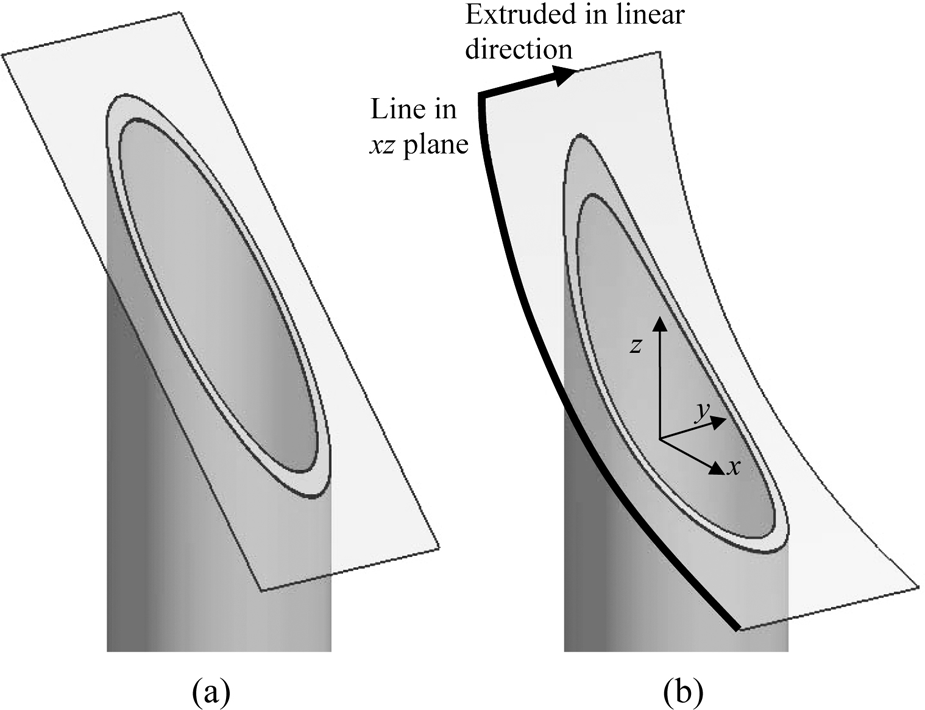
Needle tip formed by (a) flat plane and (b) curved surface.
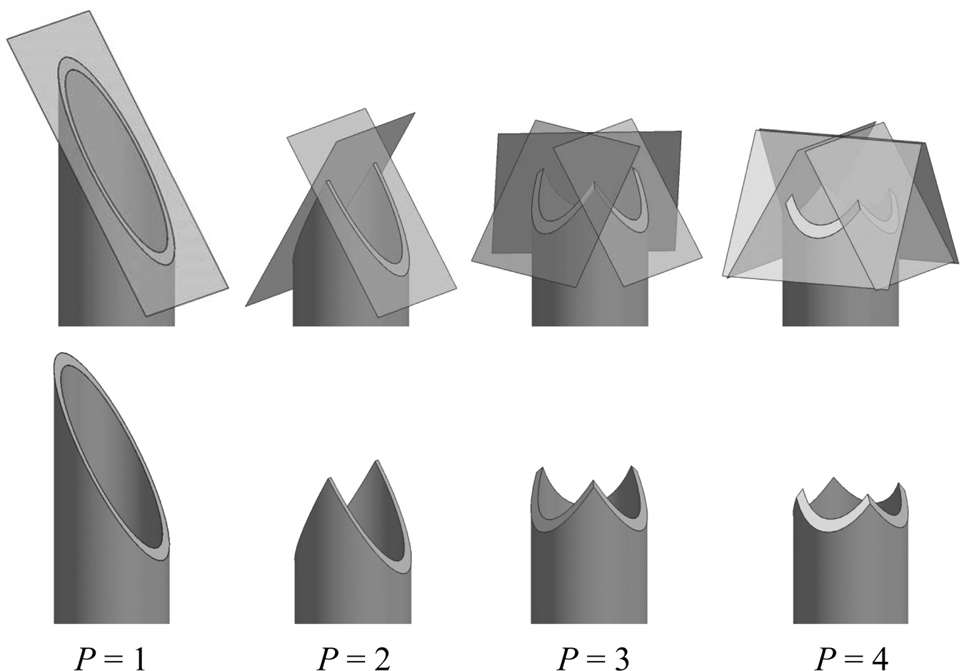
One-plane and multi-plane symmetric needles.
One simple and basic type of curved surface needle could be formed by one or more surfaces constructed from a two-dimensional (2D) line being extruded in a linear direction, as shown in Figure 1(b). This style of curved surface needle would be relatively simple to grind because the slope of the surface cut into the needle is constant in a linear direction across the needle, meaning a grinding profile could be cut straight across the entire needle. Other types of curved surface needles could be formed by having a curved surface with a varying slope along any direction, which would be more difficult to manufacture.
The parameters L and A are important to biopsy performance. The needle tip insertion length and the inside surface area of the needle tip are parameters that tell, respectively, the distance of needle insertion necessary to begin capturing tissue and the rate at which frictional resistance on the tissue will increase when it is being cut. Optimizing these parameters along with λ and α can lead to optimized biopsy performance.
In the present research mathematical models are developed that describe the inclination and rake angles of curved surface needle tips. The inside needle tip area and length of insertion are then discussed. Finally a needle force model is developed which examines the role needle geometry plays in needle forces.
Inclination angle of curved needle
The inclination angle for any style of continuously differentiable, first order derivative of cutting edge is continuous (class C 1 ), curved needle tip can be found once the needle tip geometry of the cutting edge is defined. An example of this style of needle is shown in Figure 3. A xyz axis is defined with the z axis coinciding with the needle axis and the x axis passing through the lowest point in the z direction of the needle tip profile. The outside radius of the needle is ro, the inside radius is ri, and γ is the radial position of a point on the needle cutting edge.
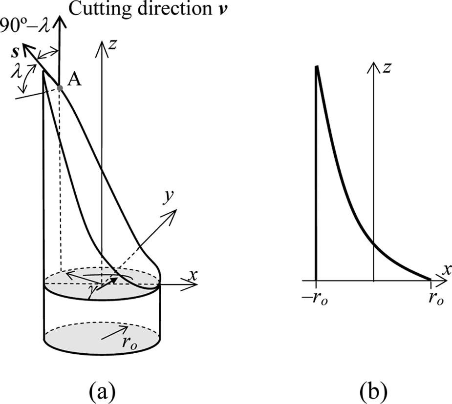
Curved surface needle: (a) outside curved profile and (b) xz cross section.
Parametric equations (1) and (2) respectively describe both the inside and outside needle edge
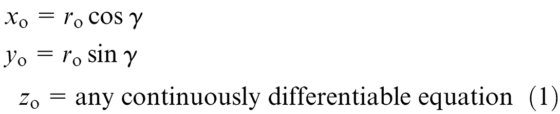
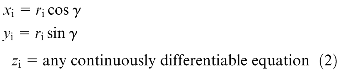
For constructing a needle using traditional grinding techniques, a surface would be cut into a needle that mathematically could be described as a 2D line being extruded in a linear direction. This constant slope along the needle edge causes the inside and outside cutting edges to be identical except for the radius that describes its position,
The normal vector of the xy plane is

This leads to the equations for the inclination angle of any differentially curved needle
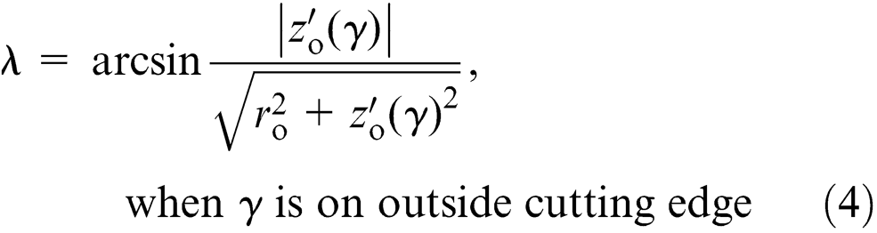
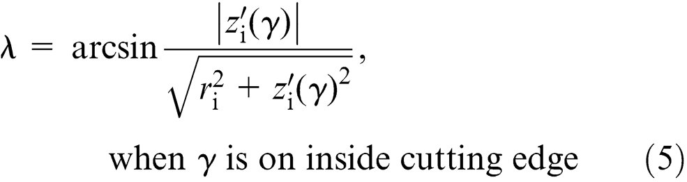
Needles formed by 2D lines being extruded in a linear direction contain the same slope along the inside cutting edge as the outside cutting edge, meaning the radius dependence will drop out of the inclination angle equations and equation (4) will equal equation (5) around the entire needle (0 ≤ γ ≤ 360°). If the needle tip is formed in another way then special attention must be taken to determine where there is an inside cutting edge and an outside cutting edge. On one-plane bias bevel needles for instance, for −90° < γ < 90°, the inside needle edge acts as the cutting edge and, for 90° < γ < 270°, the outside needle edge acts as the cutting edge, as marked in Figure 4.
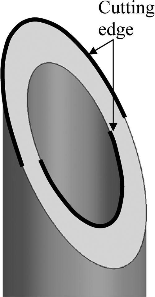
Cutting edge on the outside and the inside of a flat plane needle.
Rake angle of curved needle
As illustrated in Figure 5, the rake angle of a needle is defined as the angle between planes
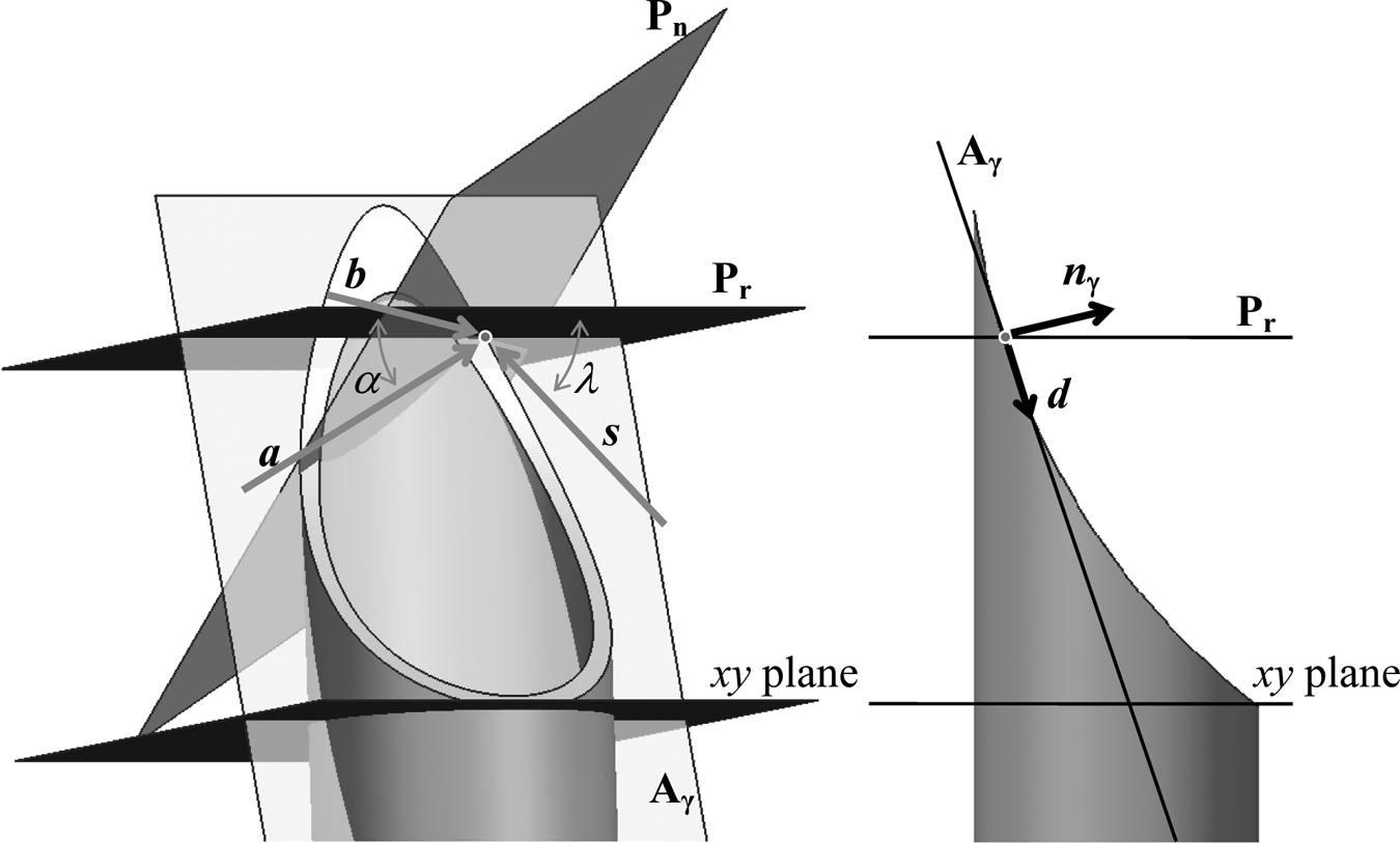
Rake angle of a curved surface needle.
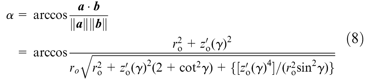
If the needle surface is formed by a 2D line drawn in the xz plane being extruded in the y direction (a configuration that could be easily ground into a needle), vector
Vectors
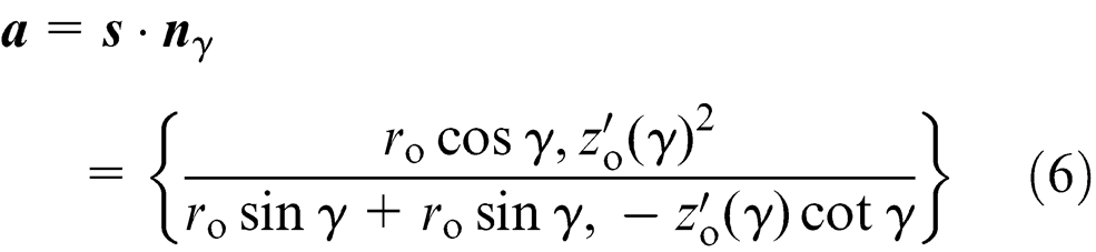

The rake angle is the angle between vectors
Cutting length and inside needle tip area
The cutting length of the needle L and the inside needle tip area A have yet to be explored in needle research. The cutting length is defined as the length of the needle tip in the z direction, as shown in Figure 6. This is an important parameter because the tissue must travel over this length before it can be cut and captured inside the biopsy needle. Ideally the cutting length should be as small as possible to minimize the needle insertion depth needed to capture the tissue.
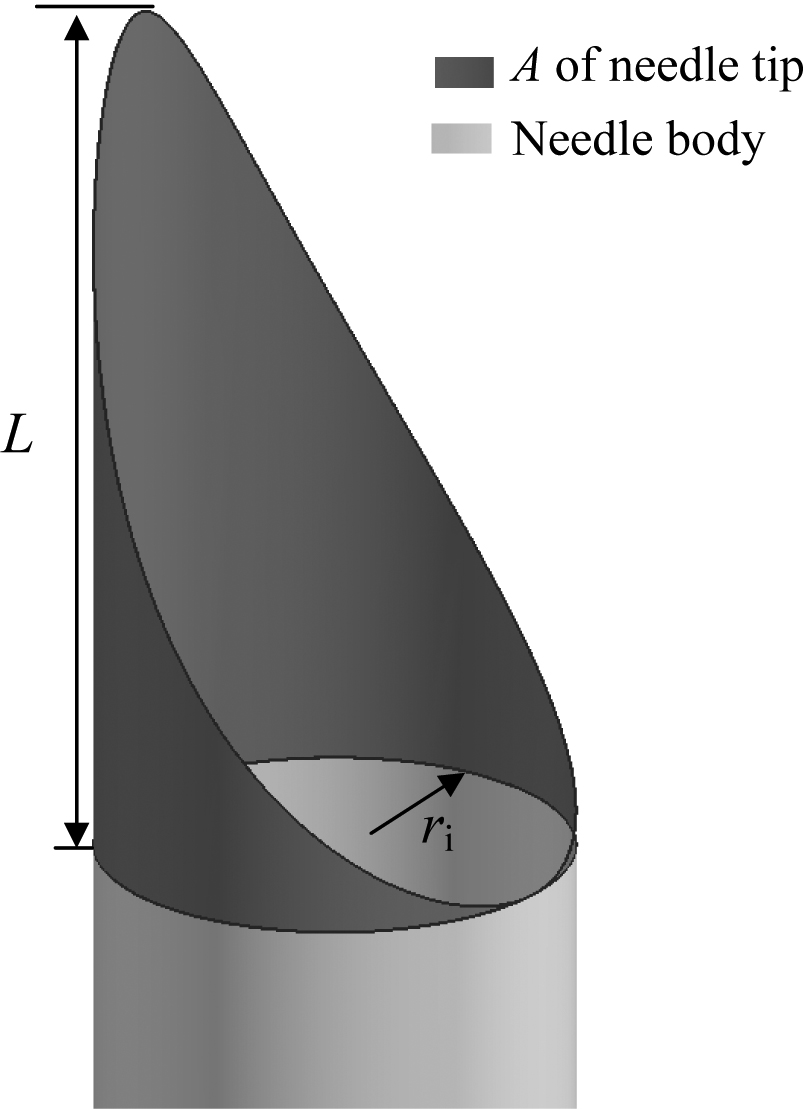
Insertion length L and inside area A of a needle tip.
The increase in inside needle tip area upon insertion is an important parameter because it determines the amount of friction the biopsy segment will encounter as it first begins to slide into the needle, as shown in Figure 6. If this initial friction force is too great, the biopsy segment may not flow into the needle, causing the biopsy to not capture any tissue.
A MATLAB program was created to solve the values of A along insertion and L on symmetric multi-plane needle tips. The necessary inputs were the number of planes, the bevel angle, and the inside needle radius.
Results
Inclination angle
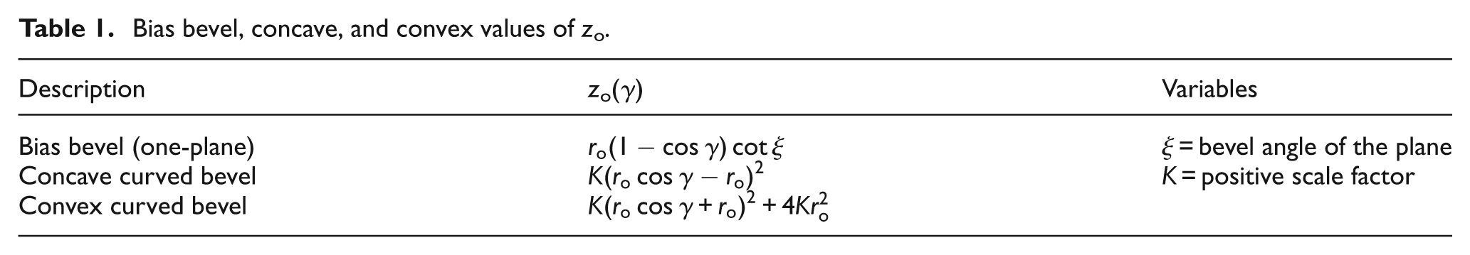
The inclination angle of convex and concave curved surface needles are examined and compared to the traditional flat plane bias bevel needle. The inclination angles for a bias bevel, concave, and convex needle are found using equations (4) and (5) along with the zo values in Table 1.
Bias bevel, concave, and convex values of zo.
The needle tip profiles created using the zo values in Table 1 are shown in Figure 7. Concave and convex needles are formed by curved surfaces cutting through the needle tip profile with a given scaling factor K. When K = 1 the insertion length is 4 while when K = 0.5 the insertion length is 2. Therefore, a lower K value scales down the needle tip insertion length.
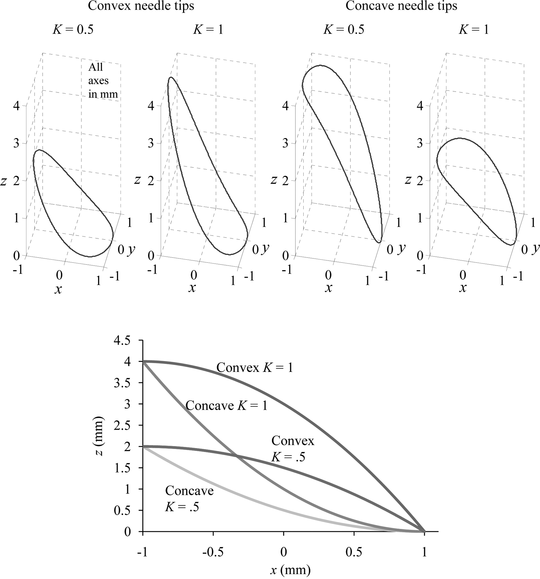
Concave and convex needles given ro = 1 mm, K = 1, and K = 0.5.
The inclination angles of concave and convex needles for K = 1 and 0.5 on a flat plane bias bevel needle are given in Figure 8. It is observed that varying K scales the maximum z value down by that amount. This leads to higher inclination angles for higher K values. The inclination angle plots for concave and convex needles are identical with a phase shift of 180° applied to the data.
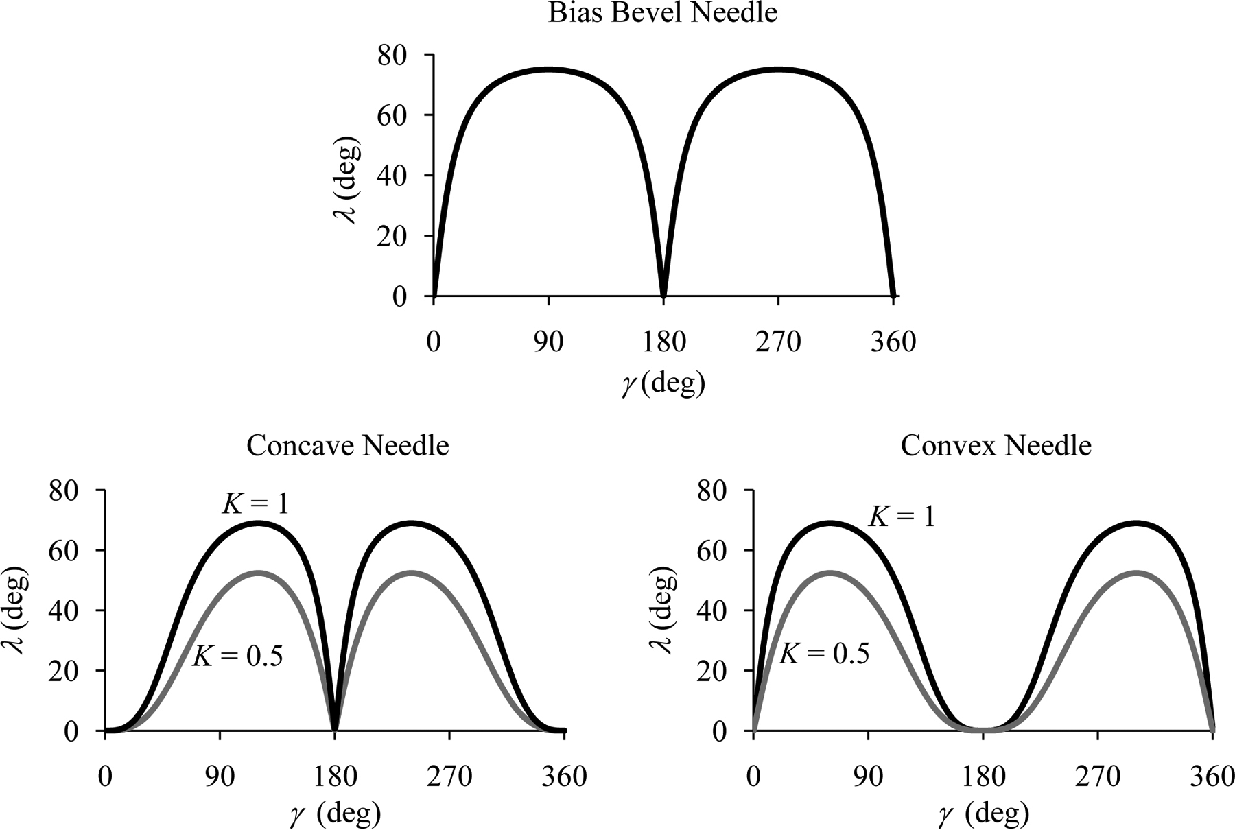
Inclination angle for bias bevel, concave, and convex needles given ro = 1 mm, K = 0.5, K = 1, and ξ = 15°.
Convex needles contain an extremely low inclination angle around γ = 180°, whereas the concave needle’s inclination angle quickly increases around γ = 180°. The bevel needle’s inclination angle profile is identical at the top and bottom of the cutting edge, whereas curved surface needles allow for differing inclination angle profiles. Therefore, the curved surface needles allow for greater flexibility in designing the inclination angle around a needle tip.
Rake angle
The rake angles of concave and convex needles are found using equation (8), and results are shown in Figure 9. Concave and convex style needles have the same rake angle profile given a phase shift of 180°. It is shown in Figure 9 that higher K values create higher rake angles.
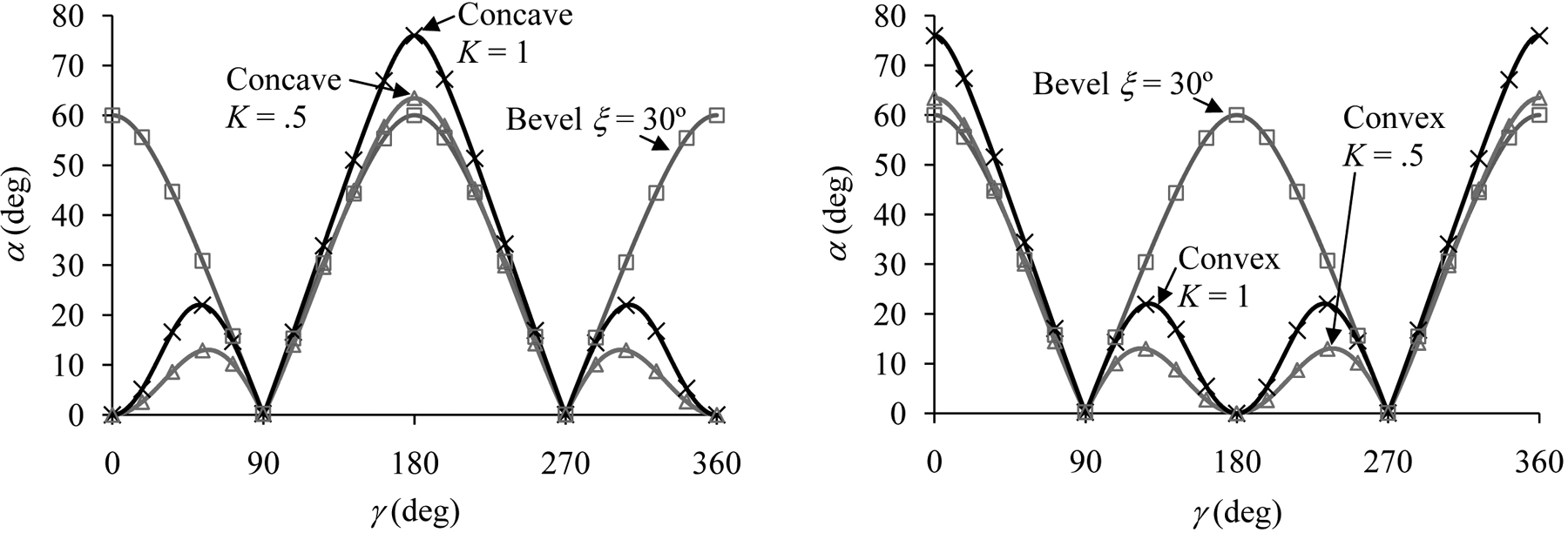
Rake angle for concave, convex, and bias bevel needles given K = 0.5, K = 1, and ξ = 30°.
Compared to a regular bias bevel needle the curved surface needles have a drastically different rake angle profile, as shown in Figure 9. The curved surface needles contain three relative maxima in rake angle, the positions and magnitudes of which differ depending on the K value and the type of needle, concave or convex. The convex needle contains a rake angle α = 0° at the top of the cutting edge (γ = 180°) while the concave needle contains a maximum rake angle at γ = 180°. The bias bevel needle contains identical rake angle values at the top and the bottom of the cutting edge. This symmetry creates a lack of flexibility in designing the needle tip rake angle.
Insertion length and needle tip area
Figure 10 shows A upon needle tip insertion for 18-gauge ultra-thin wall (ri = 0.559 mm) multi-plane symmetric needles with a bevel angle of ξ = 30° and P = 1, 2, 3, and 4. L is shown in Figure 10 as the insertion depth at the point of complete needle tip insertion.
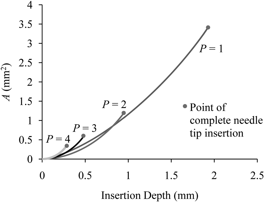
Needle insertion depth and inside area of 18-gauge ultra-thin wall (ri = 0.56 mm) multi-plane symmetric needles given ξ = 30° and P = 1, 2, 3, and 4.
There is a drastic change in L and A of the needle tip depending on the number of planes used to form the symmetric needles. Higher P values lead to lower final A and L values. Biopsy performance experimentation is necessary to determine the effect A and L have on the efficiency of the needle tip cutting operation.
Needle tip insertion force
Needle tip force model
Limiting needle insertion force lessens tissue and target deflection and increases biopsy sample length. 14 This allows for significantly better cancer detection in the case of prostate cancer. 3 Limiting biopsy sample length variation allows for consistent results during the procedure, and is also important.
Moore et al.
15
developed a hollow needle tip initial cutting force, FN, model that showed lower inclination angle leads to lower cutting forces and rake angle has very little effect on cutting force for thin needles. To develop this force model 16 blades of varying rake and inclination angles were inserted into bovine liver 10 times each and the specific force of this insertion was determined as a function of the results,
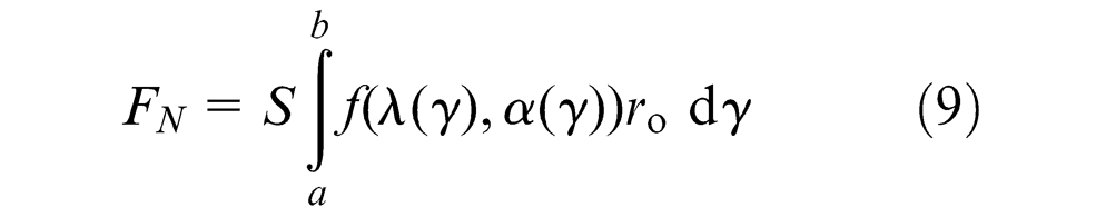
S is the scale factor needed to translate experimental flat blade results to results of curved needles, and was experimentally found to be 1.26. 15 Equation (9) is valid for needles having no leading edges where cutting occurs only around the needle circumference, which is valid for all single curved and single flat plane needle tips.
The specific force function determined by Moore et al.,
15

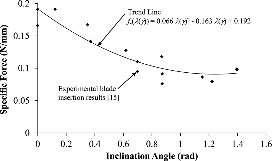
Inclination angle effect on specific force during blade insertions performed by Moore et al. 15
This model is applicable if
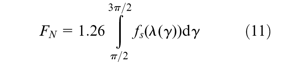
FN can be found by combing equations (9) and (10) as shown in equation (11) when assuming the front half of the needle is actively cutting the tissue, a = π/2 and b = 3π/2 radians, r = 1, and S = 1.26 as previously experimentally determined 15
It is possible that both A and L play a role in the cutting force. However, this relationship has not yet been established and will be the focus of future work.
Force model results
The concave needle in Figure 12 is shown to have a lower specific force on the front half of the needle, 90° < γ < 270°, than both the convex and bias bevel needles. Equation (10) is applied to a flat plane bias bevel needle of ξ = 30°, a concave needle of K = 1, and a convex needle of K = 1 as shown in Figure 12. The specific force around the front half of the needle tip plays an important role on the needle insertion force.
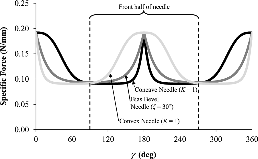
Predicted specific force on a concave needle, bias bevel needle, and convex needle.
Based on equation (11) the concave style needle will produce the least force of all the needles examined. Equation (11) is applied to a flat plane bias bevel needle of ξ = 30°, a concave needle of K = 1, and a convex needle of K = 1. The model predicts the concave needle will have FN = 0.39 N, the bias bevel needle will have FN = 0.44 N, and the convex needle will have FN = 0.558 N. Therefore, it is shown the concave needle is more ideal for biopsy than the convex needle and the bias bevel needle tip designs.
Conclusion
The rake and inclination angles were solved for curved surface needle tips and the parameters A and L were examined on plane style needles. A simplified force model equation was then developed and applied to bias bevel, concave, and convex needles.
The force model showed that the concave needles produce less force than both the convex needle and the bias bevel needle. Curved surface needle tips had the ability to create more variation in inclination and rake angles than traditional plane needles. Unlike the bias bevel needle the inclination and rake angles were not identical at both the top and bottom of the needle tip. This flexibility in choosing rake and inclination angles allows for greater freedom in creating optimized needle tip geometry. The values of A and L of symmetric plane needle tips were shown to vary drastically depending on the number of planes used to create the needle tips.
In the future needle studies will be conducted to determine exactly how λ, α, A, and L influence the biopsy performance, forces, and variability in performance. This paper presented a general model of needle force, equation (10); however, further modeling is necessary to determine an optimized needle tip geometry design that will increase the efficiency of the biopsy cut and thereby increase the doctor’s ability to make an accurate diagnosis.
Footnotes
Appendix
This work was supported by the National Science Foundation (NSF) [award CMMI #0825795], the National Natural Science Foundation of China [award number 50775119], and the University of Michigan Radiation Oncology Department.