
Abstract
This article presents empirical stiffness equations for a novel compliant needle mechanism that will aid in ultrasonic tissue cutting. Needles are an often used medical tool that cut tissue with minimal damage. Ultrasonic vibrational cutting has been shown to reduce insertion forces necessary to cut, thus minimizing deflections of the tissue and needle. A previous study has demonstrated that coupling this ultrasonic vibration with a compliant hinge generates a transverse cutting motion. This work explores the compliant hinge design and presents empirical stiffness equations that can be used to model the needles compliant motion. The empirical model prediction, when compared to experimental findings, is shown to have an average error less than 8% when the distance between the hinges is kept within 1.68 times the thickness of the hinges. With these equations it will be possible to optimize the compliant needle design for tissue cutting.
Introduction
In medicine, needles are some of the most widely used cutting tools. They are utilized for their ability to perform numerous procedures with minimal damage to the surrounding tissue. Some of these procedures include tissue biopsies, laparoscopic surgery, drug delivery, and interstitial brachytherapy. 1 Interstitial brachytherapy is a common treatment course for prostate cancer, the most frequently diagnosed cancer in men, with an estimated 164,690 new cases a year in the United States. 2 In this procedure, radiation seeds, approximately the size of a grain of rice, are placed by hand in specific geometric patterns around the tumor using ultrasound guidance. 3 Even with guidance, it is typical to only be able to achieve radiation seed placement of 2–3 mm from the target location. 4 It is a challenge to achieve a higher degree of accuracy due to needle deflections and tissue deformations.
Poor needle accuracy can be primarily attributed to the loading conditions on the needle as it cuts as well as the loading conditions on the tissue itself. Components of the insertion force act parallel to the insertion direction that cause the needle to deflect, leading to the needle cutting path to diverge. In order to minimize needle misplacement, it is necessary to reduce the forces acting parallel to the insertion direction. Several methods have been approached to reduce the insertion force, including reducing the diameter of the needle,5–9 optimization of the cutting planes,10–14 and the use of vibrational cutting.15–17
Vibrational cutting has long been used in traditional manufacturing to improve surface finish, tool wear, and chip formation 18 as well as reduction in cutting force. 19 Similar benefits from vibrational cutting have been demonstrated in the medical field as well. For example, ultrasonic vibration applied to a bone drill has been used to reduce cutting forces, 20 and harmonic scalpels have been used to cut and cauterize simultaneously. 21 Furthermore, Bi and Lin 22 demonstrated that use of high-frequency vibration can improve the precision and accuracy of the cutting operation.
In a recent study, Barnett et al. 23 coupled these axially applied vibrations with a unique compliant hinge design. They found that using an asymmetric design could generate a transverse cutting motion. This transverse cutting motion redirects the parallel cutting forces to a more perpendicular direction with respect to the target tissue, as seen in Figure 1. This redirection will reduce the forces the target tissue experience, thus, reducing the target tissue deflections. Furthermore, a significant decrease in the frictional force was demonstrated due to the increased crack length caused by the transverse cutting.
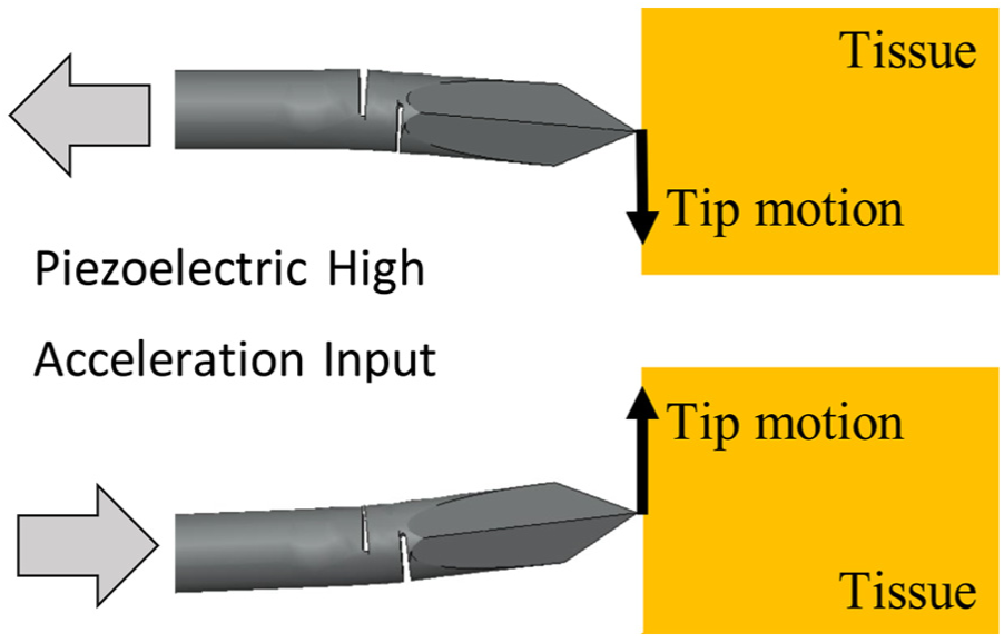
Transverse cutting motion from unique asymmetric complaint hinge coupled with ultrasonic axially applied vibration.
Understanding the rigidity in tooling, parts, and machines has been shown to be critical to understanding the performance of traditional manufacturing operations.24–26 However, little fundamental knowledge about compliant vibrational tooling is known due to its recent development. This includes a lack of knowledge about how tool flexural rigidity is impacted by compliant hinge design, the focus of this article. This article develops empirical models that predict compliant tool rigidity. Therefore, these models can be used by future tool designers to balance tool rigidity with necessary tool strength.
Compliant mechanism theory
Compliant mechanisms have gained favor in many applications, such as micro-electro-mechanical systems and x-ray lithography.27,28 Compliant mechanisms provide added benefits over their rigid-body mechanisms counterpart due to their cost reduction, increased performance, and reduction in parts, wear, weight, and maintenance. 29 These flexible members transfer input forces, energy, or displacements using stored strain energy in the flexible members of the mechanism. 27 A common monolithic compliant design is the flexure hinge. This flexible hinge acts like a revolute joint between two relatively rigid links, providing translational constraints, but allowing for rotational displacement. Compliant mechanisms used in needle design are not solely novel, previous research has demonstrated the benefits to using compliance to allow for steerable needles. However, this was accomplished with the use of an internal actuator 30 or from the beveled tip geometry. 31
Flexure hinges can be viewed as a system of discrete springs. For planer motion this relationship is defined as
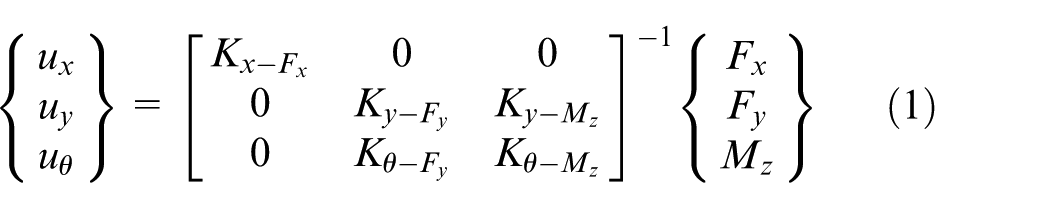
where ux, uy, and uϑ are the displacements in the axial, transverse, and rotational direction. Fx, Fy, and Mz are the force in the axial direction, the force in the transverse direction, and the moment in the rotational direction, respectively. The axial, transverse, and rotational stiffness are denoted by the Kx, Ky, and Kθ, respectively.
Work on describing the compliance of the flexure hinge is quite extensive. Some of the earliest efforts include the works by Burns and Crosssley, 32 who developed closed-form solutions of simple compliant mechanism. Paros and Weisbord 33 provided a compliance-based approach with their work on the symmetric-circular and right-circular flexure hinges. Smith et al. 34 provided closed-form compliance equations for the elliptical flexure hinge, further expanding the design space. Lobontiu formulated closed-form equations for the symmetric corner-filleted, 35 parabolic and hyperbolic, 36 and the symmetric-circular 37 hinge types. Howell and Midha 38 developed a simplified design method to model the flexure hinge as a pseudo-rigid-body model (PRBM) allowing for a convenient method to synthesis compliant mechanisms.
Finite element methods (FEMs) have been used to generate empirical stiffness equations. Empirical stiffness equations for a circular flexure hinge were compared to analytical solutions by Yong et al. 39 They showed that the percentage error of the empirical equations was less than 3% when compared to the analytical results. Meng et al. 40 used FEM to explore the existing stiffness equations for corner-filleted flexural hinges, again finding that the empirical models were able to generate an approximation with 6% error.
A typical flexural hinge design includes two symmetric notches cut from a single material creating a primary flexural member with a minimum thickness t, as seen in Figure 2(a). However, if we increase the longitudinal asymmetry by separating the two notches by a distance d, it can be seen that this primary flexure hinge will rotate as well as increase in thickness, Figure 2(b). For this hinge system, the overall compliance will be a product of the cross hinge as well as the parallel hinges. For some maximum ratio of d/t, defined as β, the primary flexural hinge will remain to be the cross hinge located between the two notches, after which the parallel hinges will be the primary flexure hinges. For this distance, it is appropriate to model the hinge as a lumped hinge system. However, it is necessary to determine when the assumption of a lumped hinge model is no longer valid.
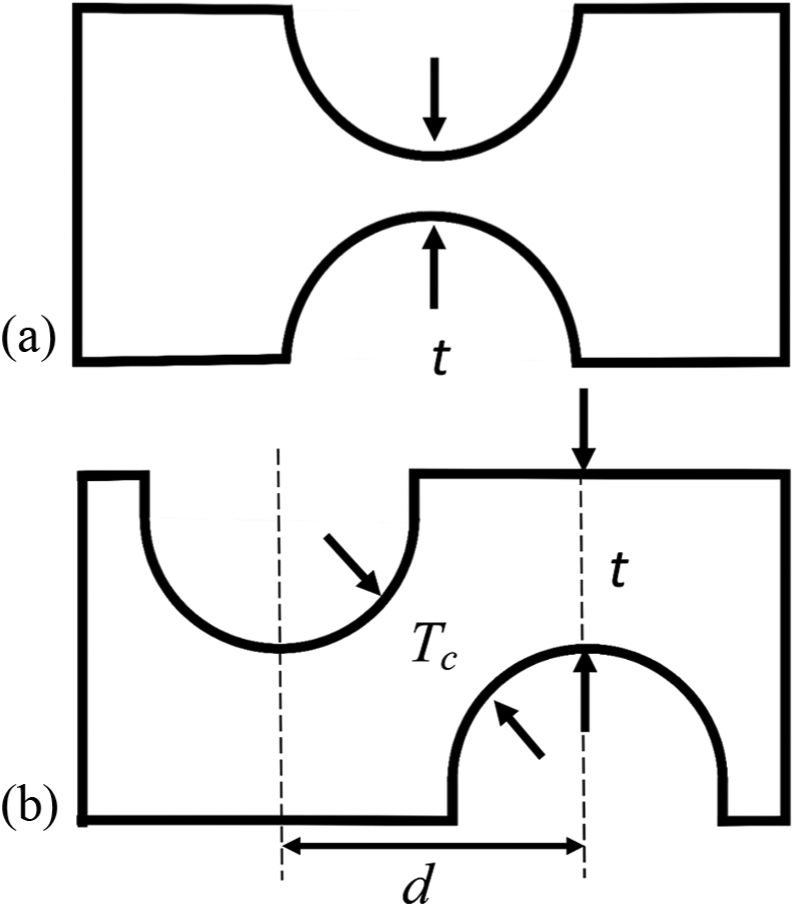
(a) Symmetric circular flexure hinge with minimum thickness t and (b) asymmetric flexure hinge system, where Tc is the cross hinge thickness, and t is the thickness of the parallel hinges.
The study described in this article uses FEM to develop empirical stiffness equations that describe the compliance of an asymmetric hinge design for a given geometry. As discussed, currently, there is a lack of empirical equations that describe the rigidity of this unique hinge, even though there are effective empirical equations to describe symmetric and single hinges. Therefore, to answer this gap in knowledge, an empirical equation model development method is chosen. With the compliance of the flexure hinge determined, it is then possible for future researchers to perform kinematic or dynamic analysis of the tool using the PRBM and efficiently determine the transverse cutting motion, which will make it possible to optimize the needle design for a reduction of the insertion forces.
Methodology
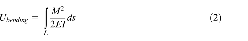
When the distance between the hinges becomes large, the primary flexure hinge will no longer be the cross hinge with a thickness of Tc but of the two parallel hinges with a thickness of t. Moreover, the constant cross-sectional rod section would significantly affect the bending if modeled as a lumped hinge mechanism. To determine when the transition from a lumped hinge model and a two longitudinal hinge models occurs, the elastic strain energy of a constant cross-sectional rod of increasing length with a pure end moment, Ubending, was calculated using equation (2); where M is the applied moment, E is the Young’s modulus, I is the second moment of area, ds is the differential length, and L is the total length.
This was then compared to the elastic strain energy of a cross hinge member with an increasing length, again using equation (2), where I for the cross hinge was determined to be
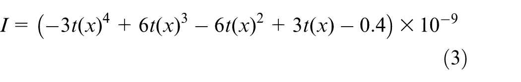
Where t(x) is defined as

By determining where the elastic energy of the two results cross, it is possible to determine which mechanism has a greater potential to contribute to the overall bending. This method showed that the cross hinge remains the primary flexure hinge until the distance between the hinges is greater 1.68 times than the thickness of the individual hinge.
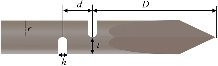
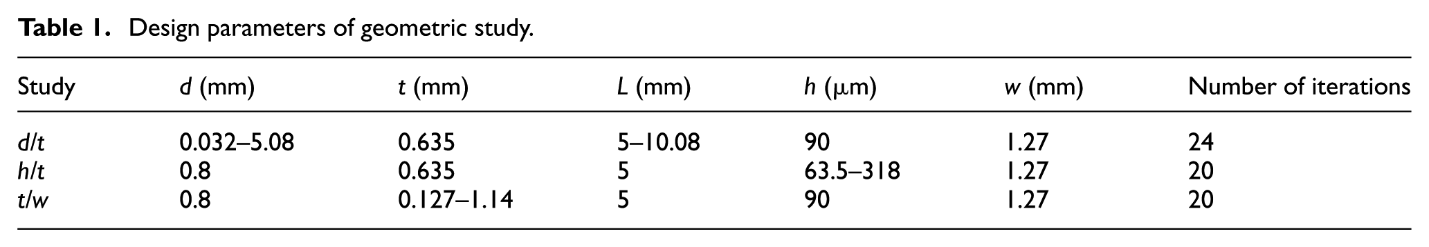
For the parametric study three non-dimensional design parameters were chosen due to their relationship with beam bending. These parameters and the ranges can be seen in Figure 3 and Table 1. From Figure 3, it can be seen that the geometric effects on stiffness of interests include length of the hinge h/t, the thickness of the hinge t/w, and the degree of asymmetry d/t. Also seen in Table 1, all geometries were held constant other than the geometries of interest.
Compliant needle design with parameters for asymmetric hinge study.
Design parameters of geometric study.
Empirical model simulation setup
ABAQUS was used to model the hinge designs. To simplify the simulations, the hinge was modeled as a cantilever beam as seen in Figure 4. All needles were modeled as AISI 304 stainless steel, a common material for needle manufacturing, with a Young’s modulus of 200 GPa, density (ρ) of 8000 kg/m3, and Poisson’s ratio of 0.29. To neglect any deformation outside of the flexure hinge, the sections left and right of the hinge had rigid-body constraints applied. To determine the axial stiffness, a load, Fx, of 1 N was applied at RP1. For the rotational stiffness a moment, Mz, of 1 N mm was applied at PR1 as well. For the transverse stiffness a load, Fy, of −1 N was applied to RP2. A moment Mfy, was applied to the center of the second hinge to negate the moment generated from the transverse load. All displacements were recorded at RP2 and used to calculate the stiffness in the respective direction using equation (1).
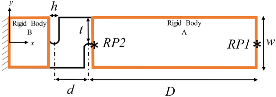
Simplified cantilever geometry for FEA parametric study.
For the mesh, quadratic hexahedral elements (C3D8R) were chosen. A mesh convergence study was performed to determine the optimal seeding for the geometry. It was determined that after a mesh density of approximately 700 elements/mm3, there is no appreciable improvement, so this seeding was chosen for all hinges design models.
Experimental model verification setup
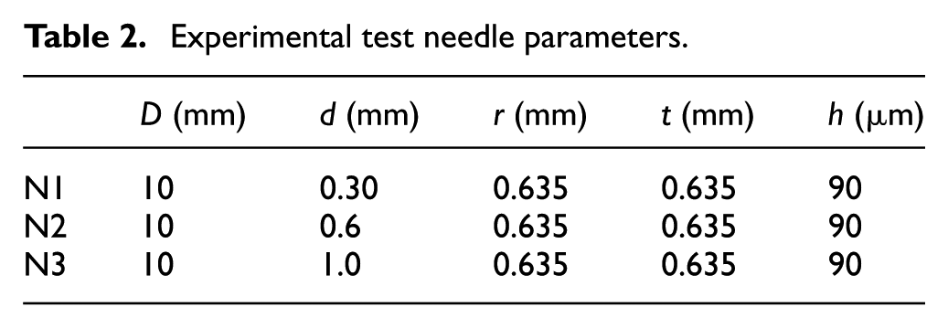
To verify the empirical equations a cantilever beam experiment was performed. Four ANSI 304 rods were manufactured using electrical discharge machining to create the flexure hinges. Table 2 shows the geometric parameters for the test. The test setup can be seen in Figure 5, where it can be seen that the needle is held fixed using a Jacobs’s chuck. The needle was positioned inside of the chuck so that the left most hinge began at the end of the chuck. A range of masses 10–100 g were suspended at a point located 10 mm from the nearest hinge. The transverse displacement was recorded using a fiber optic sensor (MTI-2100 Fotonic Sensor).
Experimental test needle parameters.
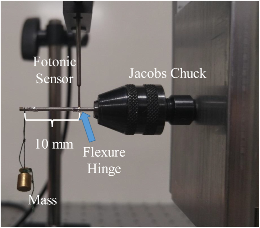
Experimental setup for model verification.
Simulation results
To generate empirical stiffness equations the calculated stiffness was plotted verses the non-dimensional design ratio. As expected, the rotational stiffness was the predominant factor in the stiffness matrix, four to five orders of magnitudes less than the axial and transverse stiffness. For this reason the axial and transverse stiffness can be neglected. Polynomial regression was used to generate the empirical equations with a minimum R2 of 0.90 used as the threshold to determine the nth degree of the polynomial. The general non-dimensional empirical stiffness equations will be defined as
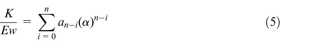
where Young’s modulus (E) and the diameter (w) of the rod are divided out in order to create a non-dimensional function. The design ratio, α, is multiplied by its corresponding polynomial coefficients.
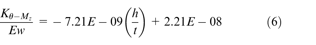
FEA empirical results for h/t study
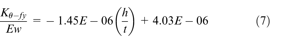
First degree polynomial equations (6) and (7) are the regression models for the rotational stiffness for the parametric study on the effect of the hinge length. Both have an R2 greater than 0.90 (equation (6), R2 = 0.96 and equation (7), R2 = 0.97), and both have a high significance for all regression coefficients (coefficient p values all less than 8.6E–15). The rotational stiffness was seen to decrease nearly linearly, R2 of 0.96, with the change in length of the hinge, seen in Figure 6. From Euler–Bernoulli beam theory, for a constant moment and constant flexural rigidity, EI, the rotation is going to be proportional to the length. With a maximum hinge length of 317 µm, the impact of the length of the hinge is minimal. This limitation is due to the necessity to keep the hinge of the compliant needle design to a minimum to reduce any potential tissue damage.
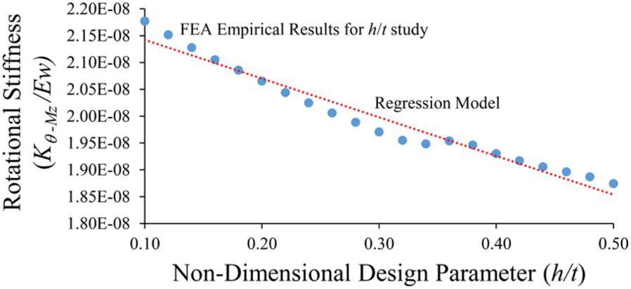
Rotational stiffness regression model for the non-dimensional design parameter h/t.
FEA empirical results for t/w study
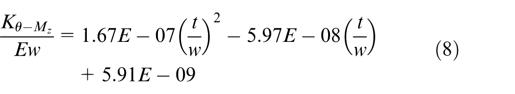
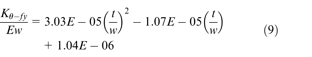
Second-degree polynomial equations (8) and (9) are the regression models for the rotational stiffness for the parametric study on the thickness of the parallel hinges. Both have an R2 greater than 0.90 (equations (8) and (9) both have R2 = 0.999), and both have a high significance for all regression coefficients (coefficient p values all less than 1.2E–5). In Figure 7, the rotational stiffness due to a pure moment is shown to be nearly parabolic. The hinge stiffness was greatly affected by the thickness of the hinges. As the thickness of the beams was increased from 10% of the overall diameter to 90%, the rotational stiffness was seen to increase over two orders of magnitude. Referring again to Euler–Bernoulli beam theory, the deflection is dependent on the second moment of area, I. It is then readily apparent that as the cross-sectional area becomes smaller, the deflection will increase. However, for very thin hinges the stress experienced would cause failure in the part so care must be taken.
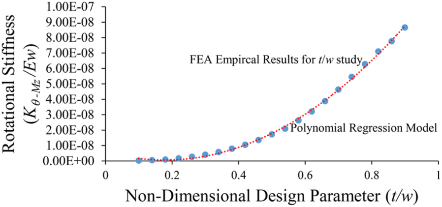
Rotational stiffness regression model for non-dimensional design parameter of t/w
FEA empirical results for d/t study
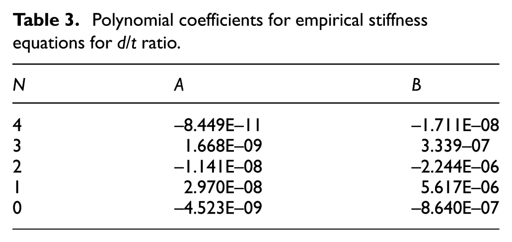
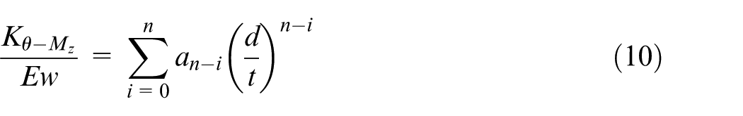
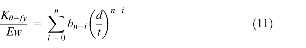
Forth-degree polynomial equations given in Table 3 and equations (10) and (11) are the regression models for the rotational stiffness for the parametric study on degree of asymmetry. Both have an R2 greater than 0.90 (equation (10), R2 = 0.97 and equation (11), R2 = 0.96) and both have a high significance for all regression coefficients (coefficient p values all less than 3.4E–5). The rotational stiffness demonstrates two distinct phases with a transition occurring around a d/t of 1.57, as seen in Figure 8. In Phase A, the stiffness of the hinge configuration is a product of the hinge thickness t and the cross hinge thickness Tc. It can be seen that as the distance d increases, there is a nonlinear increase in rotational stiffness. Phase B occurs after the point d/t of 1.57. In this phase, there is a nearly linear decrease in the hinge stiffness. This decrease can be contributed to the constant cross-sectional rod element separating the two distinct asymmetric hinges, and the cross hinge no longer being a significant contributor to the rotational stiffness. This result follows closely to the previously described elastic strain method that determined that the transition should occur at a β of 1.68. At this point it would be necessary to model the hinges separately and the entire mechanism as a serial chain mechanism using complaint equations such as the one derived by Lobontiu. 29
Polynomial coefficients for empirical stiffness equations for d/t ratio.
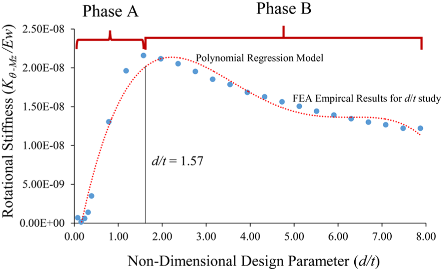
Rotational stiffness of the asymmetric hinge showing two distinct phases of the model.
Experimental results and model verification
To validate the empirical compliant equations, the end displacement of the previously described needle designs was calculated using the empirical equations. The results were then compared to FEM results as well as experimental result. As before, the simulation used AISI 304 stainless steel. For loading conditions, a transverse load equivalent to the experimental setup was applied at the end of the needle. The left end of the needle was fixed in all directions. Again, the end displacement was recorded at RP2. From Figure 9, it can be seen that the percent error for the empirical calculated displacement with respect to the FEM result for a degree of asymmetry, β, of 0.472, 0.945, and 1.575 had an average percent error of 2.1%, 3.18%, and 7.92%, respectively. This level of error is similar to previously reported empirical models. It can be seen that as β approaches the transitional point of 1.68, the error increases.
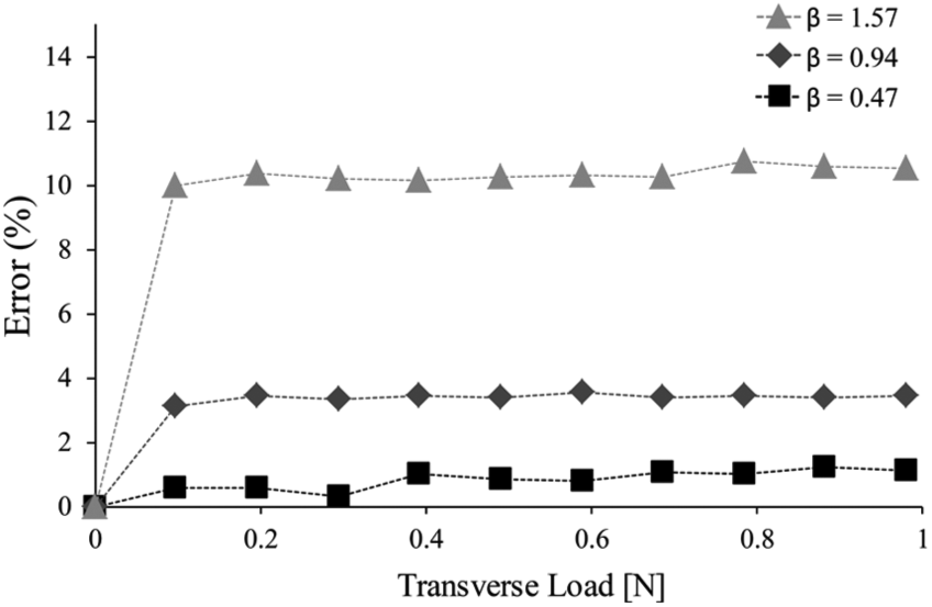
Percent error for β of 0.47, 0.95, and 1.57, with an average error of 2.1%, 3.2%, and 7.9%, respectively.
Discussion
The empirical equations developed provide information for how to effectively adjust the stiffness of a compliant hinge design. Increasing h/t had a very small impact overall on rotational stiffness, and therefore would not be an effective design parameter to target. Increasing t/w drastically increases the rotational stiffness. A very small t/w would also be a very weak hinge. Therefore, there would need to be design considerations to make sure t/w is large enough to provide the required strength. Increasing β created a unique two-phase increase and then decrease in rotational stiffness. Using the empirical model, the stiffness created by this parameter could be optimized for the desired application. Ensuring β < 1.68 is necessary if it is desired for the asymmetric hinge to be modeled and function as one hinge, rather than two separate hinges.
Conclusion and future works
This work presented an empirical compliance model for an asymmetric hinge to be coupled with ultrasonic axial vibration. Previous work demonstrated the feasibility of this type of hinge to generate transverse cutting motion. With the current compliance models, it will be possible to model the tools cutting plane in space. These stiffness equations were shown to have error typical of empirical models derived using FEM. However, it was shown that the empirical equations are best used when the asymmetry of the hinge is less than a β of 1.68. After this transition, it will be necessary to model the needle as a multi-hinge system.
The empirical equations will be used to model the kinematic and dynamic response of the cutting tool. This future work will have to incorporate stress considerations into the optimization, due to the compliance model not taking into account fatigue failure from the cyclic loading conditions.
Footnotes
Appendix 1
Declaration of conflicting interests
The author(s) declared no potential conflicts of interest with respect to the research, authorship, and/or publication of this article.
Funding
The author(s) disclosed receipt of the following financial support for the research, authorship, and/or publication of this article: This material is based upon the work supported by the National Science Foundation under Grant No. CMMI-1404916.