
Abstract
Depending on the intensity of mechanical and thermal loads during hard turning, compressive and/or tensile residual stress can be obtained. However, only compressive residual stress contributes to avoid crack initiation and propagation and increase fatigue life. In order to induce compressive residual stress in the workpiece surface and subsurface, cutting edge geometry is one of the most important influence factors. Taking this into account, the influence of new customized cutting edge geometries on the parameters of a hook-shaped residual stress profile (typical of a hard turning process) is investigated and possible causes for the encountered phenomena are explained. It was found that edge geometries, which provide an increase in contact length between tool and workpiece, lead to higher compressive residual stress in the subsurface and deeper affected zones.
Introduction
Manufactured parts for different branches, such as aircraft, chemical, automotive or oil and gas industries, are commonly subjected to high mechanical, thermal and chemical loads during service. In order to increase part lifetime, an adequate material must be selected and the machining process must be properly designed, as it influences the product characteristics significantly. Special attention must be paid to the surface features, as it provides the first resistance to the environment. Though surface roughness also affects the utility of finished parts and is frequently used by the industry as a quality control parameter, 1 residual stress also plays a very important role. In a review article, Suresh et al. affirm that many investigations show that tensile residual stress has a significant influence on the fatigue strength of the component. According to the same authors, smaller nose radii, low values of cutting speed and feed rate contribute to a favorable surface integrity, increasing fatigue life. 2 El-Axir 3 states that the propagation of the fatigue crack from the workpiece surface to the bulk due to tensile residual stress reduces the resistant section, contributing to component fatigue. Smith et al. 4 concluded that in order to hinder crack propagation and increase fatigue life, high compressive residual stress is recommended. Furthermore, Choi and Liu 5 verified that compressive residual stress induced by hard turning of AISI 1053 steel increased rolling contact fatigue life more than three times.
Depending on the intensity of mechanical and thermal loads during cutting, compressive or tensile residual stress is obtained. After measuring and modeling residual stress as a result of hard turning of bearing steel, Hua et al. affirm that compressive deformation occurs ahead of the cutting edge, while tensile deformation takes place behind it. Regarding to this, compressive residual stress is generated in the machined surface if the tensile deformation is greater than the compressive deformation. 6 According to Rech and Moisan, 7 in hard turning, not only the intense plastic deformation but also changes in the properties of the surface, such as hardness and microstructure, can contribute to the inducement of residual stress.
Many investigations in hard turning are related to the influence of cutting conditions and tool wear on residual stress. Dahlman et al. 8 and Javidi et al. 9 observed that due to high cutting forces and severe plastic deformation caused by high feed rates, residual stress in the subsurface becomes more compressive. In their work, Tang et al. 10 observed that high feed values damage the subsurface due to the intense material plastic deformation.
Revel et al. 11 also observed higher compressive residual stress after increasing depth of cut. Differently, Dahlman et al. 8 did not note any alteration of residual stress by changing this parameter. Jacobson 12 obtained this same conclusion and additionally observed that more negative effective rake angles and smaller nose radii lead to higher compressive residual stress. Revel et al. 11 and Kishawi and Elbestawi 13 investigated the influence of cutting speed and noted that when high speeds are used, material removal rate is high and most of the generated heat is taken away by the chips, reducing cutting temperature and tensile residual stress, as well.
Using a simulation model to predict residual stress after hard turning with minimum quantity lubrication, Ji and Liang 14 verified that heat transfer coefficient (considering the application of cutting fluid), depth of cut and tool rake angle are the main factors influencing the maximum compressive residual stress.
Dogra et al. observed tensile residual stress at the workpiece surface after hard turning with carbide and cubic boron nitride (CBN) tools. However, the higher thermal conductivity of CBN tools led to lower tensile residual stress values in comparison to the values obtained after turning with the carbide tool. The same authors noted compressive residual stress after hard turning interrupted surfaces, what was explained by the reduced temperatures during the process. 15
Concerning the influence of tool wear, Rech and Moisan 7 verified that worn tools tend to generate surface near tensile residual stress, since flank wear contributes to the increase of cutting temperature and thermal effects become predominant in comparison to mechanical effects at the workpiece surface. Liu et al. 16 obtained the same conclusions after hard turning of bearing steel and observed that as tool wear increases, the maximum compressive residual stress (in the bulk) is induced in a greater depth and with a larger magnitude. Dogra et al. 15 explain that the increase in tool flank wear causes the residual stress to shift from compressive to tensile values due to the thermal effect generated by rubbing between tool and workpiece. Chaudhari and Hashimoto noted the same phenomenon, but they observed compressive residual stress at deeper regions in the subsurface. They explain such results based on the small cutting area during hard turning, which limits the heat penetration to the workpiece. 17
Considering the material resistance in turning of hardened steels, low values of depth of cut and feed rate are selected in order to reduce mechanical and thermal loads during cutting. 16 In this context, chips are formed in a small region at the tool nose radius 18 and edge geometry has a great influence on material deformation and shearing process, playing an important role in inducing residual stress. 19 Matsumoto et al. 20 affirm that in hard turning, tool edge geometry has a dominant effect on the residual stress magnitude and depth in comparison with cutting parameters. Concerning the sensitivity of residual stress to edge geometry, its correct choice enables the inducement of compressive residual stress in the workpiece without changing cutting time, since parameter variation is not necessary.
Thiele and Melkote investigated the influence of tool edge geometry on residual stress for hard turning of AISI 52100 steel and observed that large-edge hone tools result in increased friction between tool and workpiece. Based on this, they affirm that machining with a large-edge hone tool leads to a larger tensile stress field behind the tool when compared to the stress field generated by the application of the small-edge hone tool. This larger tensile stress field causes higher compressive residual stress. 21 Agreeing with this analysis, Dogra et al. 15 found that chamfered and honed CBN tools applied in turning of hardened AISI 8620 steel produce low tensile residual stress. Hua et al. noted that by increasing edge radius and chamfer angle, burnishing becomes dominant and severe elastic and plastic deformation occurs in the workpiece material. This results in high levels of compressive residual stress in the workpiece. 6 Varela et al. 22 observed that cutting edges with combined chamfer and hone produce higher compressive residual stress at the workpiece surface in comparison to single honed tools, what was attributed to the significant plowing effect. Investigating the effect of different edge roundings on residual stress, Denkena et al. 23 noted that an increase in edge radius causes an increase in maximum compressive residual stress and an increase in the affected subsurface zone. The authors affirm that this effect can be related to the increase in passive force, which causes high mechanical loads on the workpiece surface. 23
The use of asymmetric edge roundings to induce residual stress in turning of hardened steel was investigated in a preliminary work, which demonstrated that asymmetric edge roundings have a great potential not only to induce compressive residual stress but also to increase the residual stress penetration depth. 24
The importance of inducing compressive residual stress after turning in order to enhance workpiece lifetime and the impact of edge geometry on generated residual stress as well as the lack of knowledge about the effect of different asymmetric roundings on workpiece surface integrity motivates the development of this work. Thus, cutting inserts with new customized microgeometries are applied in hard turning, and their influence on the parameters of a hook-shaped residual stress profile is investigated.
Material and methods
Polycrystalline cubic boron nitride (PCBN) inserts (90% PCBN, TiCN and Co as bond materials), SNMA120408 had their cutting edges prepared by grinding with the discretization method demonstrated in Ventura and colleagues.24,25 In this method, symmetrical and asymmetrical edge roundings are discretized by several chamfers, according to Figure 1(a). In order to characterize the edge, the geometry parameters Sα, Sγ, φ and Δr were used, 26 according to Figure 1(b). Considering an ideally sharp edge (A), the lengths Sα and Sγ correspond to the distances between this point and the point of detachment of the microgeometry profile from flank (B) and rake (C) faces, respectively. The form factor K = Sγ/Sα determines the tendency of the rounding to the flank (K < 1) or to the rake face (K > 1). The variable Δr determines the minimum distance from the microgeometry profile (D) to the point defined by the ideally sharp edge (A). The angle φ formed between rake face and Δr describes the intersection of Δr with the geometry profile.
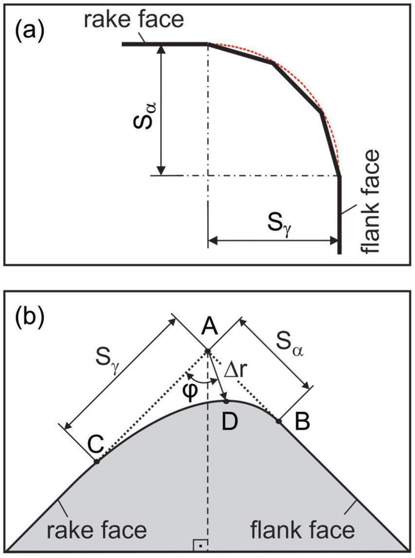
cutting edge geometry parameters, according to Denkena et al. 26
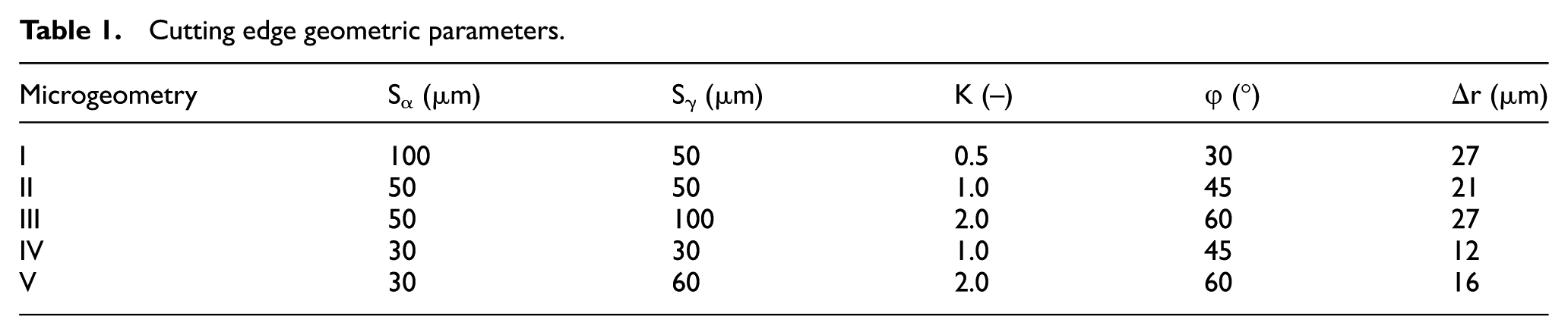
Five customized edge roundings were prepared for this work considering different sizes of Sα and Sγ and different form factors. Each of them was arbitrarily discretized by three chamfers. The explained characteristic geometric values are shown in Table 1.
Cutting edge geometric parameters.
In order to carry out the turning tests, a Gildemeister MD10S computer numerical controlled (CNC) lathe (maximum power of 50 kW) was used. Bars of hardened AISI 5115 steel (60 ± 2 HRC), with 60 mm diameter and 200 mm length, were machined by dry turning with constant cutting speed vc = 200 m/min, feed f = 0.1 mm and depth of cut ap = 0.1 mm. After mounting the insert, the following angles were defined: lead angle χr = 45°, rake angle γo = −10°, inclination angle λo = −10°, and clearance angle αo = 10°.
In order to avoid the influence of tool wear on the results, process forces were measured during turning a workpiece length of 20 mm (time interval of approximately 12 s) by a Kistler 9129AA three-component dynamometer connected to a Kistler 5015 charge amplifier. The signal acquired with a rate of 2500 Hz was filtered with a low-pass band filter (cutting frequency of 1000 Hz). Residual stress was measured in the same turned length by an X-ray diffractometer GE Seifert XRD3000P. For this, a Cr-Kα radiation with 30 kV and 35 mA is used to measure the peak Fe 211 in 9 psi-tilts within the range of ψ = ± 45°. The primary beam collimator (diameter d = 2 mm) generates at the lowest angle an ellipse with a maximum length of 1–4.5 mm. For measuring the residual stress depth distribution, material is gradually removed by electrolytical polishing using a device-type Kristall 620 of firm ATM Hydraulik GmbH. The depth corresponding to the removed material is measured by a stylus instrument Mahr Perthometer Concept. As the area of etching is a square with 8 × 8 mm2, there is no danger of a too large measuring spot. Rech and Moisan 7 reported that residual stress depth profiles after hard turning in axial direction have the same evolution as in circumferential direction. Borbe 27 also found similar residual stress depth profiles in axial and circumferential directions after hard turning. Therefore, it was decided to measure the residual stress only parallel to the cutting speed direction (circumferential). Moreover, due to the high speeds in this direction, more intense strains and residual stresses are expected. For characterizing the hook-shaped residual stress profile produced by hard turning with different edge geometries, four parameters were used, according to Figure 2: compressive surface residual stress (σo), subsurface maximum compressive residual stress (σmax), depth of subsurface maximum compressive residual stress (zmax) and depth of subsurface-affected zone (zt).
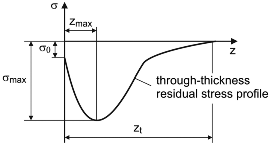
Hook-shaped residual stress profile and analyzed parameters.
Results and discussion
The increase in form factor and reduction of edge rounding (from microgeometry I to V) improve tool sharpness and lead to smaller chip deformation. This decreases, consequently, cutting forces, as demonstrated in Figure 3. A larger reduction in feed and passive forces in comparison to cutting force is noted because of the small feed and depth of cut applied. The higher values obtained for passive force in comparison to the other two force components are characteristic of hard turning and occur not only due to the selected cutting parameters but also because of the high hardness, which makes it difficult to penetrate the workpiece.
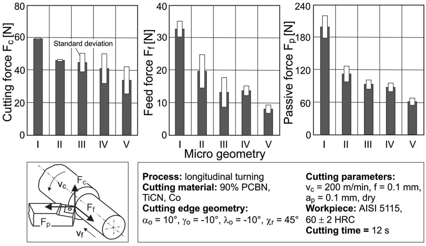
Variation in cutting forces with different edge geometries.
Standard deviation is calculated from the force values obtained in different turning tests. The high variability obtained in some cases is possibly related to variations in hardness in different workpiece positions, as no vibration or tool wear was observed during the experiments.
Parameters of residual stress can be directly correlated with the cutting forces, as depicted in Figure 4. Thus, the decrease in the form factor and increase in the edge rounding (from microgeometry V to I) lead to higher values of subsurface maximum compressive residual stress (σmax), lower compressive surface residual stress (σo), as well as high depths of subsurface maximum compressive residual stress (zmax) and of subsurface affected zone (zt).
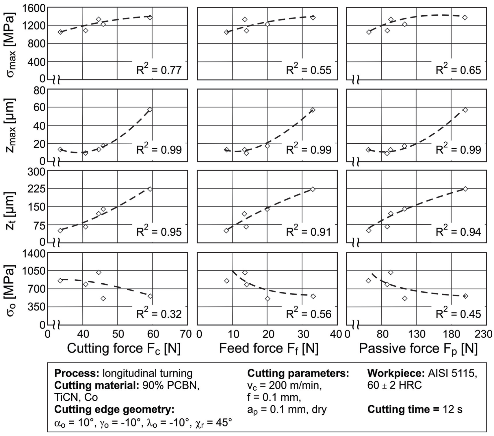
Correlation between residual stress parameters and process forces.
The points in the graphs correspond to experimental values, while the approximated curves are used only to illustrate the trends of the residual stress parameters in relation to the cutting forces. Nevertheless, the curves represent second-order polynomials, whose correlation coefficients are demonstrated. All compressive residual stress parameters investigated are positively related with cutting forces. However, the highest correlation coefficients are noted for zmax and zt.
The behavior of process forces can be correlated with residual stress parameters (Figure 4) due to the intense plastic deformation and the resulting predominance of mechanical loads during cutting, confirmed by the obtained compressive residual stress profiles. On one hand, an increment in forces increases all residual stress parameters related to the subsurface (subsurface maximum compressive residual stress σmax, depth of subsurface maximum compressive residual stress zmax and depth of subsurface-affected zone zt) mainly due to the higher values of passive force, directed perpendicularly to the workpiece surface. On the other hand, compressive surface residual stress σo decreases with higher force values. This reduction can have been caused by an increase in temperature in the workpiece surface during turning with cutting edges prepared with reduced form factors and larger edge roundings (both responsible for higher forces). These microgeometries increase the contact length between tool and workpiece, leading to higher friction energy and chip deformation.
According to the graphs, the depth of subsurface maximum compressive residual stress zmax and the depth of subsurface-affected zone zt are more sensitive to process forces. Large amounts of material flow under the edge when microgeometries with reduced form factors and large-edge roundings are applied, which leads to a thicker influenced zone and explains the greater variation in both residual stress parameters in relation to the cutting forces.
A large scatter of the compressive surface residual stress (σo) values is also observed in Figure 4 (low values of the correlation coefficients). In their investigations about inducement and relaxation of residual stress after machining processes, Denkena et al. 28 verified that scatter of compressive surface residual stress values is due to the measuring principle. The results are integral values for a material volume considered from the workpiece surface to an X-ray penetration depth of ≅5 μm in steel. Besides, surface roughness supports scattering effects of the measured values. As electrolytical polishing decreases surface roughness, scattering is reduced for residual stress measurements in greater depths.
Tool macro geometry, feed and edge geometry define the contact length between tool and workpiece. This length provides a measure of tool sharpness and, consequently, of chip deformation, friction and plowing effect. These factors influence cutting forces, which in turn affect residual stress in the workpiece. Therefore, a correlation between residual stress parameters and contact length should be verified. Contact length lk (Figure 5) can be obtained based on the defined microgeometry and on the mean chip thickness hm ≅ 22 μm, calculated according to the study by Meyer. 29 As chip thickness varies along the nose radius, mean chip thickness is calculated in this case by equating the cutting area based on the cutting parameters and the cutting area considering the geometric tool–workpiece contact arc: depth of cut × feed = mean chip thickness × contact arc.
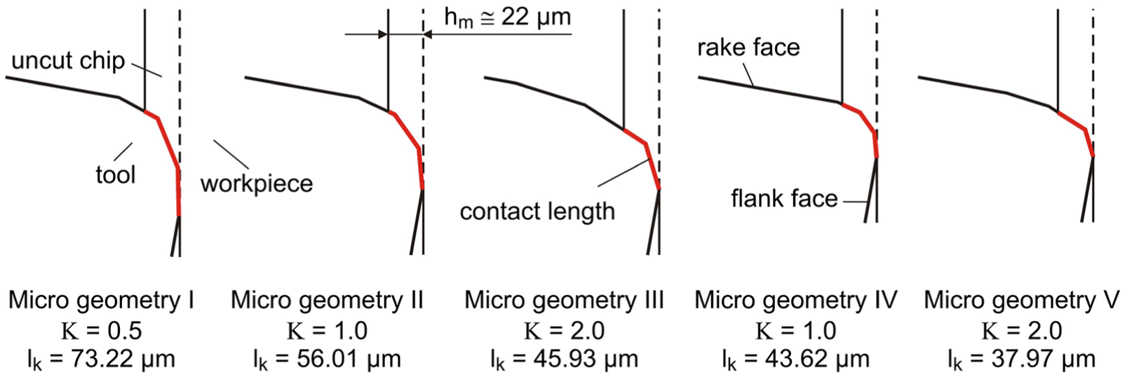
Contact length for different microgeometries.
The influence of the contact length on residual stress parameters is demonstrated in Figure 6. As well as in Figure 4, the points correspond to experimental values and the approximated curves (second-order polynomials) are used to illustrate the trends of the residual stress parameters in relation to the contact length. The correlation coefficients follow the same trend already observed in Figure 4. Higher values are noted for zmax and zt, while a larger scatter (lower correlation coefficient) is verified for σo.
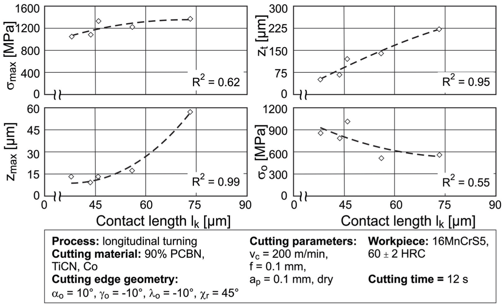
Variation in residual stress parameters with tool–workpiece contact length.
Higher cutting forces and longer contact lengths increase subsurface residual stress parameters and decrease compressive surface residual stress. This means that the contact length influences the mechanical load induced in the workpiece and the generated temperature at the workpiece surface. Considering the trends observed in the addressed process, the contact length can be used as a criterion to select tool geometry, aiming at achieving certain residual stress parameters.
In order to reinforce the proposed hypothesis, data from the literature are also analyzed (Figure 7). The goal is to show the trends of residual stress parameters obtained by different authors after varying the contact length in hard turning. The values from the literature are different from the values obtained in the experiments described in this article and present some scatter, as different workpiece materials (composition and hardness) as well as tool materials were applied in each case.
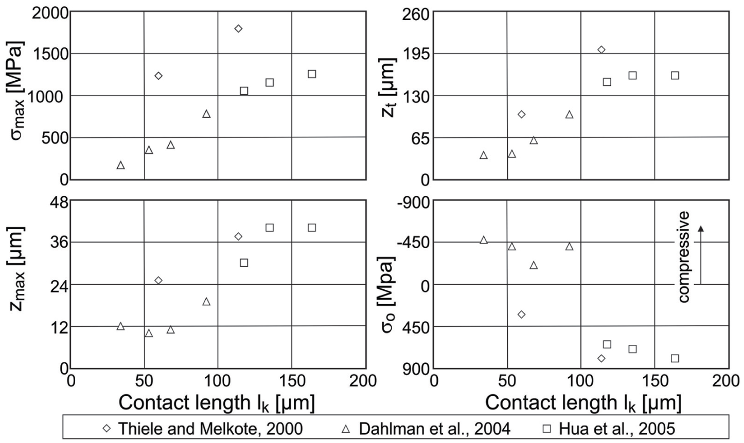
Hua et al. 6 and Thiele and Melkote 21 used different edge geometries (rounded edges: rβ = 20 μm, rβ = 50 μm, rβ = 100 μm, rβ = 121.9 μm; rounded edge + chamfer: rβ = 25.4 μm + b = 115 μm and γ = 17°), while Dahlman et al. 8 fixed microgeometry (rounded edge + chamfer: rβ = 20 μm + b = 100 μm and γ = 15°) and varied feed (f = 0.1, 0.2, 0.3 and 0.5 mm). All of them turned AISI 52100 steel with hardness 57 HRC, 56 HRC and 62 HRC, respectively. In all cases, low content PCBN inserts were applied and X-ray diffraction was used to measure through-thickness residual stress profiles in circumferential direction. Figure 7 shows the results combined in one single chart. The same trends for the variation of residual stress parameters in relation to contact length are observed, regardless of the variable used to alter contact length. This confirms the advantage of using the contact length as an auxiliary parameter to define tool geometry and as a consequence to achieve determined residual stress parameters.
Conclusion
In this article, the influence of customized cutting edge geometries on residual stress parameters obtained after hard turning was investigated. Due to the intense plastic deformation and resulting high mechanical load, compressive hook-shaped through-thickness residual stress profiles were obtained with all edge geometries. A correlation between residual stress parameters and tool–workpiece contact length, defined by the different microgeometries, was found. Considering these results, the contact length could be used as a criterion to select tool geometry, aiming at achieving certain residual stress parameters. Furthermore, an analysis of data from the literature confirmed that certain values of residual stress parameters can be obtained by altering the contact length regardless of the variable used to change it.
Footnotes
Appendix 1
Acknowledgements
The authors acknowledge Sandvik Coromant for supplying the PCBN cutting inserts.
Declaration of conflicting interests
The author(s) declared no potential conflicts of interest with respect to the research, authorship and/or publication of this article.
Funding
The author(s) disclosed receipt of the following financial support for the research, authorship, and/or publication of this article: The authors of the article gratefully acknowledge the financial support received from CAPES (Brazilian Federal Agency for the Support and Evaluation of Graduate Education), grant number BEX4202/10-4.