
Abstract
Polyetheretherketone-based tribological materials are nowadays firmly established in a wide variety of technical applications. In parallel, numerous publications on the improvement of tribologically usable PEEK materials by means of different fillers have been presented from academic research. This paper shows, using five tribological PEEK compounds provided by industry as examples, a comparative evaluation in a wide pv range in sliding contact against steel. Using a special test technique, so-called load increase tests, characteristic parameters such as the coefficient of friction in the stationary friction phase and the integral wear are determined and the wear manifestations are investigated. Element analyses lead to the conclusion that, beyond the addition of carbon fibers and solid lubricants, the best tribological properties can be achieved by adding a wide variety of inorganic fillers.
Introduction
Polymer-based tribomaterials are being used in an ever-increasing number of industrial applications, such as bearings,1–3 gears,4–6 and sealings.7–9 They combine good dry-running capabilities, high damping coefficients, and chemical resistance. These materials are most commonly used in combination with a steel counterbody such as a shaft. In order to maximize their tribological performance, high-performance polymer matrix materials such as PEEK are usually modified using various fillers and reinforcements. A significant improvement of the wear resistance can be achieved by reinforcing the matrix with various fibrous reinforcements. 10 Usually, carbon fibers are preferred for this purpose, 11 since glass fibers can break into fragments which have an abrasive effect. 12 The coefficient of friction can be reduced by adding solid lubricants such as graphite, 13 polytetrafluoroethylene (PTFE) 14 and molybdenum disulfide. 15 Both the friction and wear behavior can be improved by incorporating rigid inorganic particles into the matrix, which increase its strength and toughness. 16 If combined with reinforcing fibers, the increase in stiffness caused by the particles can reduce fatigue in the fiber-matrix interphase. 17 Also, the particles can move within the tribological contact, effectively causing a three-body-contact, 18 and accumulate in front of the fibers, reducing direct contact between the fibers and the counterbody. 19 These effects have been reported to become more pronounced with decreasing particle size.20,21
It has been demonstrated by several researchers that particularly good tribological properties can be achieved through synergistic effects by combining multiple of the aforementioned fillers. 22 A combination of PEEK and 10 wt.% each of short carbon fibers (SCF), graphite and PTFE has repeatedly been described as a favorable composition.23–25 However, its tribological properties are inconsistent, as the reported coefficient of friction ranges from 0.22 to 0.56 and the specific wear rate ranges from 0.5·10−6 to 88.5·10−6 mm3/Nm, depending on the load conditions. According to Zhang et al., 17 the performance of this compound can be further improved by the incorporation of silica nanoparticles. The coefficient of friction reported for this composition range from approximately 0.12 to 0.26 while the specific wear rate ranges from 0.4·10−6 to 1.3·10−6 mm3/Nm. Another potent composition has been identified by Oster, 26 who combined PEEK with SCF, graphite and both titanium dioxide and zinc sulfide particles. Oster achieved a coefficient of friction ranging from 0.05 to 0.5 and a specific wear rate ranging from 0.6·10−6to 2.2·10−6 mm3/Nm, depending on the load. Furthermore, Qi et al. have achieved a coefficient of friction ranging from 0.05 to 0.13 and a specific wear rate ranging from 0.13·10−6to 1.4·10−6 mm3/Nm using a PEEK compound comprising 10 vol.% SCF, 8 vol.% graphite and 2 vol.% silica nanoparticles. 27
Oftentimes, commercially available technology lags behind the state of the art in research to some extent. Therefore, it is interesting to determine the degree to which recent advances in polymer tribology have been transferred into products. The aim of this study is to evaluate several tribocompounds provided by different raw material manufacturers and compare their level of tribological performance to that described in the scientific literature for high-end compositions.
Experimental procedure
Materials and sample preparation
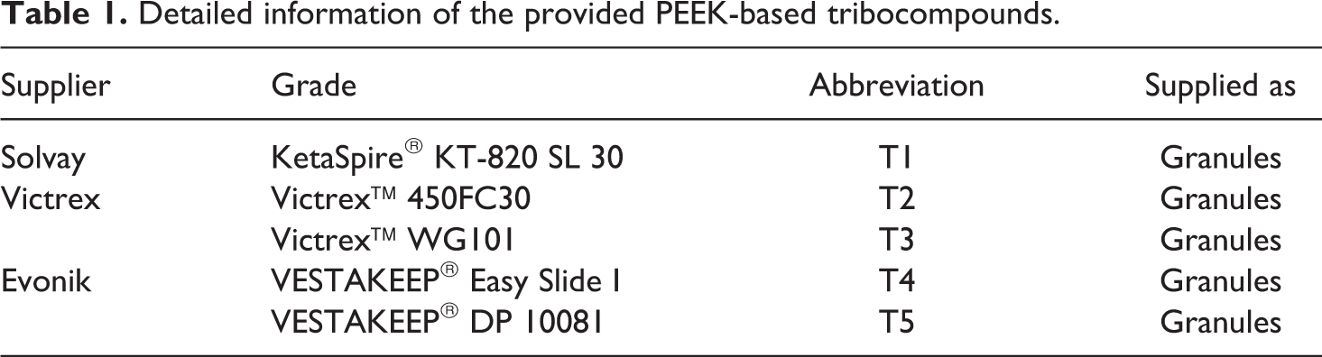
Five industrial grade tribocompounds were investigated and compared against each other with regard to their mechanical and tribological characteristics and performances. The compounds were provided by Evonik (Germany), Solvay (Belgium) and Victrex (UK) in the form of granules; an overview of all materials is given in Table 1.The granules were injection molded (ENGEL victory 200/80 spex, ENGEL Germany GmbH, Germany) to sheets with a thickness of 4 mm. An injection pressure of 1200 bar and cylinder temperature of 300/375/385/390/395°C were used, the tool temperature was set to180°C. Samples for tribological testing, sized 4 mm × 4 mm × 10 mm, as well as samples for tensile testing (size 1BB 28 ) and impact testing (standard small size 29 ) were cut out mechanically from the produced sheets.
Detailed information of the provided PEEK-based tribocompounds.
Testing methods
Quasi-static tensile tests were performed on a Zwick RetroLinetesting machine (Zwick GmbH & Co. KG, Germany) according to the standard DIN EN ISO 527 28 with cross-head speeds of 1 mm/min in the range = 0…0.25% and 50 mm/min at > 0.25%. The testing direction was defined parallel to the injection direction. An impact tester by Instron (Ceast 9050, Instron GmbH, Germany) was used for the impact tests according to DIN 53 453 29 for determining the impact resistance of the materials. The unnotched samples were tested flatwise with the impact energy set to 5 J. Both tensile and impact tests were performed under standard climatic conditions with air-conditioned samples.
Prior to the tribological tests, all samples were abraded with P240 and P1000 grinding papers, consecutively, to ensure a good contact of sample and counterbody which effectively reduces the running-in time. Any contamination was removed by cleaning both sample and counterpart with Isopropanol. ABlock-on-Ring (BoR) tribometer was employed (cf. Figure 1), on which the normal load to the samples was applied by a dead weight via a lever construction. 19 All tests were performed under dry sliding and controlled standard climatic conditions. The counterparts consisted of commercially available 100Cr6 steel rings (Schaeffler Technologies AG & Co. KG, Germany) with a surface roughness of = 0.2 µm. Normal and frictional forces were continuously recorded by a biaxial load cell with a sampling frequency of 0.5 Hz. Wear was evaluated by the weight loss of the sample over the entire test. Each test was conducted at least three times.
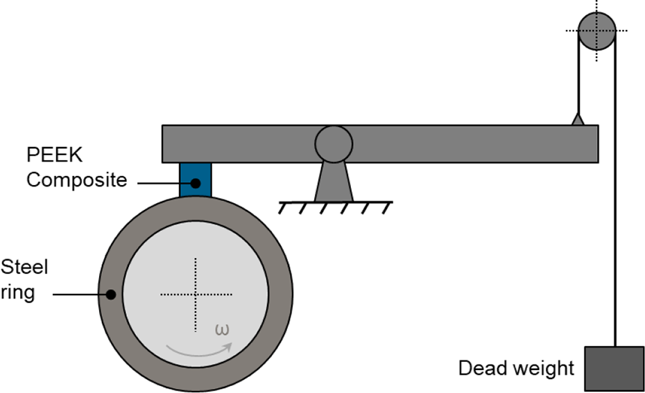
Schematic illustration of the BoR tribometer.
Velocity increasing tests at constant pressures of 1, 2, 4 and 8 MPa were performed to properly evaluate the compounds’ performances over a wide load spectrum. For each pressure value, the sliding velocity was increased incrementally from v = 0.5 ms−1 to 4 ms−1. The pv-range was selected such that no thermal failure of the polymer samples occupied, in order to ensure reliable measurements. The time in each increment was chosen such that the system was able to reach a steady state, which was defined as the friction coefficient having reached a constant level. The testing time for each material was equal. The system specific value for the COF in each stationary phase was determined by averaging the respective data points of the on-line measurement. The specific wear rate ws was calculated using the formula according to 30 :

WV is the wear volume, WM the mass loss of the pin,
After the tribological tests, the worn surfaces of representative samples and tribofilms were investigated via a light microscope (Nikon Eclipse LV100, Nikon Instruments Inc., Japan) to evaluate the differences in the wear manifestations. In addition, the pin surfaces were inspected by using a scanning electron microscope adopted with energy dispersive X-ray spectroscopy (SEM with EDX, SU8000, Hitachi, Japan) in order to reveal filler distributions and ultimately draw conclusions on the mechanisms behind the wear behavior.
Results and discussion
Morphology and mechanical characteristics
It is generally accepted that mechanical properties of fiber reinforced polymer materials are strongly dependent on the fiber orientation. The composite presents the best mechanical properties, if the load is parallel to the fiber orientation. For the studied tribomaterials, the carbon fibers are randomly distributed within the PEEK matrix, no preferential orientation of carbon fibers can be observed, as is shown in Figure 2.
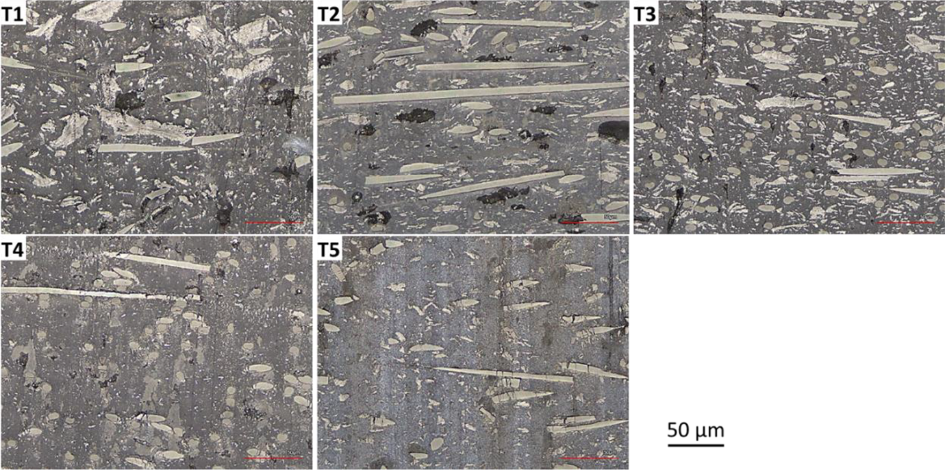
Dispersion of the carbon fibers within the PEEK matrix of different tribocompounds (micrographs of polished surfaces).
Figure 3 shows the tensile properties and impact strength of the different compounds studied. As can be seen, the Young’s modulus of the materials varied from approximate 6 to 10 GPa, in which T1 exhibits the highest modulus. With respect to the tensile strength, T3 presents the highest value among the compounds (cf. Figure 3(b)). However, it shows the lowest elongation at break, as is shown in Figure 3(c). On the other hand, the impact strength of T4 and T5is roughly 30% lower compared to those of the other composites.
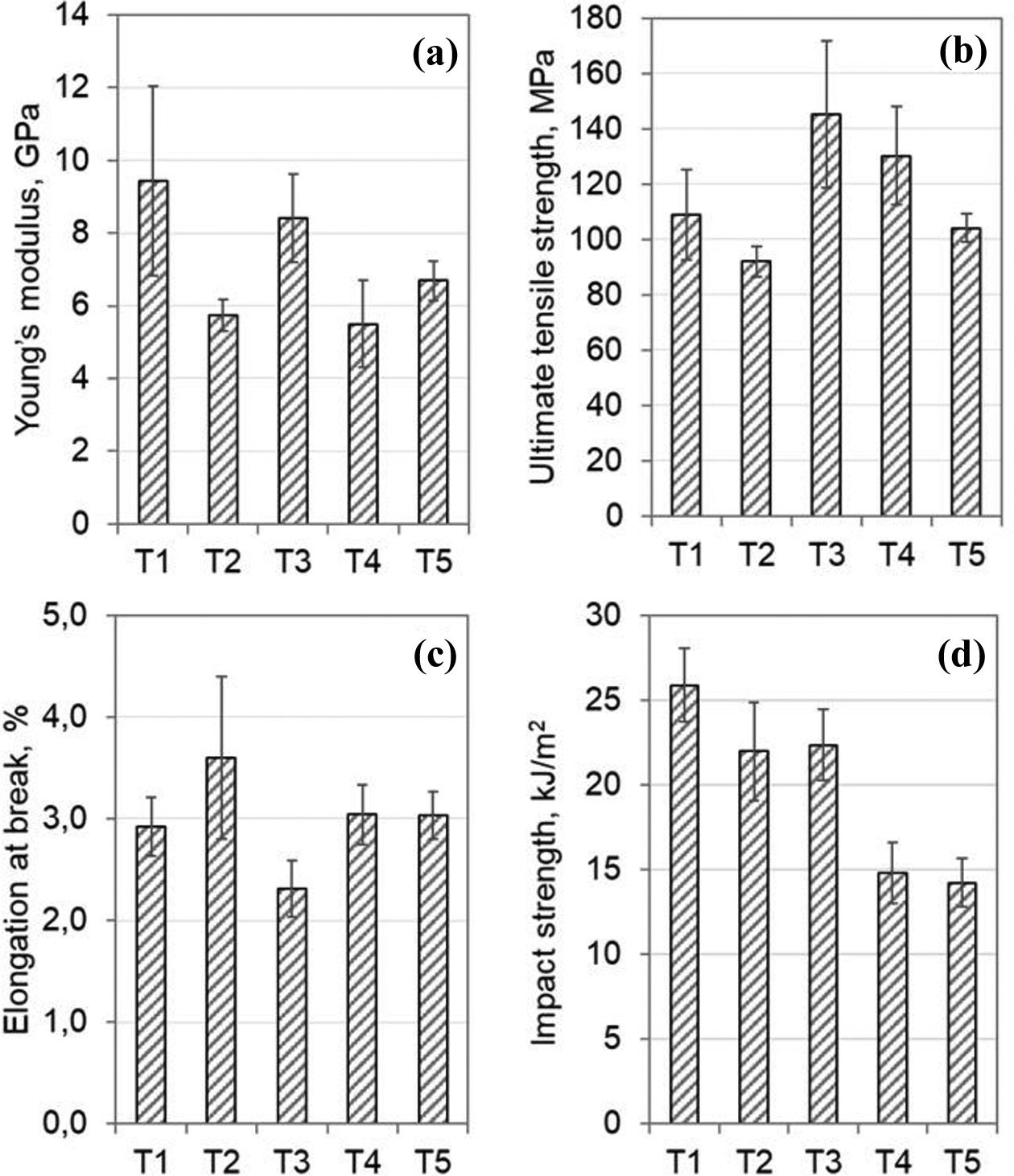
Young’s modulus (a), ultimate tensile strength (b), elongation at break (c), and impact strength (d) of the tribocompounds.
Tribological properties
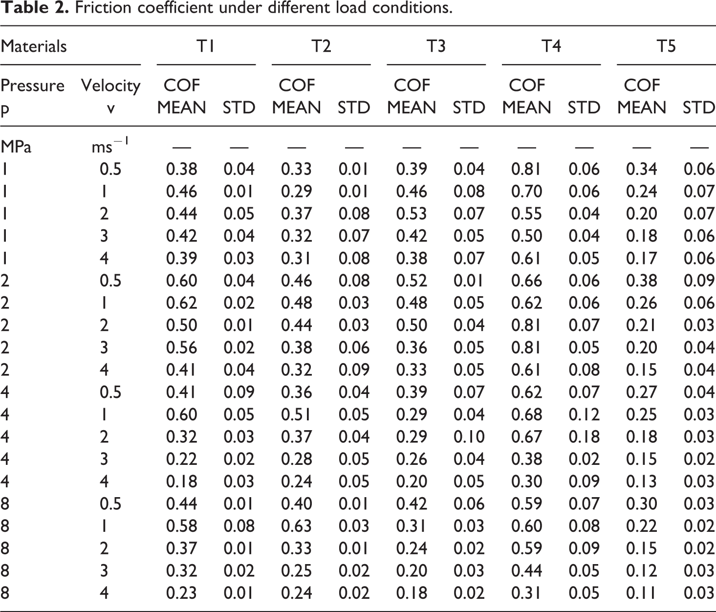
Friction coefficients of all the tribomaterials studied under distinct load conditions are summarized in Table 2. It is evident that T1, T2 andT3exhibit relative constant friction coefficient in the studied velocity range under a pressure of 1 MPa. In comparison, the friction coefficient of T5 gradually decreases from 0.34 to 0.17 with the increase in the sliding velocity. When the surface pressure is increased to 2 MPa, a decreasing trend of the friction coefficient of T1, T2, T3 and T5with increasing sliding velocity can be observed, too. At pressures of4 and 8 MPa, the friction coefficient of T1 andT2undergoes obviously a maximum. The intermediate maximum is observed at 1 ms−1. Similar to the dependence at 2 MPa, the friction coefficient of T3 and T5monotonically decreases with increasing sliding velocity. In comparison to the velocity influences, the friction coefficient of the studied tribocompounds shows distinct dependency on the pressure. It is interesting to note that, at low pressure up to 2 MPa, the friction coefficient of T5 exhibits almost no dependency on the pressure at identical sliding velocities. Further increase in the surface pressure leads to a slight decrease of its friction coefficient. As considering the friction behavior of other materials, no obvious dependence of friction coefficient on the pressure can be found. In summary, high pv-products lead to better friction performance of all the tribocompounds.
Friction coefficient under different load conditions.
Due to the fact that we applied a velocity increasing test approach in this study (cf. 2.2 Testing methods), only a mean wear rate over the whole sliding distance at different sliding velocities can be achieved. The results are shown in Figure 4. As is shown, for T1, T2 and T4, the mean wear rate undergoes a maximum at 2 MPa. In addition, it is worth to note the best wear performance of these compounds can be observed at 8 MPa. Unlike the three tribocompounds aforementioned, the mean wear rate of T3 monotonically decreases with increasing pressure. Again, it exhibits the lowest wear rate at high pressure. For T5, the mean wear rate gradually increases from 0.37 to 0.5·10−6 mm3/Nm when the pressure was raised from 1 to 4 MPa. Afterwards, a slight decrease in the wear rate is noticed with further increasing pressure.
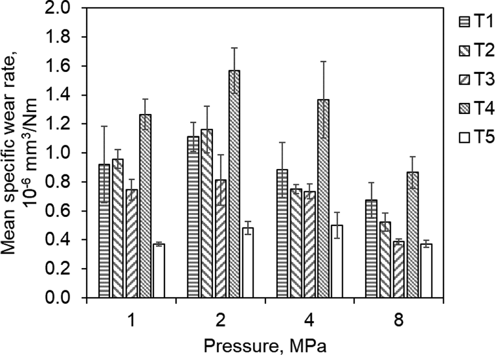
Dependence of the mean wear rate on the applied pressure of different tribocompounds.
With the intention of being able to compare the tribological performance of the compounds with a key figure, the mean value of the coefficient of friction and the specific wear rate were calculated for each material over the entire pv-range of 0–32 MPa·m/s and is shown in Figure 5. The error bars represent the standard deviation of one sigma. Since small values are favorite values in tribology, a position at the bottom left is desired in this diagram.
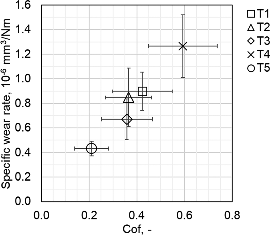
Mean value and standard deviation of the specific wear rate versus coefficient of friction of the compounds in the investigated pv-range.
Analysis of tribological mechanisms
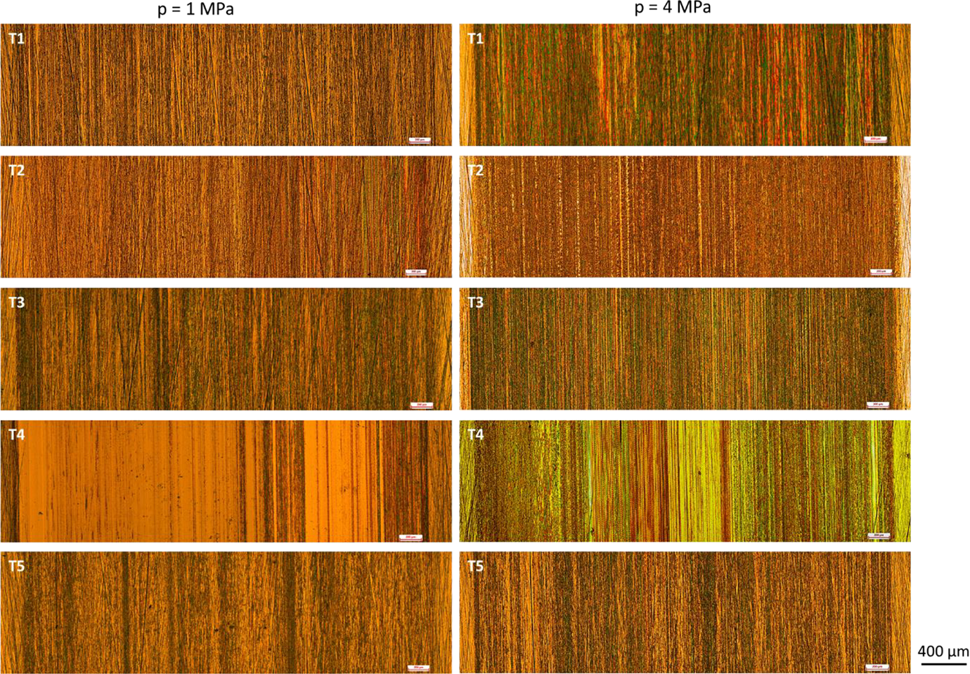
In order to elucidate the friction and wear mechanisms of different materials, the worn surfaces of both friction partners were analyzed and are shown in Figures 6 and 7. It is interesting to note that the tribocompounds show rougher surfaces at low surface pressure. Deep grooves resulting from the fractured carbon fibers and/or sharp asperities of the steel counterpart can be clearly observed on the worn surface (cf. Figure 6, left column), especially on the compound T4, which is closely related to its lower tribolgical performance compared to the other compounds. In contrast, the worn surfaces become much smoother once the pressure was changed toward higher values (cf. Figure 6, right column). Nevertheless, some deep grooves can be also observed on the worn surface of T4.
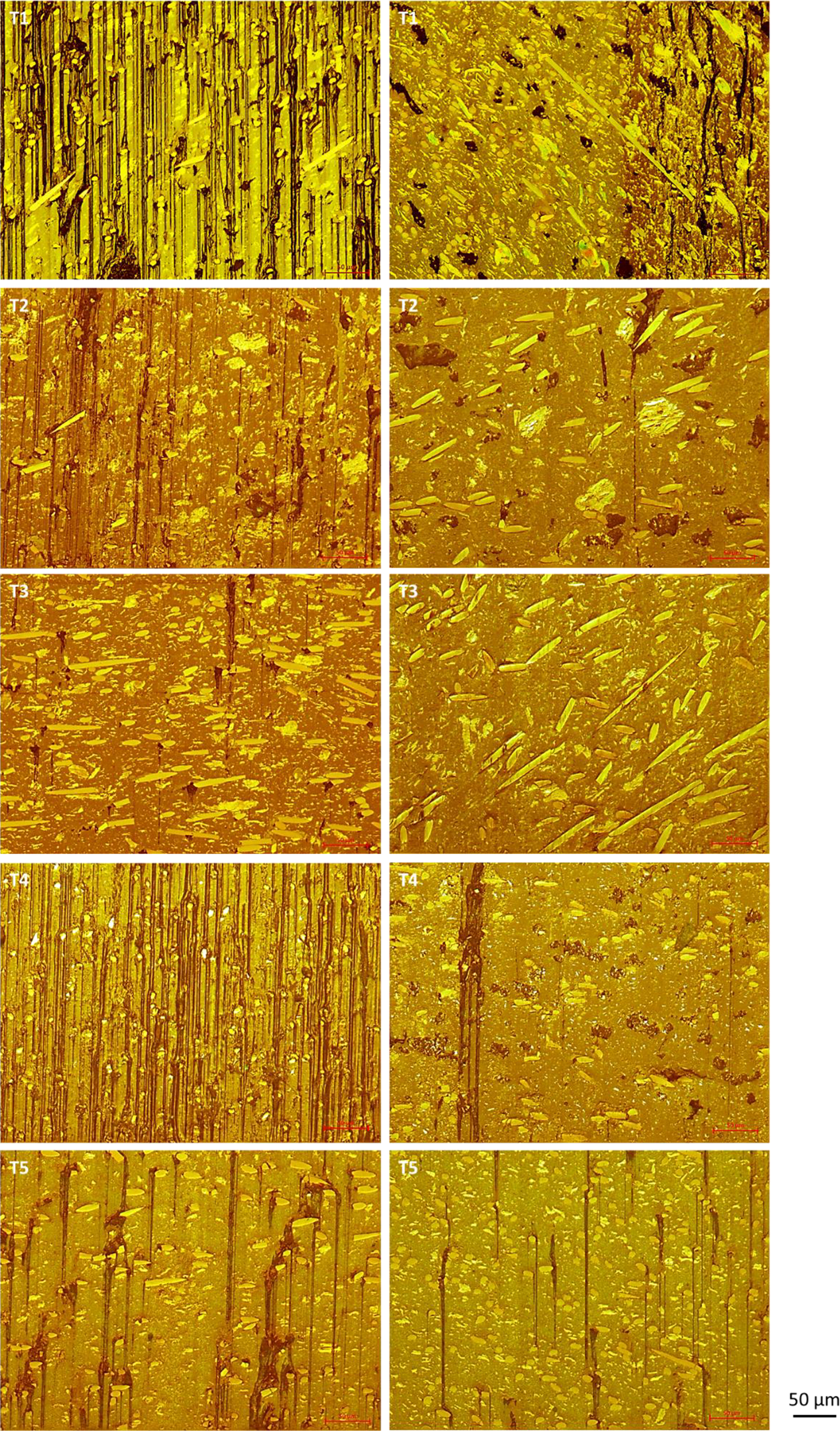
Representative worn surfaces of the tribocomposite produced at 1 MPa (left column) and 4 MPa (right column). Sliding direction is from top to bottom in the images.
Micrographs of the tribofilms formed on the steel ring surface at 1 MPa (left column) and 4 MPa (right column). Sliding direction is from top to bottom in the images.
With respect to the tribofilms formed on the steel counterface, it can be observed that almost no transfer of materials on the steel surface occurred during the sliding process for T4 compared to other tribocompounds, as can be seen from Figure 7. Besides T4, other tribocompounds present relative homogeneous tribofilm formation in a macroscopic manner.
Close inspection of the worn surface of T1 reveals that there are bright regions in front of the single carbon fibers (Figure 8) independent on the load conditions. EDX analysis of these regions show that they are particles containing Fe-element, which indicates that Fe-element was worn off from the steel counterpart and transferred onto the interface between the sliding pair. This correlates with the abrasion wear that results in high friction coefficient and wear rate of this compound. Similar worn surfaces are also observed at the interface between the sliding pair of T4 and steel (Supplementary Figures S1 and S2). However, no Fe-contained particles can be detected on the worn surfaces of T2 (Supplementary Figures S3 and S4). More interestingly, T3 exhibits similar pattern of the worn surface at low pressure like T1 and T4. Fe-contained areas on the worn surface can be clearly noted, as is shown in Figure 9. However, when the pressure is increased to high value of 8 MPa, no Fe-contained regions can be observed. Only C- and O-element can be detected on the contact region (Figure 9 and Supplementary Figure S5). In addition, T3 displays quite a smooth worn surface under the high-pressure condition. As considering the worn surface of T5, it is of great interest to detect diverse elements or in other words to recognize various elements indicating inorganic fillers (Figure 10 and Supplementary Figure S6). Beside the C- and O-element, there are also S-, Zn-, Si- and Ti-element. Presence of these fillers ensure the excellent friction and wear performance of T5. The corresponding tribological mechanisms of distinct particle filled hybrid tribocompounds have been reported in earlier studies. The main reasons are the improvement of the fatigue resistance of the polymer matrix by adding rigid particles, especially at the interface between fiber and polymer matrix, 17 the positive rolling effect of the particles between fiber and counterpart and deagglomeration of the inorganic particles under high load conditions17,18 and the protective effect of the particles in front of the fibers. 19
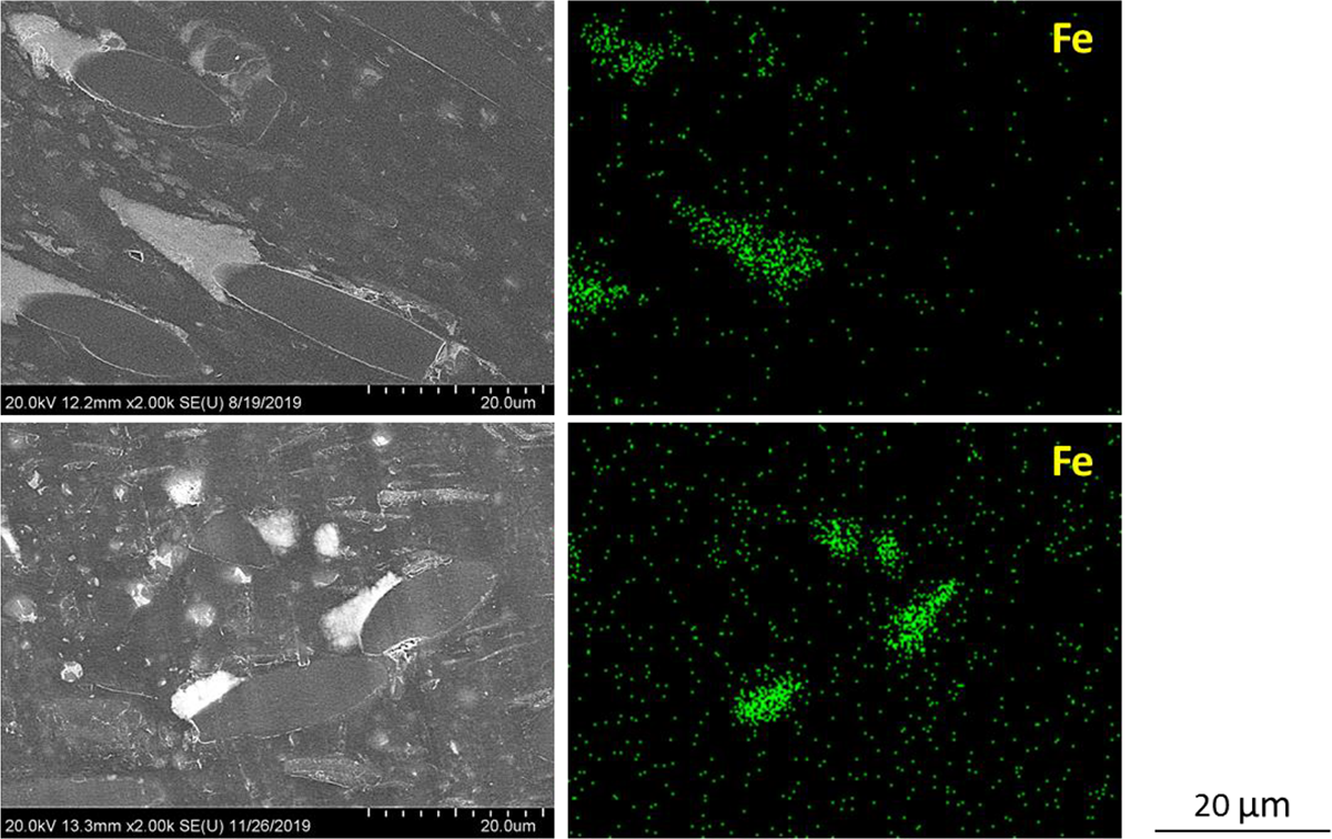
SEM and EDX images of the worn surface of T1 after being slid against the steel disc at 1 MPa (top) and 8 MPa (bottom).
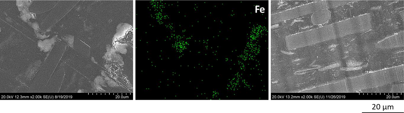
SEM micrographs of the worn surface of T3 after being slid against the steel disc at 1 MPa (left image) and 8 MPa (right image) as well as the elemental mapping of Fe-element at 1 MPa (middle).
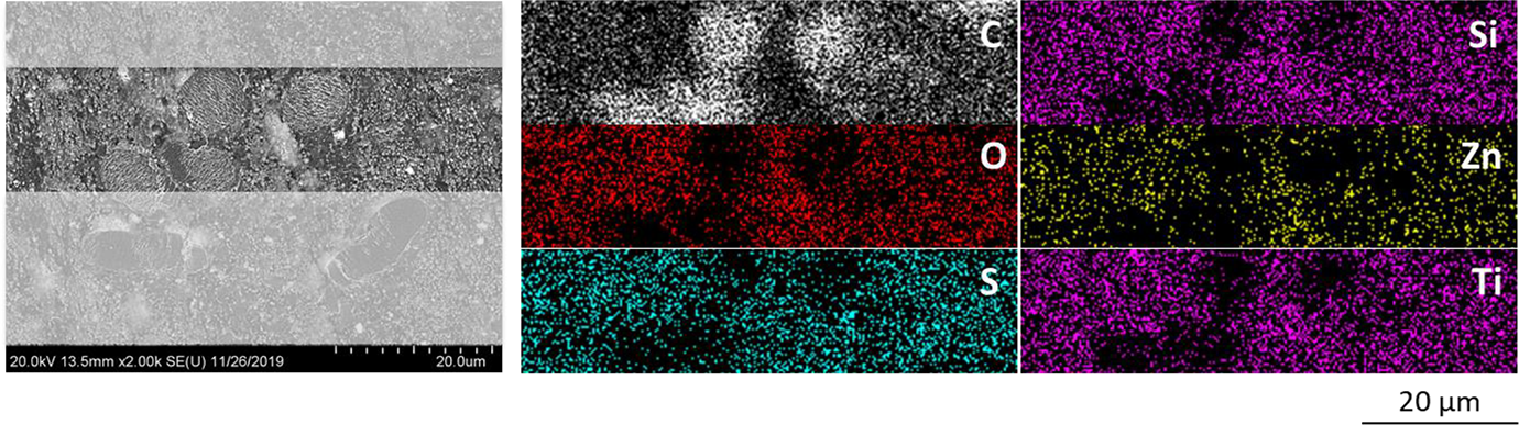
SEM and EDX images of the worn surface of T5 after being slid against the steel disc at 8 MPa.
Conclusions
Using the example of five industrial tribological compounds, the investigations show that the results published from science have been incorporated in different forms into tribological materials provided by industry. Even if the composition of the compounds is not known in detail, the microscopic images show that all materials are reinforced with carbon fibers. During the analysis of T3, no additional fillers could be clearly indentified, which may suggest a rather generic formulation, although this material exhibits a very decent tribological performance. In contrast, T1 and T2 are specified by their manufacturers to contain carbon fibers, graphite and PTFE, which is reminiscent of the materials described by Lu and Friedrich, 23 Zhang et al, 24 and Rodriguez et al. 25 This similarity is also reflected in the correspondence between the tribological properties determined in the experiments and the values reported by the aforementioned authors. The S-, Zn-, Si- and Ti-elements found in T5might suggest that chemical compounds/fillers similar to those used by Zhang et al, 17 Oster, 26 and Qi et al. 27 were incorporated in this material. This is underlined by the superior tribological properties of T5, as indicated by Figure 5.
From the mechanical investigations, it can be deduced that the materials T1 and T3 have the highest filler contents, since both materials show elastic moduli of >8 GPa. T3 and T4 exhibit the highest strengths, which indicates a more efficient reinforcing effect of the fillers in T4. The best impact strengths are found in the compounds T1, T2 and T3. The compound T3 therefore unveils the most balanced mechanical behavior. A number of publications show that the compressive stiffness of a homogeneous material in particular correlates well with the wear behavior. This is not the case with the polymer-based hybrid materials examined. If the materials are classified according to their wear resistance, material T3 is in second place just before T2.
The amount and type of fillers of T3 are obviously chosen so that both partners in the tribological system wear out, which can be demonstrated by the deposits of Fe(-compounds) on the plastic pin, at least in the lower surface pressure range. The same applies to materials T1 and T4. This effect is highly undesirable.
In conclusion, recent scientific findings regarding favorable compositions of high-performance tribocomposites appear to have been translated into products to a considerable extent. Thus, development engineers are provided easy access to state-of-the-art tribomaterials. The compositions of these materials have reached a level of complexity that uncouples their tribological potential from their mechanical properties. In fact, a balanced ratio of different fillers on different length scales seems to have a positive effect on the tribological behavior. This is likely caused by synergistical interactions between the individual fillers, which are evident from the appearance of the worn surfaces, such as a buildup of particulate material next to the fibers. Even if neither the microscopic nor the elemental analysis can identify the different fillers in terms of quantity and type, both investigation methods show a much more complex composition which leads to a comparatively much better tribological behavior, with regard to both the coefficient of friction and wear resistance.
Supplemental Material
Supplemental Material, sj-docx-1-jtc-10.1177_08927057211020054 - Performance and mechanisms of different tribological thermoplastic composites in sliding contact with steel
Supplemental Material, sj-docx-1-jtc-10.1177_08927057211020054 for Performance and mechanisms of different tribological thermoplastic composites in sliding contact with steel by Alois K Schlarb, Nicholas Ecke, Sebastian Kamerling, Yuxiao Zhao and Leyu Lin in Journal of Thermoplastic Composite Materials
Footnotes
Acknowledgements
The authors thank Evonik Operations GmbH, Germany, Solvay Specialty Polymers, Belgium, and VICTREX plc, Germany, for providing the experimental materials. We also thank Dr. S. Wolff, Nano Structuring Center (NSC), Technische Universität Kaiserslautern (TUK), for her help with the SEM and EDX analyses.
Funding
The authors disclosed receipt of the following financial support for the research, authorship, and/or publication of this article: We acknowledge the German Research Foundation (DFG) for the financial support of the research through grant SCHL 280/33-1.
Supplemental Material
Supplemental material for this article is available online.
References
Supplementary Material
Please find the following supplemental material available below.
For Open Access articles published under a Creative Commons License, all supplemental material carries the same license as the article it is associated with.
For non-Open Access articles published, all supplemental material carries a non-exclusive license, and permission requests for re-use of supplemental material or any part of supplemental material shall be sent directly to the copyright owner as specified in the copyright notice associated with the article.