
Abstract
Tidal turbine blades require thick-sections (10 - 100 mm) to withstand challenging operating conditions and high loads. The growing demand for sustainable materials is driving interest in recyclable liquid thermoplastic resins. These room-temperature processable resins may, in time, rival thermosets as the material of choice for blade manufacturing. Like other liquid resins, their use in thick-laminate production proves challenging as heat generated during polymerisation must be controlled to avoid boiling and defects. Although innovative low-exotherm grades are now available, their behaviour in thick-laminate manufacturing remains poorly understood. This study provides novel insights into the exothermic polymerisation profiles of two low-exotherm grades (Elium® 188 XO and Elium® 191 XO/SA). Industry-relevant findings on process times are also reported to guide their implementation. Five thermocouples embedded in each 10-ply laminate tracked temperature evolution over 12 hours. Elium® 188 XO reached a higher exothermic peak temperature (86.5°C) than Elium® 191 XO/SA (63.2°C). Nonetheless, both maximum temperatures remained below their respective boiling points, indicating minimised risk of exotherm-induced defects. A delayed exothermic reaction in Elium® 191 XO/SA extended its process time, implying a slower manufacturing rate. The enhanced understanding of the polymerisation behaviour of liquid thermoplastic resins in thick-section laminates will allow researchers and practitioners to establish their suitability for tidal turbine blades.
Keywords
Introduction
Tidal energy has considerable potential as a predictable renewable energy resource. It is projected that, by 2050, UK electricity demand will rise to between 550 and 680 TWh/year, compared to 317 TWh in 2023.1,2 The UK’s practical tidal energy resource is estimated at 34 TWh/year, accounting for 50% of Europe’s resource.1,3 Rotor blades are a key component of most tidal stream energy converters. Despite being similar in structure to wind turbine blades, tidal turbine blades operate in very different conditions. In addition to being continuously submerged in saltwater, they are subjected to much higher loads, necessitating the use of thick-section laminates (10 - 100 mm), especially in the root section of the blade.4,5
The majority of tidal turbine blades are manufactured from fibre-reinforced thermoset polymer composite materials using vacuum infusion processing. These typically comprise glass (GF) or carbon fibres (CF) as reinforcement within an epoxy matrix.4–8 Thermosets have traditionally been the preferred matrices for composite applications due to their excellent manufacturability, good mechanical properties, environmental resistance, and relatively low cost.9–11 The cross-links that confer good mechanical and environmental performance typically prohibit melting and reshaping, which are critical features of many conventional recycling processes available to thermoplastics. The growth of the onshore and offshore wind industries has highlighted that using thermoset resins in the manufacture of blades is not a sustainable practice. Since these materials are currently not recyclable at industrial scale, blades that cannot be repurposed are predominantly incinerated or landfilled. Though the tidal energy industry presently produces low volumes of waste due to fewer deployed devices, it is estimated that 1 GW of tidal energy capacity will generate approximately 6000 tonnes of blade waste at the end of service life (EOSL). 12 With deployment trajectories predicting 0.9 GW of installed tidal capacity in the UK by 2035, the potential waste generation cannot be overlooked. 13
Although thermoplastics offer superior toughness, impact resistance, and good out-of-plane properties, as well as reduced processing times, they are typically solid at room temperature.14,15 The subsequent requirement for high temperatures and pressures during melt processing limits their applicability.16–19 Recent material innovations in recyclable liquid thermoplastic resins (LTPRs), such as Elium® produced by Arkema, provide the potential for more sustainable material choices for composite blades.6–8,20–22 These acrylic-based materials offer a combination of advantages from both traditional thermoset and thermoplastic resins; they are initially low-viscosity resins that can be processed at low, ambient temperatures using established resin infusion techniques to produce recyclable parts with high strength, toughness, impact resistance and ductile failure behaviour.16,20,23–26 Furthermore, LTPRs offer potential cost advantages over comparable thermoset components, primarily due to shorter cycle times, reduced labour requirements, and lower energy consumption since post-curing is not required.27–29
Producing a laminate with consistent quality throughout the thickness is challenging in the manufacture of thick-section composite laminates. Conventional composite laminate manufacturing challenges such as incomplete wetting of fibres, insufficient ply consolidation and trapped air become more acute, potentially resulting in void formation, non-uniform polymerisation of material, and compromised dimensional stability in the thickness direction.5,30–32 One of the major challenges when manufacturing thick-section laminates is managing the heat generated by exothermic reactions, which can introduce defects, shape distortion and unwanted residual stresses in laminates due to temperature differences between plies, thus reducing the quality of laminates.5,19,31–35 This internal production of heat is due to the cross-linking of polymer chains during curing in conventional thermosets and the free radical polymerisation in monomeric thermoplastics such as acrylic LTPRs, which are both exothermic reaction types.25,33,36,37 While it is crucial to avoid excessively high exothermic peaks that can lead to thermal runaway, voids, and other defects, it is equally important to ensure that the part reaches sufficiently high temperatures to promote the formation of high-molecular-weight polymer chains. 38
Previous studies involving acrylic LTPRs have reported temperatures exceeding the resin’s boiling point (approximately 100°C) if no exothermic control agent is used in laminates thicker than 12 mm. This can lead to gas formation, voids and inconsistencies, resulting in a decrease in mechanical properties.25,34–36,39,40 These high temperatures also risk thermal runaway and a heightened chance of defects.25,34–36 Han et al. investigated the temperature evolution of three glass fibre/acrylic laminates during manufacture. 32 Laminates consisting of 4-, 8- and 12-plies, equating to thicknesses of 3.8 mm, 7.5 mm and 11.3 mm, were made using Elium® 150 (E150) with no control agent. Peak temperatures at the centre of the laminates were reported as 48.5°C, 62.5°C and 70°C, respectively, under ambient conditions. The void content in all laminates was reported to be less than 1%, with two types of voids identified: micro-voids within the fibre tows of the unidirectional (UD) fibre layers and meso-voids between the UD layers. While micro-voids were present in all three laminates, meso-voids were only observed in the thicker laminates (7.5 mm and 11.3 mm). 32
Several low-exotherm grades of acrylic LTPRs have since been developed, such as Elium® 188 XO and Elium® 191 XO/SA by Arkema. 41 These grades are formulated for use in the marine and wind industry where there are multiple instances of thick-section composite parts. 20 While both Elium® 188 XO and Elium® 191 XO/SA are rapidly gaining research attention,42–46 the exothermic polymerisation profiles of these resins during polymerisation in thick laminates must be further studied to gain insights into the temperature distribution trends and explore avenues for process optimisation.
Therefore, the aim of the current study is to comparatively assess the exothermic polymerisation profiles of two low-exotherm grade LTPRs during the room-temperature vacuum infusion and consolidation of thick-section laminates. Informed by the results of Han et al., a 10-ply laminate was selected to minimise the risk of a catastrophic exotherm and void generation. 32 The temperature evolution during vacuum infusion processing was measured and directly compared for the two resins. Single polymerised samples of each of the two low-exotherm resins were further investigated using Nuclear magnetic resonance (NMR) spectroscopy to evaluate monomer conversion.
This study provides novel and comprehensive data on the in situ polymerisation temperature distribution through laminates for low-exotherm LTPRs, offering timely insights into thermal management and process efficiency for sustainable industrial composite manufacturing. These findings address fundamental gaps in understanding how low-exotherm resins influence thermal polymerisation in thick-section manufacturing. This enhanced understanding will guide the design and implementation of effective quality controls, better enabling blade manufacturers to consider recyclable thermoplastic resins as sustainable alternatives to traditional thermosetting resins during material selection.
Materials and Methods
Materials
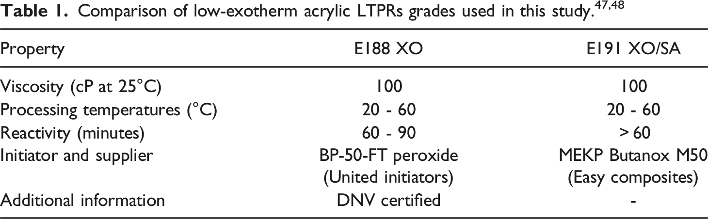
One laminate measuring 195 mm by 195 mm was created from each resin, combining the liquid thermoplastic with 10 plies of quasi-unidirectional (quasi-UD) E-glass fibre (GF) fabric, which contained an acrylic-specific sizing agent (Textile Structure 7009444; Johns Manville & SAERTEX). The total areal weight of the fabric was 1200 g/m2, consisting of 1152 g/m2 of 0° fibres with 35 g/m2 and 13 g/m2 of 90° fibres and synthetic stitching, respectively. For each laminate, the resin-to-initiator ratio was 100:3 by weight, and both were mixed for 5 minutes to ensure standardisation of the manufacturing process. A dibenzoyl peroxide initiator, BP-50-FT (United Initiators), was used for the E188 XO laminate, and a methyl ethyl ketone peroxide (MEKP) catalyst (Easy Composites) for E191 XO/SA. The polymerised thicknesses of the E188 XO and E191 XO/SA laminates were 9.5 ± 0.3 mm and 10.1 ± 0.5 mm, respectively.
Instrumentation
Five thermocouples were distributed through the thickness of each laminate to measure the temperatures at fixed intervals: 0% (bottom), 25%, 50% (middle), 75% and 100% (top), as shown in Figure 1(a). The welded tips of all thermocouples were positioned at the same position in x and y, highlighted in Figure 1(b). The air temperatures in the hood and resin inlet pot were monitored using additional thermocouples. (a) Cross-section of experimental setup. For clarity, layup is depicted before vacuum is applied with no insulation. (b) Position of interlaminar thermocouples placed on top of each ply.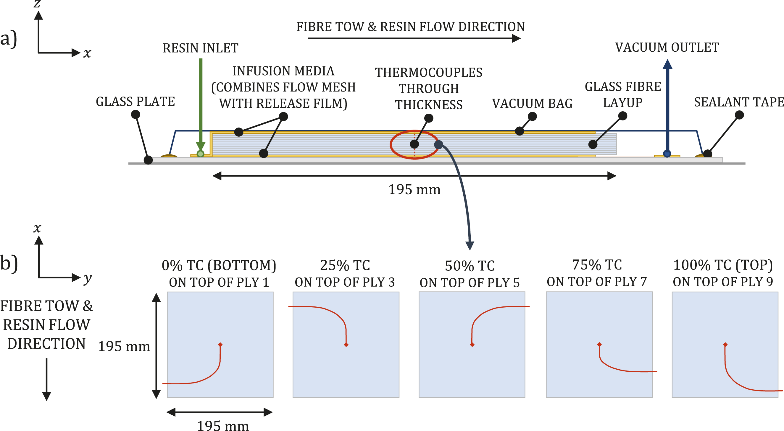
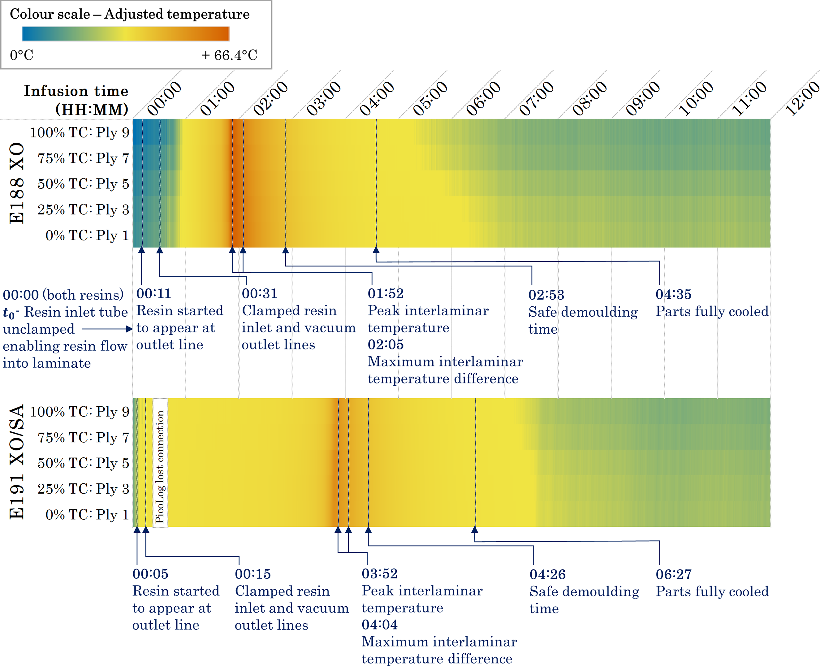
The seven Type K thermocouples were connected to a PicoLog TC-08 Data Logger, which sampled data at 1 Hz with a tolerance of ± 2.5°C. For each minute of recorded data, the minimum, maximum, and average temperatures were computed, with the average values for each minute subsequently used in all analyses. The data sampling covered 12 hours, with the start time, t0, corresponding to the point at which the resin inlet tube was unclamped, allowing resin to flow. For both laminates, t0 occurred no more than 10 minutes after the resin and initiator were combined, including the five-minute mixing period.
Infusion Setup
For the vacuum infusion, a glass plate, covered in release film, was used as the tool as shown in Figure 1(a). An infusion medium, combining the functions of flow mesh and perforated release film, was placed on top of the tool before the glass fibre fabric and thermocouples were laid up. The laminate consisted of 10 plies, each measuring 195 mm by 195 mm. The plies were placed to enable resin flow along the fibre tows (along the x axis). Another layer of infusion medium was placed on top of the stack. While flow mesh on top of a layup is standard practice, the additional layer placed under the glass fibre layup was used to encourage resin flow through the thick laminate. Sealant tape was applied around the edges of the tool. When laying the thermocouples, the section of wire closest to the sensor was placed in line with the 0° glass fibres before being routed across to the edge of the laminate, as shown in Figure 1(b). This was to ensure resin flow around the sensor, minimise the risk of air gaps, and replicate a non-instrumented vacuum infusion as closely as possible. To further reduce the chance of air gaps in the laminate as a result of the wires, the five thermocouples were arranged radially as opposed to being stacked. Each thermocouple cable had a diameter of 1 mm and comprised two twisted wires. At the point where the thermocouples passed through the vacuum bag and tool, the individual wires were separated and sealed to the tool using sealant tape. This removed the air gap between the two wires and reduced the local cross-sectional area at the seal, thereby minimising the potential for air leakage, demonstrated in Figure 2(b). (a) Experimental room-temperature vacuum infusion setup showing the insulated edges of the 10-ply glass fibre laminate. Acrylic-based liquid thermoplastic resins were used. (b) Thermocouple wires were separated where they passed through the seal. (c) Demoulded 9.5 mm-thick E188 XO and 10.1 mm-thick E191 XO/SA laminates after in situ polymerisation at room temperature.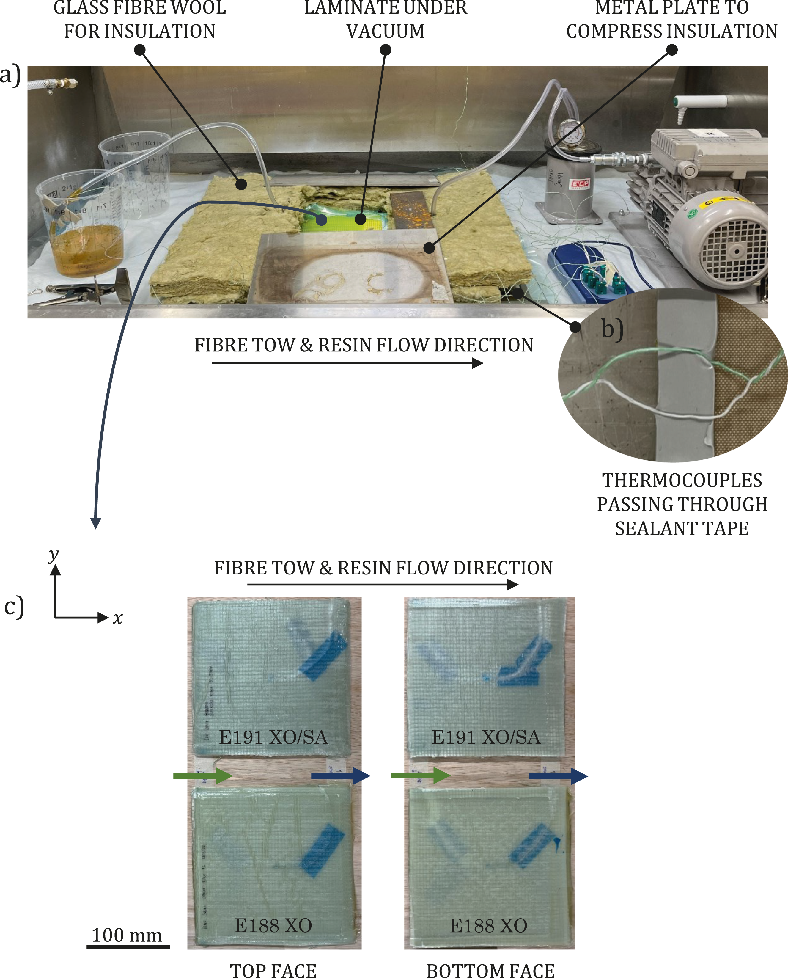
The entire laminate manufacturing process was conducted under a fume hood lined with a layer of breather fabric, where the top face of the infusion setup was left exposed. Following assembly, a ten-minute vacuum drop test was performed to assess the integrity of the vacuum. For each infusion, a leak rate below 3 mbar min−1 was confirmed.
The experimental laminates used in this study significantly smaller in length (x) and width (y) compared to a tidal turbine blade. To simulate a one-dimensional heat transfer scenario as much as possible and allow the effect of thickness on the infusion to be evaluated, the edges of each laminate were insulated using glass fibre wool compressed using metal plates, visible in Figure 2(a). It is therefore assumed that the four sides of the laminates were insulated during the infusion process but not the top or bottom faces, and that only the top face was exposed to air. The 9.5 mm-thick E188 XO and 10.1 mm-thick E191 XO/SA laminates are shown in Figure 2(c).
Nuclear Magnetic Resonance (NMR) Spectroscopy
To investigate any differences in monomer conversion between matrices, glass-fibre reinforced samples of each resin were analysed by NMR spectroscopy. 10 mm3 fibre-reinforced samples were immersed in chloroform (CDCl3) to dissolve the resin and the glass fibres were removed by filtration. The dissolved polymer samples were directly analysed as a CDCl3 solution, to avoid monomer loss during solvent evaporation. 1D NMR (1H) spectra were recorded on Bruker AVA500 and AVA600 spectrometers at 300 K operating at 500 MHz and 600 MHz, respectively. 1H spectra were referenced with respect to the residual peaks of deuterated solvents (CDCl3: 7.26 ppm).
Results & Discussion
Maximum Temperatures and Exothermic Reaction Onset
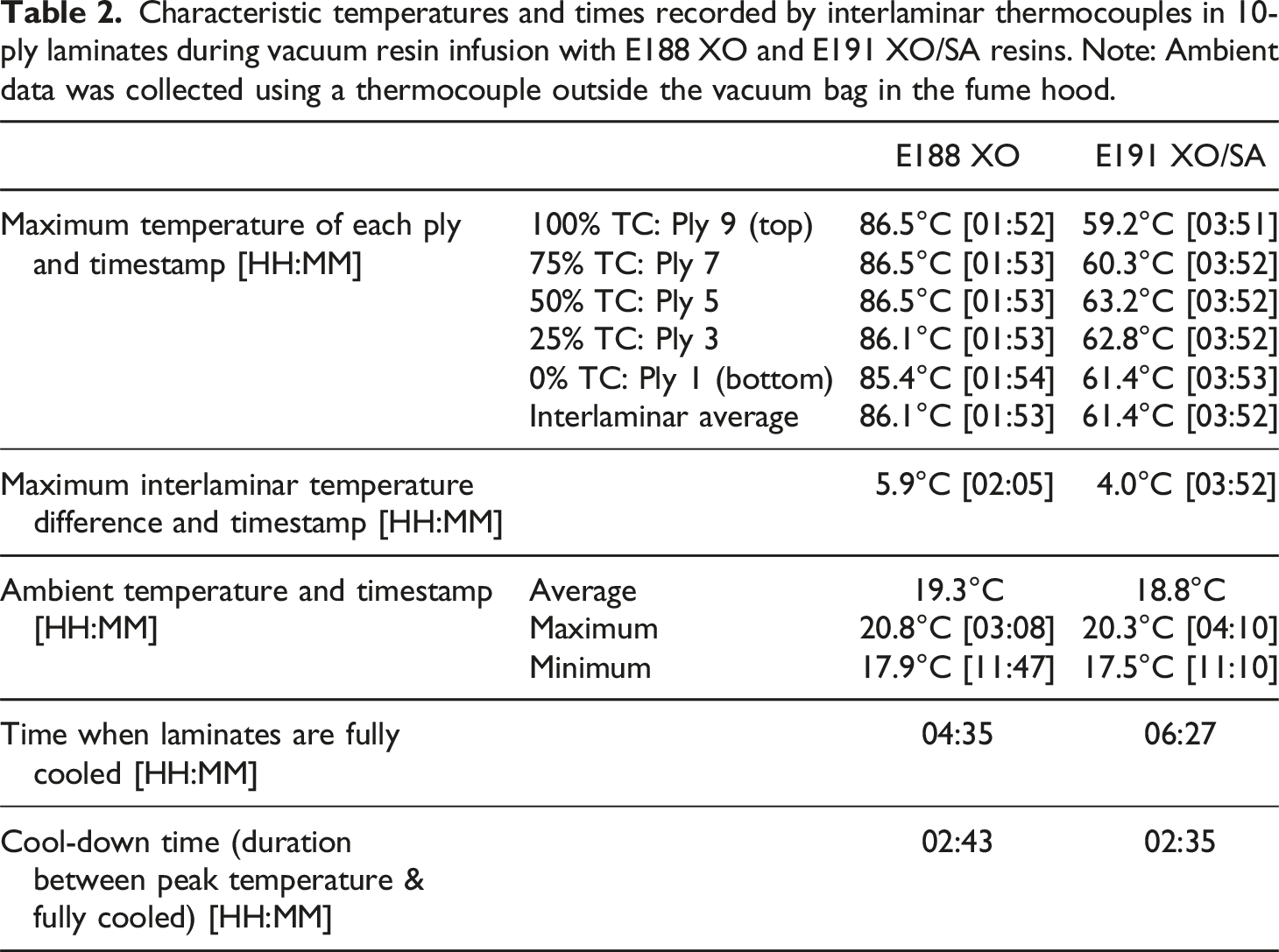
Figures 3 and 4 show the exothermic polymerisation profiles of the E188 XO and E191 XO/SA laminates, respectively, with temperatures measured at the locations shown in Figure 1(b), and the ambient temperature measured in the fume hood. For both laminates, the inlet gate was opened at t0, allowing resin to flow into the laminate. Since the thermocouples were positioned at the centre point of the laminate, there was a slight delay before the resin came into contact with the sensors. Data is shown for 12 hours of processing time, encompassing fill, polymerisation and cool-down times. This study defines a part as fully cooled when the temperatures of all plies are within 2.5°C of ambient air temperature; the cool-down time is considered as the duration between the peak temperature and when the part has fully cooled. Primary results are presented in Table 2. Exothermic polymerisation profile of E188 XO (10-ply, 9.5 mm-thick) laminate. Data was sampled over 12 hours, covering vacuum infusion and in situ polymerisation at room temperature. Exothermic polymerisation profile of E191 XO/SA (10-ply, 10.1 mm-thick) laminate. Data was sampled over 12 hours, covering vacuum infusion and in situ polymerisation at room temperature. The gap in data between 00:23 and 00:40 (HH:MM) is due to a loss of connection with the data logger. Characteristic temperatures and times recorded by interlaminar thermocouples in 10-ply laminates during vacuum resin infusion with E188 XO and E191 XO/SA resins. Note: Ambient data was collected using a thermocouple outside the vacuum bag in the fume hood.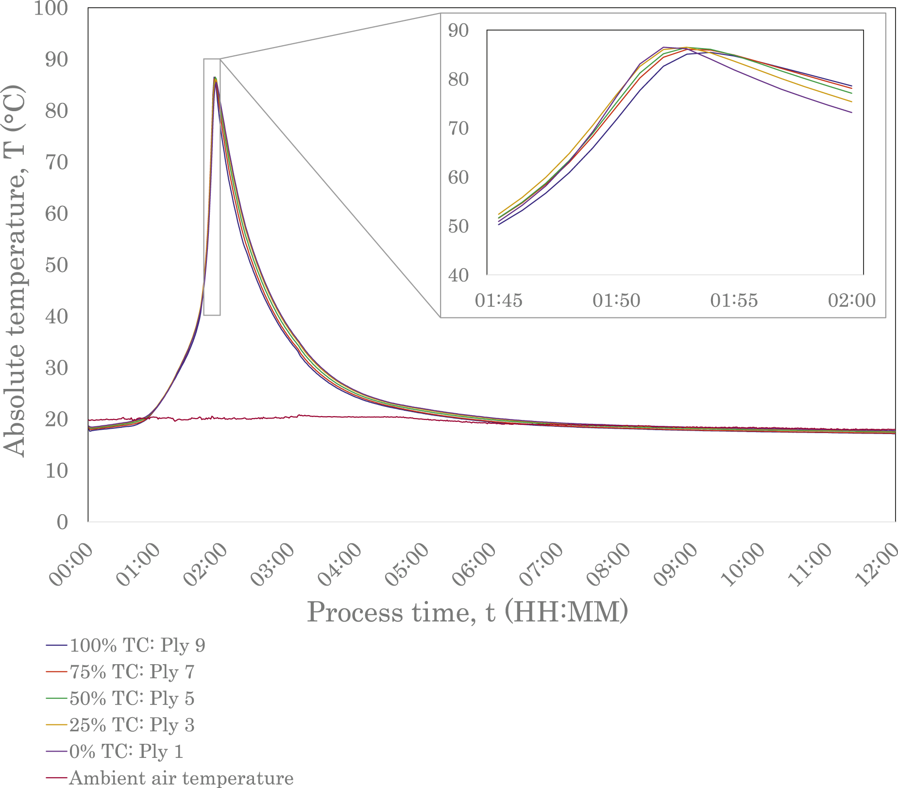
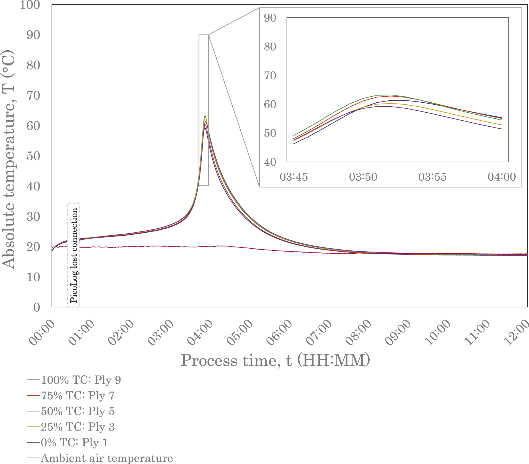
Through differential scanning calorimetry (DSC) experiments, multiple studies have investigated the heat flow behaviour of acrylic resins at different temperatures. It has been demonstrated that resins undergo an induction period before the polymerisation rate slightly decreases to a minimum value, based on free radical polymerisation theory. After the minimum value has been reached, the polymerisation rate is seen to increase to a peak before decreasing to a plateau, where the material has polymerised.32,33,39 The increased viscosity of the mixture during the propagation reaction reduces the diffusion rate of the chain radicals, lowering the termination reaction rate, and thereby increasing the polymerisation rate. If uncontrolled, the significant heat transfer can cause thermal runaway and depolymerisation.33,39,49 The auto-acceleration phenomenon, which drives the exothermic reaction in the polymerisation process, is known as the Trommsdorff or Gel Effect and is evident in the thermal profiles of the E188 XO and E191 XO/SA laminates, shown in Figures 3 and 4. Both graphs exhibit an induction period before the temperatures of all interlaminar thermocouples steeply increase. The longer reactivity specified by Arkema for E191 XO/SA is immediately obvious when comparing the two exothermic polymerisation profiles. The E191 XO/SA laminate, Figure 4, shows a slight increase in temperature almost immediately, indicated by the concave curve in the first 20 minutes of data collection. The interlaminar temperatures gradually increase for a significantly longer period compared to E188 XO before reaching a peak. This later onset time has a direct influence on the time when the laminates are fully cooled and, therefore, the overall process time, as demonstrated in Table 2.
The maximum temperatures were found to be 86.5°C and 63.2°C for the E188 XO and E191 XO/SA laminates, respectively, remaining below the boiling point of the resin (approximately 100°C) and, therefore, minimising the risk of voids and defects. Experiments conducted by Han et al. determined maximum temperatures as 62.5°C and 70°C, respectively, for 7.5 mm and 11.3 mm laminates manufactured from E150 with no exothermic control agent. 32 The overall behaviour of the E188 XO and E191 XO/SA laminates and shapes of their exothermic polymerisation profiles align with those of the E150 laminate thermocouple trials conducted by Han et al. 32
Although the maximum temperature determined by Han et al. for E150 with no exothermic control agent is similar to that of the E191 XO/SA laminate in this study, the exothermic reaction onset occurred much earlier in the infusion process. 32 This indicates a higher reactivity compared to both low-exotherm resin grades used in this study, ultimately leading to a shorter process time. The onset and peak temperatures of the exothermic reaction exhibited by these LTPRs are affected by multiple factors, including type of monomer, the type and concentration of initiator, and process temperature. Multiple studies have shown that process temperature has a significant effect and Han et al. demonstrated that the exothermic reaction onset could be brought forward for acrylic LTPRs by increasing temperature.32,35,49,50 The ability to manipulate this reaction onset to suit cycle times could be beneficial in manufacturing settings depending on setup. If, however, temperature control of resin is not feasible when working at ambient temperature, perhaps due to reasons of scale or other practicalities, results from this study reinforce that different resins could be considered with different onset times. It is worth noting that although a delayed exothermic reaction onset will result in a longer process time, there may be instances where a longer induction period is desirable. This would allow more time for the resin to infuse before undergoing the polymerisation reaction and could have benefits if infusing a longer part using a gate strategy, for example.
Offset Adjustment of Interlaminar Temperatures Against Ambient
Figure 5 enables a more direct comparison between the two infusions. All interlaminar temperature readings have been adjusted against ambient air temperature for each minute using Equation (1). Figure 5 reinforces that the maximum temperature of E188 XO is significantly higher (23.3°C) than that of E191 XO/SA. The delayed reactivity, and, therefore, longer process time of E191 XO/SA is also apparent. The maximum rate of change of temperature for the two laminates was found to be 7.1°C/minute and 2.9°C/minute occurring at 01:50 and 03:48 for the E188 XO and E191 XO/SA laminates, respectively. Both of these instances occur within 5 minutes of the peak interlaminar temperatures, demonstrating the rapid exothermic reaction that occurs in these acrylic-based LTPRs. Interlaminar exothermic polymerisation profiles versus time for two different liquid thermoplastic resins (E188 XO and E191 XO/SA). Temperatures were adjusted against ambient temperature for each minute. Note: infusion and polymerisation processes were carried out at room temperature; temperature changes occur as a result of exothermic polymerisation changes.
Thermal Gradient through Laminate Thickness
Table 2 highlights the greater variation in peak temperatures of plies in E191 XO/SA compared with that of E188 XO. From Figures 3 and 4, it appears that, within 10 minutes of peaking in temperature, the highest temperatures were at the bottom of the laminate with temperatures gradually decreasing to a minimum at the top of the laminate for the duration of the cool-down period for both material systems. This trend is also evident in Figure 5. Although the base of the laminate was not insulated, the glass manufacturing plate and the fume hood base could have acted as insulators in comparison to the exposed top surface, explaining this behaviour.
Unwanted residual stresses can occur in a laminate if there are significant temperature differences between plies during manufacture.19,31,51 Maximum temperature differences reported by Han et al. were 8°C and 10°C for 7.5 mm and 11.3 mm laminates, respectively. 32 In this present study, where thicknesses are nominally 10 mm, the maximum temperature differences were 5.9°C for the E188 XO laminate and 4.0°C for the E191 XO/SA. This suggests that a low-exotherm grade of LTPR results in a lower thermal gradient across the laminate, reducing internal stresses and the likelihood of shape distortions. Further work investigating the impacts of thickness on the maximum temperature differences between plies would enable a more accurate analysis of the behaviour of thermoplastic resins.
Nuclear Magnetic Resonance (NMR) Spectroscopy
To examine whether any monomer remained present, the NMR spectrum of each polymer matrix was measured and compared to those of the starting materials that is, virgin Elium® resin and initiator as separate components. Obande et al. previously reported NMR spectra with the residual monomer and polymer signals for E180. 52 For both E188 XO and E191 XO/SA, it was apparent that traces of monomer remained in the sample. The calculated monomer conversions for both polymer samples based on the 1H NMR spectra were found to be 99% and 98% for the E188 XO and E191 XO/SA fibre-reinforced samples, respectively. These values were determined by comparing the relevant integrals for the monomer and polymer peaks. It is important to note that this method of determining conversion assumes no monomer is lost during or after the polymerisation. This is because polymer samples were directly dissolved in the analysis solvent (CDCl3) to ensure minimal monomer loss. These high degrees of conversion are indicative of highly effective polymerisation processes for both resin systems, suggesting that the auto-acceleration phenomenon did not prevent or significantly inhibit polymerisation overall. The 1H NMR data shows that even though the polymerisation is slower with E191 XO/SA, both polymerisations eventually reach very high monomer conversions.
Demoulding and Potential Implications for Industrial Manufacturing
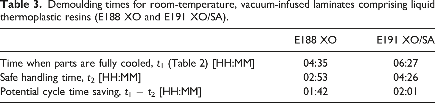
Demoulding times for room-temperature, vacuum-infused laminates comprising liquid thermoplastic resins (E188 XO and E191 XO/SA).
For improved manufacturing development and quality control, thermocouples could be strategically placed between the tool and the laminate as well as on top of the laminate. By monitoring the temperatures at these locations, operators could detect the exothermic reaction peak, a key indicator of the progression of the reaction and therefore manufacturing process. In the absence of an embedded thermocouple, which would compromise quality in industrial settings, temperature readings from these thermocouples would reveal characteristic trends and give an indication of temperatures reached. Awareness of the proximity to the critical boiling point, or instances of large thermal gradients, would provide insights into the quality and properties of the finished parts. Operators could also confirm when the parts had sufficiently cooled and were safe for handling and demoulding. Additional thermocouples could be utilised to monitor the temperature of the resin source and ambient air temperature during manufacture to manage the risk of thermal runaway, which has safety benefits as well as preventing waste of materials.
It is expected that as more experimental data for LTPR manufacturing is generated, validated predictive models for thermal behaviour and resulting residual stresses will enhance understanding and manufacturers’ ability for optimisation.32,58–64
Conclusions
This paper reports novel insights into the exothermic polymerisation behaviour and captures industry-relevant findings for the production of recyclable tidal turbine blades. The exothermic polymerisation profiles of two liquid thermoplastic resins, E188 XO and E191 XO/SA, were experimentally evaluated, addressing key knowledge gaps in the use of low-exotherm liquid thermoplastic resins for thick-section laminate manufacturing. The temperature evolution of two 10-ply laminates was monitored by recording temperatures over a 12-hour period using five embedded thermocouples positioned at regular interlaminar intervals. The polymerised thicknesses of the E188 XO and E191 XO/SA laminates were 9.5 mm and 10.1 mm, respectively. E188 XO exhibited a higher exothermic peak temperature (86.5°C) compared with that of E191 XO/SA (63.2°C). The E188 XO laminate was found to exhibit a higher thermal gradient between plies (5.9°C) versus E191 XO/SA (4.0°C). However, the later onset of the exothermic reaction in E191 XO/SA led to a longer process time.
Monitoring the temperature of laminates during manufacture will provide valuable insights into the through-thickness thermal profile, thereby improving understanding of the resulting properties of parts. Additionally, these temperature readings could be used to inform demoulding times with the potential for process-time savings, given the high variability reported in the literature. Nonetheless, manufacturers will likely explore the most influential process parameters in line with their specific needs when specifying materials.
Further work should investigate the thickness effects on exothermic polymerisation profiles during vacuum infusion manufacture of thick-section laminates, working towards greater thicknesses. The experimental data from all trials will serve as the basis for future work focused on validating numerical models.
From this study, the peak temperatures, thermal gradient between plies, and manufacturing process times suggest that both grades of Elium® may be readily considered alongside traditional thermosetting resins during material selection in the manufacture of tidal turbine blades.
Footnotes
Acknowledgements
The authors would like to thank Arkema GRL, France; Professor Dipa Roy and Johns Manville for providing material samples used in this research.
Author contributions
Ione L. M. Smith: Conceptualisation, methodology, project administration, resources, investigation, formal analysis, visualisation, writing - original draft preparation, writing - review and editing. Anna Lykkeberg: Investigation, formal analysis, writing - original draft preparation, writing - review and editing. Jennifer A. Garden: Investigation, formal analysis, writing - original draft preparation, writing - review and editing. Edward D. McCarthy: Supervision, writing - review and editing. Philipp R. Thies: Supervision, writing - review and editing. Selda Oterkus: Supervision, writing - review and editing. Winifred Obande: Conceptualisation, supervision, resources, project administration, writing - original draft preparation, writing - review and editing.
Declaration of conflicting interests
The author(s) declared no potential conflicts of interest with respect to the research, authorship, and/or publication of this article.
Funding
The author(s) disclosed receipt of the following financial support for the research, authorship, and/or publication of this article: The authors are grateful to EPSRC and NERC for funding for the Industrial CDT for Offshore Renewable Energy (EP/S023933/1) [I.L.M.S.]; financial support from the School of Engineering, University of Edinburgh through an Elizabeth Georgeson Fellowship [W.O.]; EPSRC SOFI2 Centre for Doctoral Training and Croda (EP/S023631/1) [A.L.]; UKRI Future Leaders Fellowship (MR∖T042710∖1) [J.A.G.].
Data Availability Statement
Data will be made available on request.