
Abstract
Rotor blades are critical components of tidal energy converters, typically manufactured from thermoset fibre-reinforced composite (FRC) materials using vacuum infusion processing. High load demands result in thick-section laminates (10–100 mm), particularly at the blade root, posing manufacturing challenges. While tidal and wind turbine blades appear similar in design, the fundamentally different operational conditions result in distinct structural differences and, therefore, manufacturing requirements, offering opportunities for the tidal sector to innovate. Advances in materials and manufacturing technologies provide potential to rethink current practices for improved design and process efficiency. Additionally, the relative immaturity of tidal technology allows for early integration of circularity principles, minimising waste and optimising resources. This paper serves as a comprehensive resource for the tidal turbine blade sector, reviewing current manufacturing practices and exploring alternative techniques. Combining knowledge from academic literature and industrial reports, it outlines blade design, material selection, and current manufacturing processes. The paper evaluates emerging techniques and potential modifications to established methods. Due to the range of turbine designs in the sector, optimal materials and manufacturing combinations will differ. This study offers manufacturers valuable insights to support informed and strategic choices to improve and advance tidal turbine blade production.
Keywords
Introduction
Tidal energy holds significant potential as a reliable renewable energy source. The practical resource in the UK and British Channel Islands is estimated at 34 TWh/year, equal to around 11.5 GW of installed capacity.1,2 While technology across the sector varies, rotor blades are essential to most tidal stream energy converters. In addition to being continuously submerged in saltwater, tidal turbine blades endure high cyclic loads, requiring the use of thick-section laminates (10–100 mm), especially in the root.3,4
Tidal turbine blades are widely manufactured from fibre-reinforced epoxy thermoset composite materials using vacuum infusion processing.3–7 Sustainability concerns around thermoset materials have driven the development of alternative resins such as liquid thermoplastic and recyclable thermoset resins.7–9 Although many of these resins have been designed as direct replacements in current manufacturing methods, the use of alternative resins provides the opportunity to utilise different manufacturing methods. Considering material selection and manufacturing processes together as opposed to two separate entities is essential in enabling more efficient engineering and cost-efficient production.
The literature on blade manufacture primarily focuses on wind turbine blades or improvements to conventional manufacturing processes. However, the distinct operational conditions of tidal turbines subject blades to significantly higher loads, meaning that wind turbine blade designs cannot be directly transferred, thus limiting the applicability of current approaches. For blades of equivalent length, these higher loads necessitate different design principles and material selection strategies for tidal turbine blades compared to wind turbine blades. In parallel, the need to reduce the relatively high Levelised Cost of Energy (LCOE) of tidal energy calls for more efficient designs, reduced material usage and costs, and improved processing efficiency. As large-scale, well-established blade manufacturers remain focused on the wind energy sector, there is an opportunity and need for small-to-medium-sized enterprises (SMEs) to contribute to the development of tidal blade technology. As these firms enter an unfamiliar and emerging market, access to consolidated and reliable technical information becomes essential.
Therefore, the aim of this paper is to provide a comprehensive resource for manufacturers in the tidal turbine sector, both established and new entrants, reviewing current blade manufacturing practices and exploring the applicability of alternative techniques and materials. Drawing on academic literature and industry reports, while acknowledging that much proprietary information remains within the private commercial domain, this paper outlines current blade design considerations and material selection strategies. It reviews existing manufacturing and assembly processes, then examines emerging technologies and potential adaptations to established composite manufacturing methods. The study evaluates the potential for these alternatives to advance the commercial manufacture of tidal turbine blades, offering practical insights aimed at improving manufacturing efficiency and reducing costs.
Tidal energy converters
Energy can be harnessed from tides using tidal range or tidal stream converters. Tidal range systems typically take the form of tidal barrages, dam-like structures with turbines at their base that capture the energy from the changing water level of the tides. Tidal stream technology exploits energy from the horizontal movement of tidal currents, driven by the ebb and flow of the sea, and is considered in this paper.10–12 The sector has seen a diverse range of technologies developed, tested, and deployed around the world, demonstrated by Figure 1. Most tidal stream devices are horizontal axis turbines, which may be mounted on floating structures with the turbines operating near the top of the water column, or on fixed platforms located on the seabed.13,14 While some developers have deployed fewer, larger devices, and others have implemented a greater number of smaller turbines, tidal turbine blades remain crucial components in most designs, as demonstrated in Figure 2.
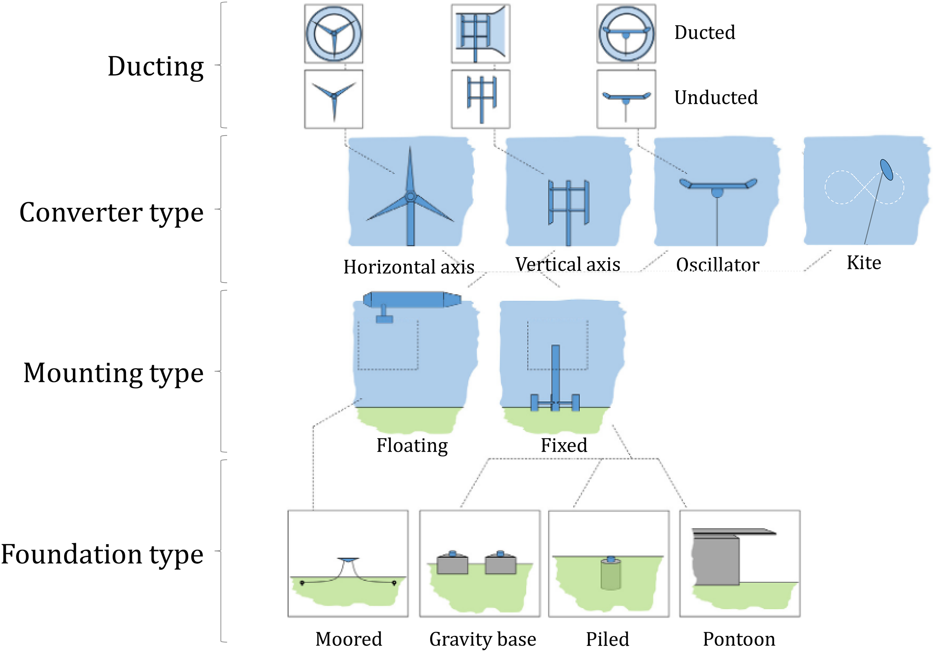
A summary of tidal energy converter devices. Adapted from Walker and Thies. 11
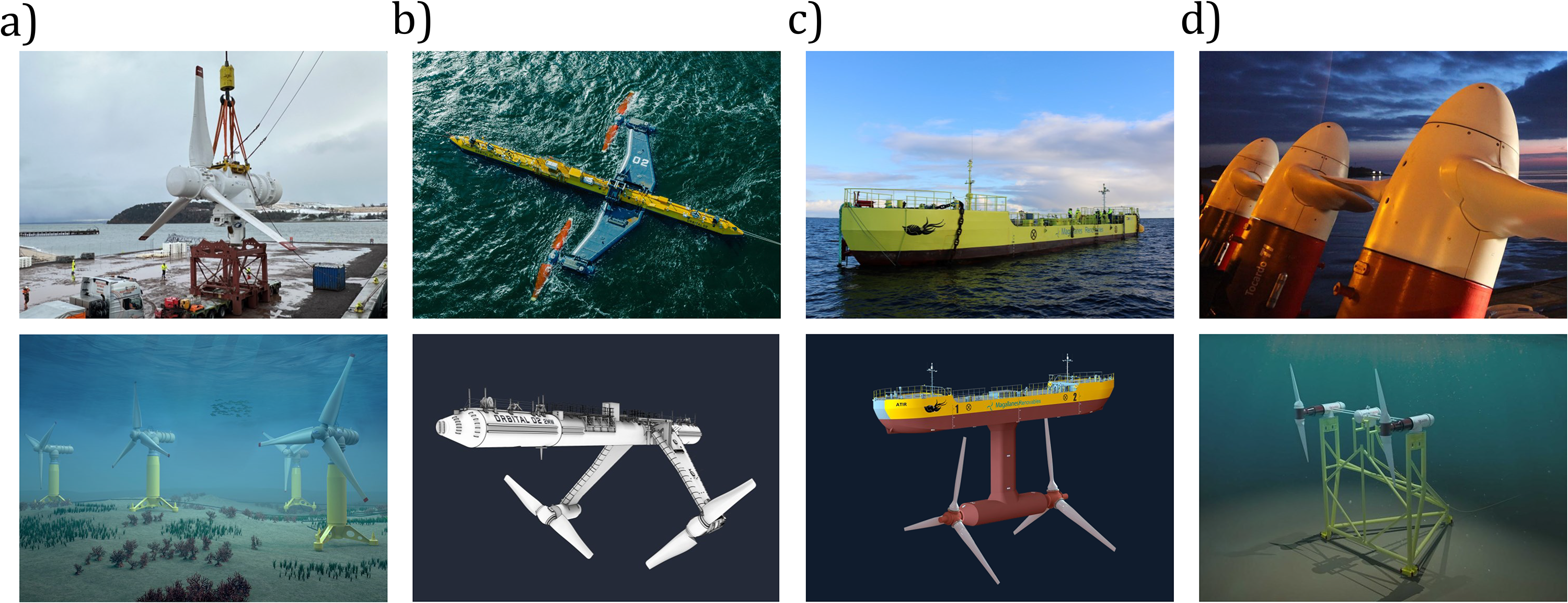
Tidal turbine devices deployed or scheduled for deployment in the UK by various developers. a) MeyGen - Proteus Marine Renewables, b) Orbital Marine Power, c) Magallanes Renovables, d) HydroWing - QED Naval - Tocardo.
Blade design
Although tidal and wind turbine blades may appear similar in overall form, their design requirements diverge significantly due to the distinct operational environments in which they function. The greater density of water compared to air allows tidal turbines to generate more power than wind turbines with similar blade dimensions.17,18 Tidal turbine blades are typically 2 m to 10 m in length, whereas the longest manufactured wind turbine blade is currently 131 m.19–24 Within the tidal energy sector blade design varies depending on factors such as rated power and therefore size, position in the water column and site specific conditions. Both wind and tidal turbine blades begin with a circular root and transition into an aerofoil profile that tapers along the length, as illustrated in Figure 3.3,17,25,26 Due to the shorter overall length of tidal turbine blades, this transition in cross-sectional profile occurs over a smaller distance. This results in rapid changes in stresses, requiring the redistribution of load away from the root into structural elements such as shear webs and spar caps.3,17,25,26 Operating in turbulent marine environments with high flow speeds, tidal turbine blades experience spatially and temporally varying loadings driven by the combined effects of shear, turbulence, and wave-induced velocities.17,18,27–30 These high loads necessitate balancing the pressure difference between the blade’s exterior and interior, which is sometimes achieved by filling the cavity with foam. Additionally, the continuous exposure of the blade skin to saltwater poses risks of material degradation and water absorption, which can compromise the blade’s mechanical properties over time.3,17,25,26,30,31 Priorities in design therefore differ between tidal and wind turbine blades. Whilst minimising weight is highly important for wind turbine blades, for instance, strength and fatigue resistance are arguably more critical in tidal turbine blades.
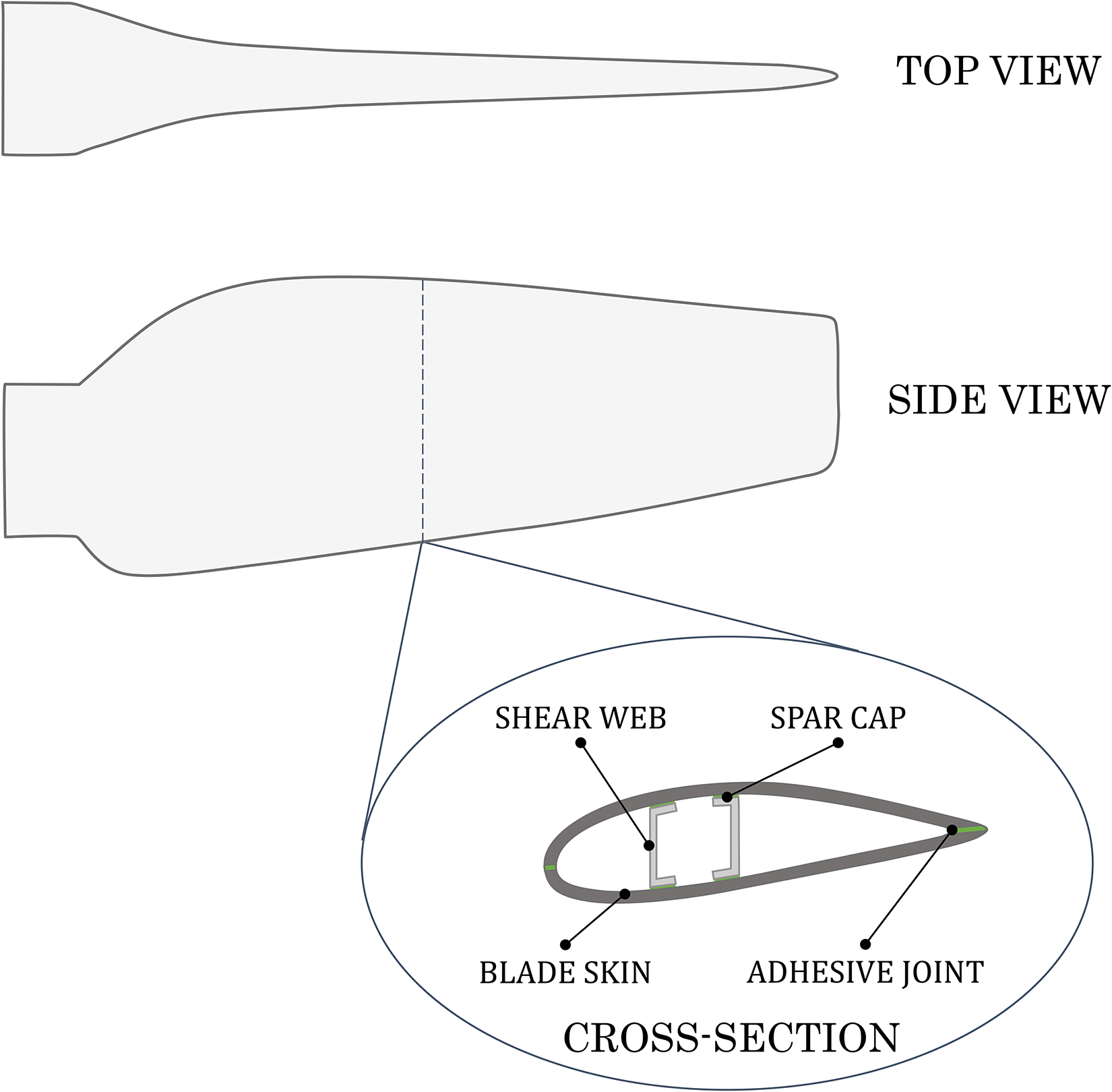
General design of a tidal turbine blade.
To address these challenges and minimise the risks of intervention in difficult operating conditions, tidal turbine blades are designed with thick laminate sections to enhance structural resilience, Figure 3. Definitions of what constitutes a thick-section laminate vary in the literature, with reported thicknesses ranging from 10 mm to 100 mm. These values typically depend on the position along the blade, with the root exhibiting the greatest skin thickness due to the combined effects of blade weight, hydrodynamic loading, and resulting bending moments.3,4 Factors such as site specific operating conditions and design parameters, including overall size, geometry, and reinforcement strategy, have direct influence. Material selection also has a significant impact, e.g., a glass fibre-reinforced composite part will need to be thicker to achieve the same strength properties as its carbon fibre-reinforced counterpart.4,18,32–34
Material selection
Fibre-reinforced composites (FRCs) are generally used in tidal turbine blades due to their high specific strength and stiffness and corrosion resistance, where a resin matrix is reinforced with fibres. While carbon fibres (CFs) offer higher strength than glass fibres (GFs), their higher costs renders the resulting composite parts more expensive. The selection of CFs or GFs is, therefore, driven by performance requirements, design and economics and a combination of the materials is sometimes used. Fibres are combined with a thermoset-matrix polymer resin, generally epoxy, to form a FRC. Glass fibre-reinforced polymers (GFRPs) are commonly used for the skin of the blade as they are a more cost-effective option for a large surface area, while carbon fibre-reinforced polymers (CFRPs) are used for high-strength or high-stiffness components such as the root or spar.17,25,27
Thermosets have traditionally been the preferred matrices for composite applications because of their excellent manufacturability, good mechanical properties, environmental resistance, and low cost. The cross-links in thermosets provide the durability and structural resilience required for tidal turbine blade components. However, these same bonds typically prevent melting and reshaping, which are essential characteristics for many conventional recycling processes that are applicable to thermoplastics. Although several solutions are under development, there are currently no large-scale recycling technologies for managing decommissioned turbine blades, so blades are incinerated or disposed of in landfill if they are not repurposed. At present, the waste generated by the tidal energy industry is relatively low due to the limited number of deployed devices, most of which are yet to reach their end-of-service-life (EOSL). Nevertheless, it is estimated that 1 GW of tidal energy capacity will result in around 6,000 tonnes of blade waste. Predictions indicate that the UK will have 0.9 GW of installed tidal capacity by 2035, highlighting the significant potential for waste generation.14,35
Although turbine-blade recycling solutions are under development, many remain at a low technology readiness level (TRL), are expensive, or impose other detrimental environmental impacts.7,9 As this rapidly expanding field lies beyond the scope of the present paper, this section instead provides an overview of inherently recyclable resin materials suitable for tidal turbine-blade manufacture. The ability of thermoplastics to be melted and reformed offers the opportunity to recycle parts at their EOSL. While thermoplastics offer superior toughness, impact resistance and favourable out-of-plane properties, they are generally solid at room temperature. The requirement for high temperatures and pressures to overcome their high melt viscosities during processing limits their applicability.36–39 Recent advances in recyclable liquid thermoplastic resins (LTPRs), such as Elium®, demonstrate strong potential to directly replace epoxy in current vacuum infusion manufacturing processes.5–8,26,40,41 These acrylic-based resins can be processed at ambient temperatures due to their low viscosity and undergo in-situ polymerisation without the need for external heat input. Resulting parts typically exhibit high strength, toughness, impact resistance and ductile failure behaviour.36,40,42–45 LM Wind Power, a subsidiary of GE Renewable Energy Business, produced a wind turbine blade from Elium® as part of the ZEBRA (Zero wastE Blade ReseArch) project. They are now planning to conduct structural lifetime testing and assessment of recycling methods.46–48 Meanwhile, National Renewable Energy Laboratory (NREL) produced tidal turbine blades using Elium®, measuring 2.5 m in length, which were deployed in Verdant Power’s test site in New York’s East River for six months.26,49,50 The testing showed incompatibilities of the LTPR with epoxy foam currently used in epoxy blades. Although initial tests indicated that epoxy paints were suitable for use, areas on the blade that were missing paint were noted at the end of submersion testing. The blades also exhibited adhesive failure along the leading edge, initiated between the FRC skin and the epoxy foam in the cavity. The research highlights the importance of further development to ensure the compatibility of these resins with foams, adhesives, and overlay resins, which might be used in production. 26
Significant progress is being made in the development of recyclable thermosets comprising degradable or dynamic covalent bonds that are recycled using thermal techniques or chemical factors such as solvents.7,9 Commercial recyclable epoxy-based materials include Recyclamine® (Aditya Birla51–53), EzCiclo (Swancor54–56), Vitrimax (Mallinda 57 ), and the Reprocessable, Repairable, and Recyclable (3R) resin system (CIDETEC58–60). 9 These systems are designed to work with existing manufacturing processes and are offered in either prepreg or liquid resin formats, depending on the specific product. In 2020, Siemens Gamesa produced RecyclableBlade wind turbine blades using Recyclamine. These blades were installed by REW in the Kaskai Offshore Wind farm in 2022 and later in the Sofia Offshore Wind Farm, Dogger Bank.9,61–64 MingYang Smart Energy used EzCiclo to develop wind turbine blades.9,65 Swancor, the producers of EzCiclo, signed a letter of intent with Siemens, and from 2026, all resin supplied to Siemens will be recyclable, contributing to RecylableBlade and increasing Siemens’ capacity.66,67 Additional environmental concerns regarding the energy-intensive processing of epoxy resins include the use of toxic compounds, high carbon dioxide emissions, and the reliance on finite petrochemical resources.68,69 These issues have prompted research into bio-based resins as alternatives.68–71 Although some projects are evaluating the suitability of bio-resins for blade manufacturing, they seem to have a lower TRL than those discussed previously.72–74 Although recent advances in recyclable thermosets focus on wind turbine blade production, they show great promise for the future of tidal turbine blade manufacturing.
Material selection and manufacturing methods interdependency
Depending on the manufacturing method employed, precursor materials can take various forms as shown in Figure 4. Innovations in alternative resins, composite reinforcement forms and novel manufacturing methods, have significantly expanded the range of manufacturing options. Integrating material selection with manufacturing processes and capabilities during development facilitates alternative and potentially more efficient structural design.

Process from constituent materials to finished part.
In the literature, manufacturing methods are commonly categorised by fibre length, reinforcement form, resin form or resin type (thermoset or thermoplastic). While these factors are connected, this review will classify materials based on their form at the point of infiltration. For the purpose of this review, the following material forms are the main classes considered, though the list is not exhaustive.
Figure 5 categorises composite manufacturing techniques and their use with different material system forms. Highlighted processes will be discussed in further detail in the following sections, and their suitability for the manufacture of tidal turbine blades will be assessed.
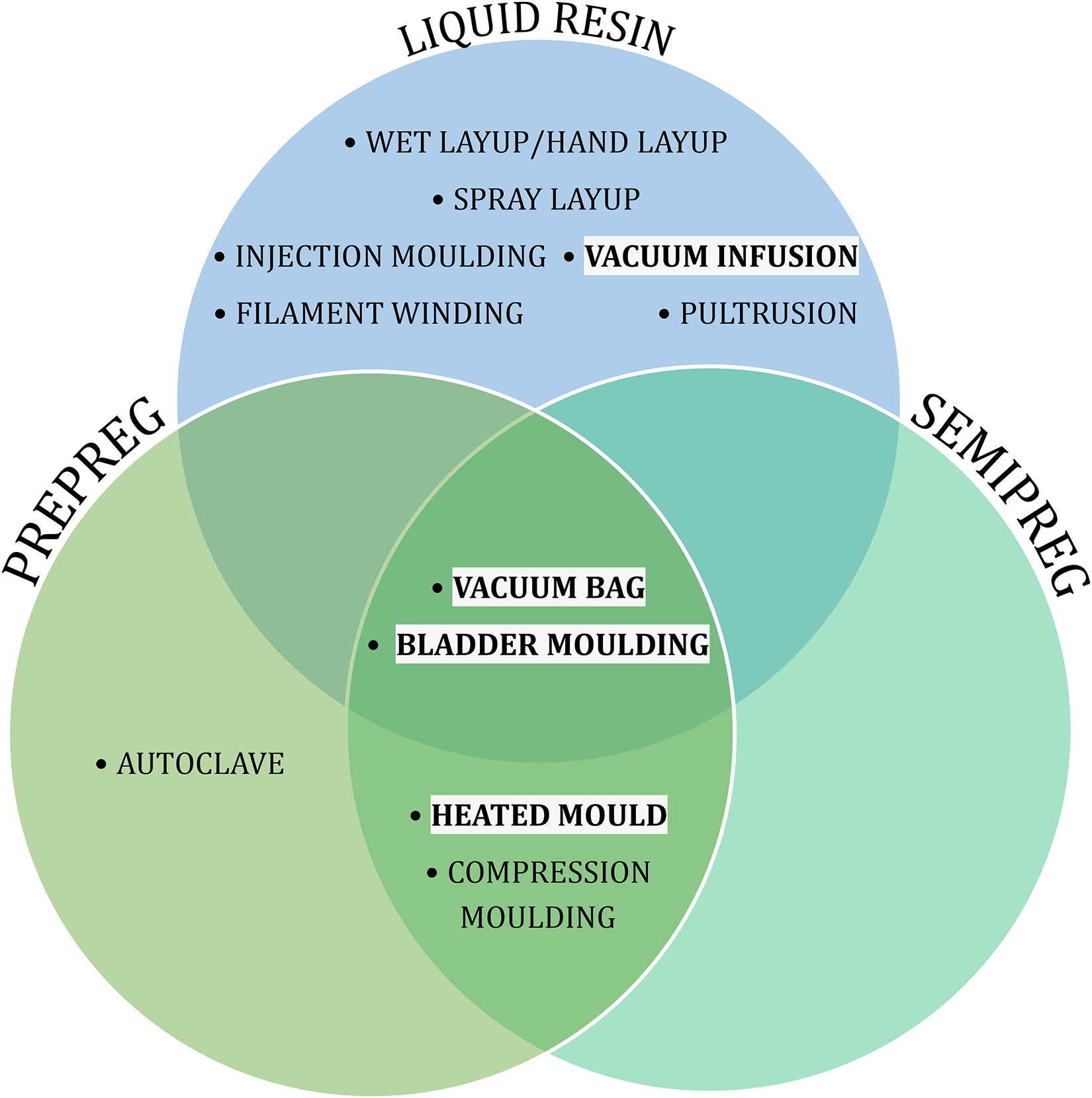
Composite manufacturing methods classified by material form at point of infiltration. Highlighted processes will be further reviewed in this study.
Current blade manufacturing and assembly
Tidal turbine blades are widely manufactured using vacuum infusion processing. Each blade is formed of two shells, which are individually produced using vacuum infusion before being joined together. To create each shell, a gel coat is first applied to a single-sided mould to protect the dry fibres. Fibres, in the form of mats or fabrics, are then placed into the mould. Root inserts and spar caps are positioned before laying additional dry fibres. Specific areas of the blade, such as the root, will typically be reinforced with more layers of fibre. Fibre orientations may be varied in certain regions of the blade to tailor mechanical properties. The fibres are then infused with resin, as described in the “Vacuum infusion” section, and later demoulded to leave a shell. Structural reinforcements, such as shear webs, are then attached, and the two shells joined together using structural adhesive. Joining and the potential to manufacture blades as a single piece is discussed in more detail in the “Removing the need for joining” section. Additional materials or overlay resins may be applied to the leading edge for additional protection. Finally, the entire blade is post-processed, applying coatings such as filler, primer and paint. In some cases, the blade is then filled with foam.4,8,26,35,75,76
Vacuum infusion
Vacuum infusion processing relies on the extraction of air to create a vacuum, which assists the continuous flow of low-pressure resin into dry fibres and consolidates the laminate. As outlined previously, dry fibres are placed into a mould and manufacturing aids are laid on top of the layup. These are generally single-use consumables. Resin inlet and vacuum outlet ports are carefully installed. An impervious layer of plastic film (vacuum bagging) is then draped over and sealed to the tool. The general layup sequence for vacuum infusion and the purpose of each consumable are summarised below.77–82
To infuse the part, a pot of resin is connected to an inlet port using a feed line, normally positioned at the opposite end of the layup to the vacuum outlet to ensure resin flow through the fibrous preform by the vacuum, as demonstrated in Figure 6. When the laminate is fully infused, the inlet and outlet tubes are clamped, maintaining the vacuum in the bag. The material is left to solidify, and a post-processing heat treatment may be applied to enhance properties, as required for certain thermoset-matrix materials.77–82
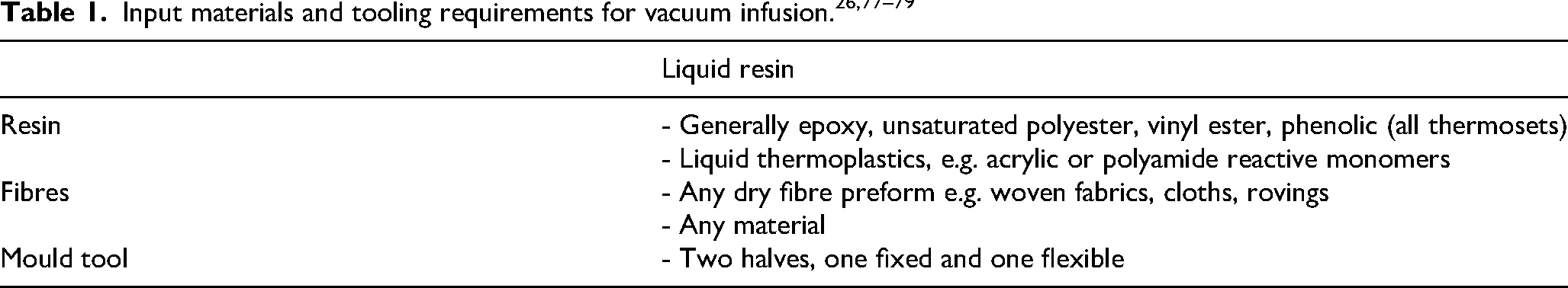
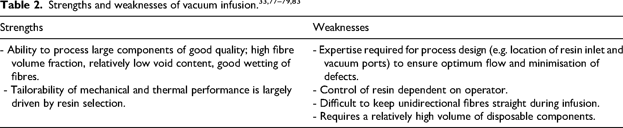
A summary of potential input materials for vacuum infusion is provided in Table 1. An evaluation of strengths and weaknesses associated with the process is provided in Table 2. Vacuum infusion is a well-established process and is commonly used in the manufacture of wind and tidal turbine blades, as well as small-scale production of small yachts. The process can be described using different names, and in the context of blade manufacture, is often referred to as Vacuum Assisted Resin Transfer Moulding (VARTM). There is a wide range of consumables and resin types available for different applications to ensure compatibility. Larger parts may require innovative gate strategies, where multiple resin inlets are used to control the flow front of the resin. The location of these points is largely dependent on the part geometry. Vacuum infusion process optimisation is a significant area of research and development with various operating parameters strongly related to the part shape and design. As such, process-specific expertise is required.
Manufacturing challenges
Thick-section laminates occur throughout tidal turbine blades, particularly at the root, as discussed in the “Blade design” section. Conventional composite manufacturing challenges, such as incomplete fibre wetting, insufficient ply consolidation and trapped air are intensified in thick-laminate sections. These issues can lead to the formation of voids, uneven material curing or polymerisation, and dimensional inconsistencies. For liquid resins, there is a risk of variation in resin flow across the part, while prepreg materials may require multiple debulking stages to eliminate trapped air.4,32,77,79 Managing heat effectively during the production of thick-section laminates is critical and complex. Significant heat generated by exothermic reactions can result in defects, shape distortions, and uneven residual stresses , which arise from temperature gradients between plies.4,79,84,85 This heat generation is due to the cross-linking during curing in thermosets and free radical polymerisation in monomeric thermoplastics.44,85–87 Thicker laminates make it more difficult for generated heat to dissipate, prompting the development of low-exotherm resins, some of which are targeted for wind and marine applications, where thick-section composites are frequently used.
Innovations such as Gurit’s SPRINT® address some of these challenges. These materials incorporate a pre-cast, pre-catalysed resin film positioned between layers of dry fibres that have not yet been impregnated with resin. As such, they are classified as a semipreg in this review. Designed for use like conventional prepregs, they require a vacuum bag and the application of heat to achieve the form of the final part. When a vacuum is applied, air is evacuated from the fibre bundles and between layers through the dry fibre network. Increasing the temperature allows the resin to soften and flow into the dry fibres. The resulting void content is very low – typically quoted between 0% and 0.5%.77,87,88
Without proper management of the manufacturing process, laminates may exhibit deformation, defects, and undesirable residual stresses, leading to reduced and variable mechanical properties through the thickness. To mitigate the risk of failure and compensate for uncertainties in material properties, conservatively high design factors are applied. While this approach enhances reliability, it also increases material usage and cost, and may exacerbate the aforementioned challenges.
Alternative manufacturing methods
Although vacuum infusion is widely used to manufacture wind and tidal turbine blades, new materials and the relative immaturity of the tidal sector provide the opportunity to re-evaluate current practices. The remainder of this study will discuss alternative manufacturing methods that could be used in the production of tidal turbine blades.
Vacuum bag and oven
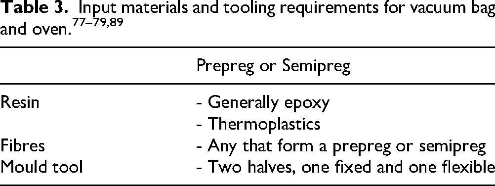
The vacuum bag process shares similarities with vacuum infusion but is used with prepreg or semipreg material forms, as outlined in Table 3. Figure 6 may be referenced for the general layout, with the following adaptations: the resin flow inlet is excluded, prepreg or semipreg plies are used instead of a dry fibre preform. Plies are assembled into the mould, with rollers used to eliminate air pockets between them. A layer of release film is typically applied before bagging the layup and drawing a vacuum. Prepreg and semipreg materials require the application of heat to soften the impregnated resin, enabling it to flow into the fibres. The entire setup can then be placed in an oven.77,78,89
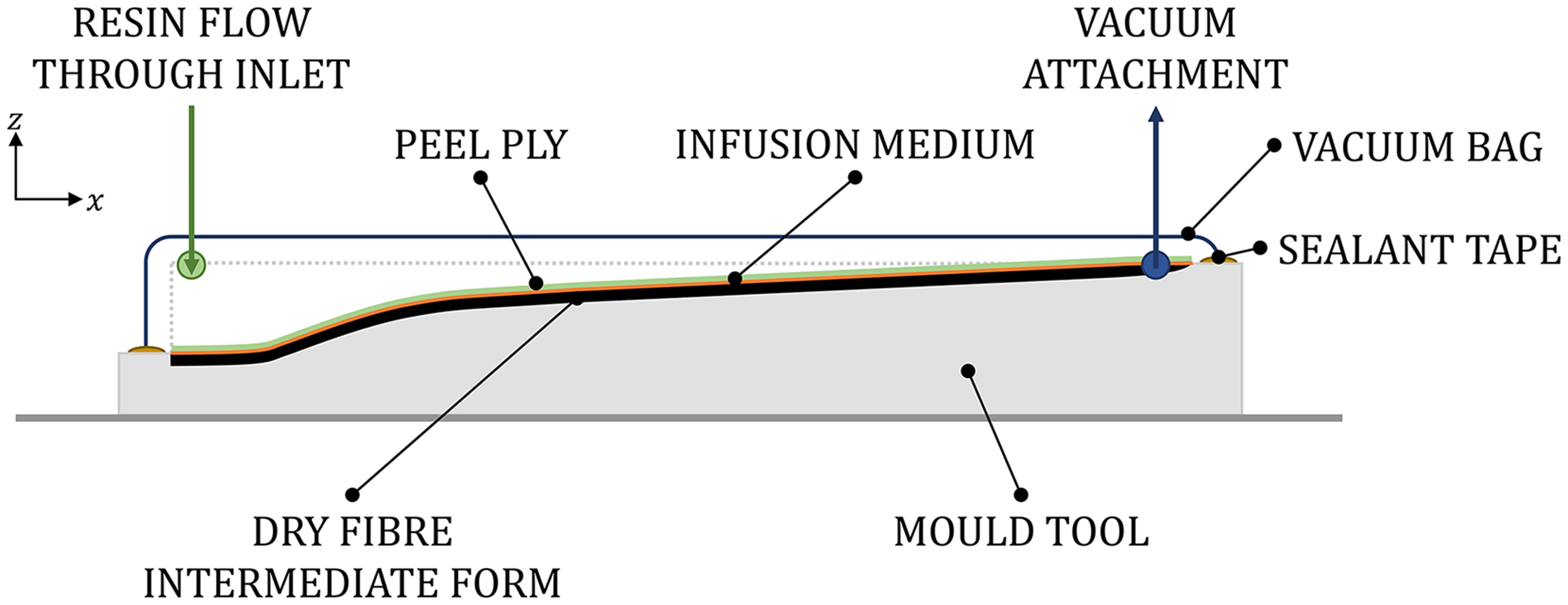
Cross-section of vacuum infusion setup for a tidal turbine blade shell. An air gap is shown between the layup and vacuum bag for illustrative purposes; in practice, the bag conforms to the layup as air is evacuated, creating a vacuum.
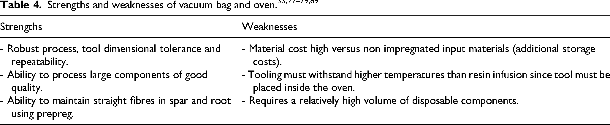
The strengths and weaknesses of using the vacuum bag process with an oven are evaluated in Table 4. The vacuum bag process is commonly used with prepreg materials to manufacture large components, such as large yachts and train components. Whilst the majority of wind turbine manufacturers utilise vacuum infusion and liquid resin, Vestas are reported to use prepregs. 8 Using prepreg material with vacuum bagging and applied heat can offer advantages comparable to autoclave processing, in which high heat and pressure are applied in a sealed vessel to produce high-quality parts. Although autoclaving is relatively costly, vacuum bagging – when used with prepreg materials and carried out in an oven – may enable significant cost and energy savings. Where cost and infrastructural constraints are key decision-making drivers, manufacturers may realise near-autoclave benefits by combining vacuum bagging and heating, achieving a standard of quality that is well-suited for the intended application, albeit slightly lower than the highest attainable quality. Improved laminate quality further enables component design optimisation – for example, through the use of thinner, higher-quality sections that achieve the same structural performance as thicker, lower-quality laminates, which would likely contain more defects. Although the prepreg materials that deliver this enhanced quality are relatively expensive, the higher material cost may be offset by a reduction in overall material consumption.
Heated moulding
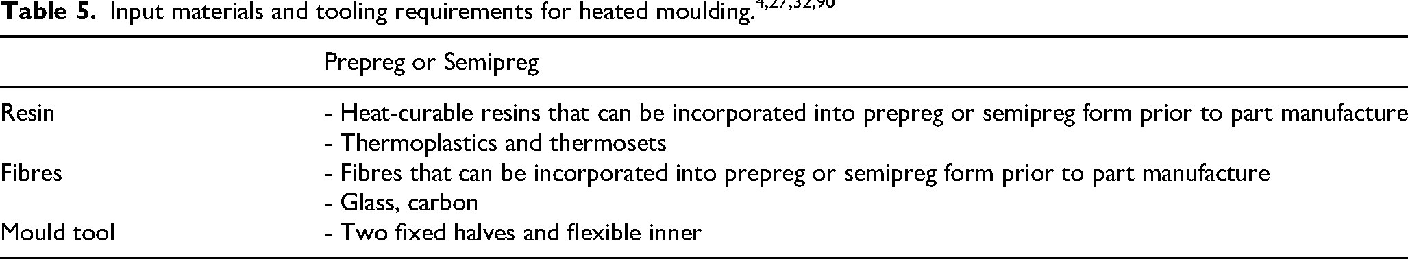
A heated ceramic-FRC mould was developed by ÉireComposites for use with semipreg materials, comprising fibres and heat-curable powdered resin or prepregs, as summarised in Table 5. Layers of the semipreg are placed into a ceramic-FRC mould, Figure 7(a), with the option to place layups for individual components in sacrificial vacuum bags, which provide additional consolidation. Applying a vacuum to the inside of the tool forces the bags outwards, taking the form of the tool, Figure 7(b). Heat is then applied to the top and bottom surfaces of layups using a combination of tool heating and hot air injection into the tool cavity. These conditions are maintained until the part has fully cured or polymerised, after which, it is left to cool before demoulding.4,27,32,90,91
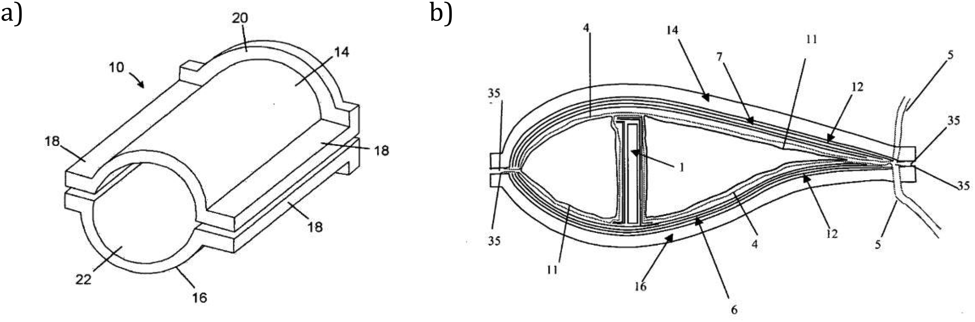
a) Heated FRC-ceramic mould tooling developed by ÉireComposites. b) Cross-section of the closed tool showing the blade shell and spar. Sacrificial bags have been applied before closing the tool. 90 Images used with permission.
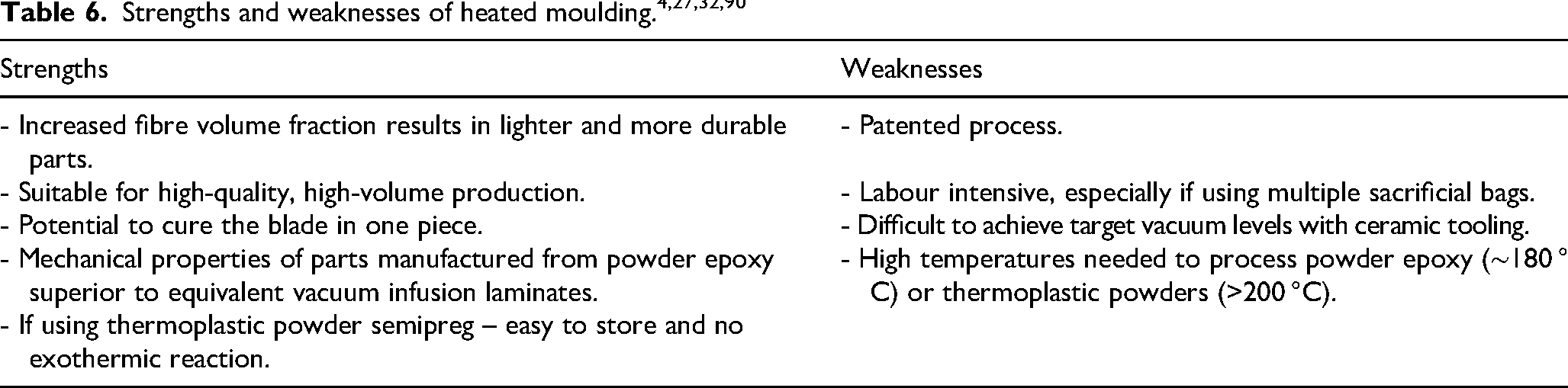
The heated mould process outlined in this section was designed specifically to manufacture wind and tidal turbine blades and is suitable for both thermoset and thermoplastic materials. This indicates significant potential, and the tool has been used to produce wind turbine blades. 91 Although the combination of ceramic and FRC materials was intended to create a strong tool that can withstand multiple uses at high temperatures, the porous nature of ceramics considerably limits the tool’s vacuum integrity, highlighted in Table 6. If this porosity were reliably resolved, the process could enable blades to be produced with shorter cycle times, reduced labour, as well as manufacturing the blade as a single piece, eliminating the need for adhesive and joining. 91 This is discussed further in the “Manufacturing a blade as a single piece” section.
Bladder moulding
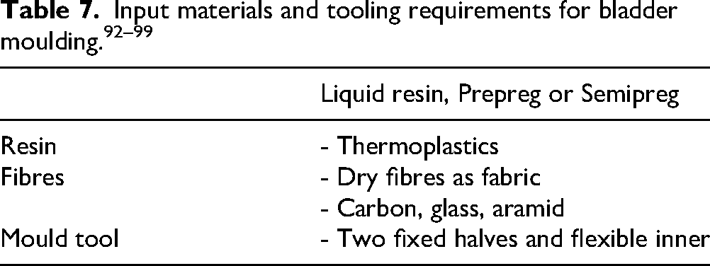
The initial setup of the bladder moulding process depends on the shape of the final part. If the prepreg or semipreg preform can be made in a near-net shape, such as a tubular section, the bladder is first inserted into the hollow preform. This assembly is then placed into the lower half of the mould, and the upper half is closed over it. Alternatively, if the preform cannot be shaped in this way due its geometry, it is laid into both the open lower and upper mould halves. The deflated bladder is positioned on top of the preform in the lower half, and the two mould halves are then clamped together. This method may be more suitable for components non-uniform in shape, such as tidal turbine blades, demonstrated in Figure 8. In both cases, air is introduced into the bladder, which expands and presses the preform against the mould surfaces, forcing it to conform to the shape of the tool. Heat is then applied through the mould, and, combined with the bladder pressure, this promotes resin flow while debulking and consolidating the layup.
The bladder moulding process can also be adapted for use with liquid resin and dry fibre preforms, replacing the prepreg or semipreg materials used in the previous method. As before, the initial layup depends on the final part shape. When using liquid resin, it is injected into the mould after the bladder has been inflated. 92– 99 Possible input materials for bladder moulding are detailed in Table 7. The bladder can be made from silicone rubber, polyamides (nylon), latex rubber, or polyetheretherketone (PEEK) with material choice determined by part geometry, processing temperatures, cost, and intended service life (reusability).93–95
Some setups incorporate air and water cooling channels in the tool, which are activated after the target temperature is reached, reducing it to the demoulding threshold. Once cooled, the bladder air supply is shut off, allowing the bladder to deflate. It is then withdrawn from the end of the part, which is subsequently post-cured if required.92–99
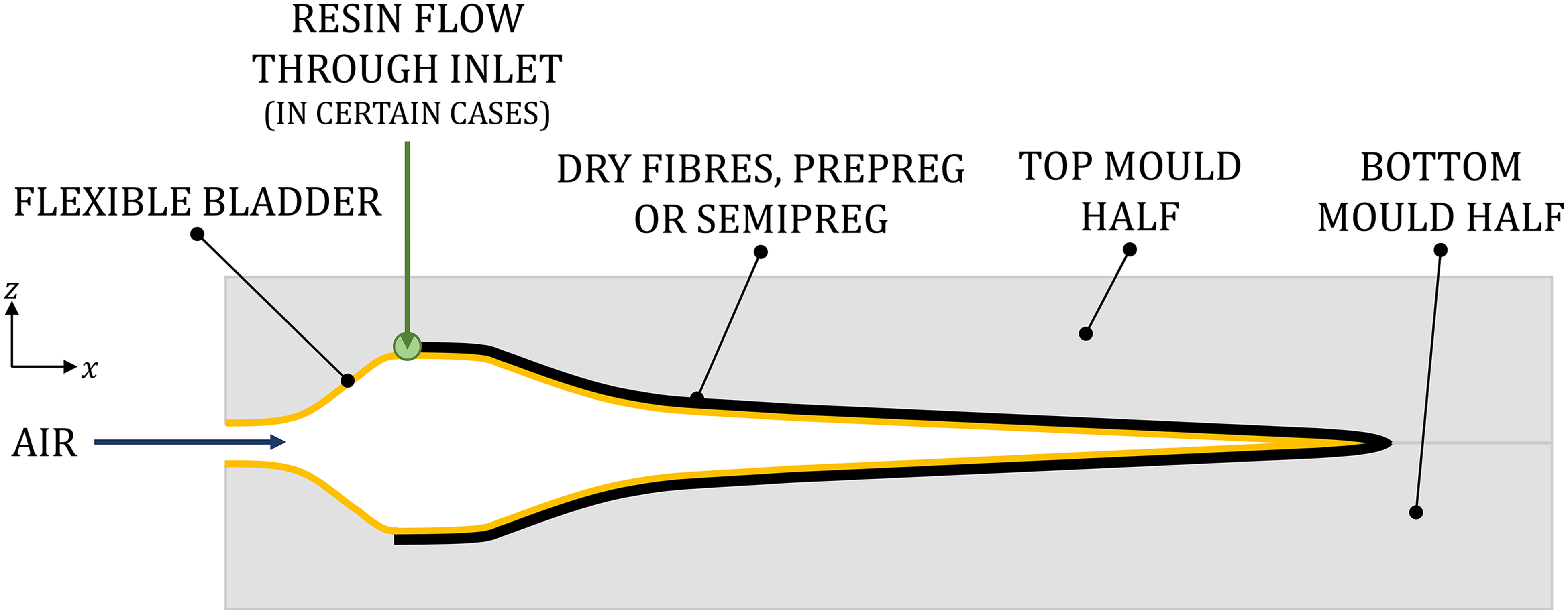
Cross-section view of bladder moulding process for a tidal turbine blade.
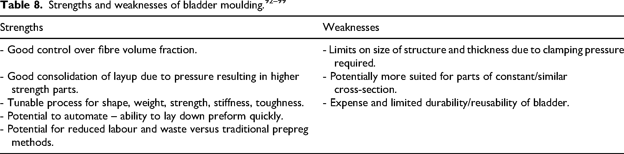
Bladder moulding is evaluated with respect to its strengths and weaknesses in Table 8. The process is currently used to manufacture hollow parts for various sectors including automotive, maritime and rail. This technology could be suited to producing tidal turbine blades in one piece, particularly for smaller structures. Heat can be applied by heating the entire tool, much like the heated moulding method discussed in the previous section, “Heated moulding”, or, more efficiently, by locally heating the surface closer to the part.90,95 Siemens’ IntegralBlade® utilises bladder moulding with liquid resin for manufacturing of large, one-piece wind turbine blades. The entire manufacturing setup is a closed mould process, and only one mould is required for the entire manufacturing process to create a wind turbine blade of 115 m in length.100–103 The use of a silicone bladder on the internal face of the part results in higher pressure on the layup, yielding better consolidation and a higher-strength part. This offers the potential to reduce the laminate thickness in a tidal turbine blade.90,104
Removing the need for joining
Wind and tidal turbine blades are typically manufactured from two vacuum-infused composite shells. Structural reinforcements and shear webs are bonded to spar caps using adhesive, which are then attached to the shells. Finally, the two shells are joined along the leading and trailing edges using additional adhesive. The adhesive is, therefore, load-bearing, and the strength of the bond line is integral to the structural integrity of the blade.8,105–107
In wind turbine blades, bond lines can be up to 30 mm thick along a 70 m blade, adding significant weight and material cost to the structure.8,27,105,106 The large adhesive thickness can lead to high temperatures and thermal gradients during curing due to exothermic reactions, resulting in variable properties across the bond line. Thick joints also require extended curing times, increasing overall process time. As such, both thermal and time management are critical to ensuring consistent bond quality and maintaining manufacturing efficiency. Epoxy adhesives are widely used due to their high strength, dimensional stability, and suitability across a broad temperature range. To avoid complex repair operations during the service life of a blade, ensuring compatibility between the adhesive joints and FRC skins is essential.8,9,105–107
Using thermoplastic resins in the manufacture of blade skins provides the opportunity to use welded joints, eliminating the need for adhesives or mechanical fasteners and thereby reducing potential weaknesses at joint interfaces. Welded joints could offer greater strength and significantly reduce process time than adhesive joining. However, most welding methods require close contact between parts, which can be challenging for large, complex structures such as blade skins. Additionally, joining thick sections presents further difficulties.9,44,108,109Resin welding has been investigated as a joining method in which dry fibres are placed along the joint of polymerised skins and infused with liquid thermoplastic resin using vacuum infusion, without requiring heat or post-processing. 108 At the joint interface, the fresh resin partially dissolves the polymerised matrix, enabling re-polymerisation and the formation of a homogenous material. The study observed that resin welding achieved comparative lap shear strengths to traditional adhesives at a bond line thickness of 1 mm. Although adhesive strength was substantially higher at a bond line thickness of 0.5 mm, it was found to be highly affected by thickness, decreasing sharply as thickness increased. 108 The authors suggest that resin welding may therefore be suited to thicker bond lines found in turbine blades, supporting further development of the method for use in large-scale structures.
Manufacturing a blade as a single piece
Manufacturing blades as a single piece eliminates risks associated with joints, bonds and weld lines, while reducing dependence on part tolerances. 22 Methods such as heated moulding, “Heated moulding”, and bladder moulding, “Bladder moulding”, lend themselves well to this design. The Siemens IntegralBlade® utilises a manufacturing method similar to bladder moulding (outlined in the “Bladder moulding” section), with the application of heat, to produce GFRP wind turbine blades using liquid epoxy resin. The same technology has been applied to create their RecyclableBlade, using Recyclamine-based epoxy resin.61,62,100–103 As part of the European Tidal Stream Industry Energiser Project (TIGER), a team from the University of Edinburgh, FastBlade, and Tocardo Turbines manufactured four monolithic tidal turbine blades for QED Naval. Each blade measures approximately 3 m in length, and the new structural design has been reported to reduce weight, material usage, and manufacturing costs.22,110
Conclusions
Tidal turbine blades are conventionally manufactured from thermoset fibre-reinforced (FRC) materials using vacuum infusion processing. While much of the existing literature focuses on the manufacture of wind turbine blades, the apparent design similarities between wind and tidal blades are outweighed by the markedly different operational conditions and scale, leading to distinct manufacturing requirements and presenting opportunities for the tidal sector to adapt lessons from other industries with transferable technologies. Innovations in constituent materials and their forms, advances in manufacturing processes, and the entry of new manufacturers into the blade sector create scope to question and enhance current manufacturing and assembly methods. The relative commercial immaturity of tidal technology allows circularity to be considered from the initial stages, adopting a systems approach that aims to minimise environmental impact and waste whilst maximising the utility of resources across the entire product lifecycle. When considering material selection and manufacturing process together, the combination of thermoset FRC materials and vacuum infusion may not be the most suitable, with potential for improvements in part quality, structural performance, and material efficiency.
This paper presents an overview of current materials, vacuum infusion manufacturing, and assembly processes to guide new and existing entrants to the sector. In particular, the review of material advances applicable to tidal turbine blades highlighted that while there is significant potential, further development is required to ensure FRC blade shells are of suitable quality and compatible with other components. Compatibility may be achieved by modifying the blade shells or by adapting adhesives, fillers, and paints to suit the shell material, ensuring long-term durability. A range of composite manufacturing processes was considered, with three alternative methods evaluated for their suitability in tidal turbine blade production. Among these, the use of prepreg or semipreg materials combined with vacuum bagging and oven curing emerged as the most viable alternative to vacuum infusion of liquid resin, with minimal further development required. This method may offer similar benefits to autoclave processing but at a lower cost, making it a promising approach for improving tidal turbine blade manufacturing. Given the diversity of turbine technologies in the sector, the optimal combination and selection of materials and manufacturing methods will vary. This study equips manufacturers to make informed, strategic decisions that will ultimately enhance tidal turbine blade production.
Footnotes
Ethical considerations
Not applicable.
Consent to participate
Not applicable.
Consent for publication
Not applicable.
Author contributions
Funding
The authors disclosed receipt of the following financial support for the research, authorship, and/or publication of this article: The authors are grateful to EPSRC and NERC for funding for the Industrial CDT for Offshore Renewable Energy (EP/S023933/1) [I.L.M.S.] and financial support from the School of Engineering, University of Edinburgh through an Elizabeth Georgeson Fellowship [W.O.].
Declaration of conflicting interests
The authors declared no potential conflicts of interest with respect to the research, authorship, and/or publication of this article.
Data availability
Not applicable.