
Abstract
In this study, aluminum nitride (AlN) modified carbon fiber heating elements (HE) were used to connect carbon fiber reinforced poly-ether-ether-ketone (CF/PEEK) composites by resistance welding. The effects of AlN content and environmental conditions on the lap shear strength (LSS) of resistance welding composites were investigated by preparing welded joints with different AlN content. The results show that the LSS of the welded joint increases rapidly with the increase of AlN content. When the content of AlN is 5 wt.%, the maximum strength reaches 30.63 MPa. The welded joints were then placed in room temperature (25°C, 50% relative humidity (RH)) and artificial aging chamber (85°C, 90%RH) for 28 days, respectively, and tested in the temperature range of −30°C to 145°C. It is found that with the increase of test temperature, the LSS under the two environmental conditions shows a decreasing trend. High temperature and moisture absorption will have a superimposed negative impact on the LSS of the welded joint. At 145°C, the strength of the sample under elevated temperature wet (ETW) environment is the lowest, which is 21.61 MPa. The SEM analysis of the fracture surface of the joint shows that the main failure mechanism of the joint is the cohesive failure of HE. The main reasons for the degradation of interface bonding properties are wet heat aging and high temperature environment.
Introduction
Thermoplastic composites have gained wide attention in aerospace, automotive marine and other fields due to their excellent properties like high specific strength, excellent creep resistance, designability, and weldability.1–3 As known, the connections of composite components play a vital role in the design and manufacture of composite monolithic structures. Mechanical fastening is currently the primary joining method used in the aerospace industry, but some issues such as stress concentration, galvanic corrosion, mismatched coefficients of thermal expansion, and damage to reinforcing fibers caused by drilling can lead to the poor connecting performance.4,5 Adhesive bonding is also a common process for connecting carbon fiber reinforced thermoplastic composites (CFRTP), but this process is usually complicated, need for high-temperature pretreatment and activation of weakly polar surfaces.6,7 In recent years, fusion welding has been regarded as an effective alternative strategy for joining thermoplastic composites because their polymer matrix can be melted and then solidified. 8 Among various fusion welding methods, resistance welding has been widely concerned and primarily explored due to its fast speed, low cost, and suitability for large components.9,10
In resistance welding, an electric current passing through a heating element (HE) produces Joule heat, leading to HE melting under a pressure, as well as the interfaces of the connecting parts. Subsequently, the current ceases and the polymer matrix is cooled and solidified. Then, the resistance welding of thermoplastic composites is completed. Recently, studies on resistance welding of thermoplastic composites are concentrated in the types of HEs, the optimization of process parameters, the characterization of joint strength and failure modes at room temperature. Howie et al. 11 optimized the welding process of Radel®/polyarylene sulfone and polysulfone dual polymer systems by statistical experimental design methods, providing a feasibility analysis for resistance welding of dual polymer systems. McKnight et al. 12 successfully achieved the welding of large-size CF/PEEK composite joints using the SRW process. In addition, Don et al. 13 analyzed the effects of welding time, initial curing pressure and heat generation rate on the welding performance of AS4/PEEK unidirectional laminates and quasi-isotropic laminates, and Jakobsen et al. 14 constructed a two-dimensional transient thermal model to predict the temperature distribution and melting behavior during welding and optimize welding parameters.
At present, carbon fiber and metal mesh are the most commonly used conductive materials in HE. Compared with the problems of heterogeneous interface incompatibility, impurity introduction and electrochemical corrosion of metal mesh, 15 carbon fiber has gradually become a research hotspot in this field due to its excellent corrosion resistance, low thermal expansion coefficient, conductive anisotropy and compatibility with parent materials. 16 Early studies 17 revealed the thermal conductivity anisotropy of carbon fiber through finite element modeling, and proved that although high power density can shorten the melting time, it is easy to cause local overheating and polymer degradation. Eveno et al. 18 found that the use of low power combined with long welding time can improve temperature uniformity, and crimping metal alloy at the fiber ends mitigates fiber oxidation. Recent studies have focused on the structural-functional synergistic design of carbon fiber fabric. Sun et al. 19 studied the synergistic effect of carbon fiber fabric (CFF) and hexagonal boron nitride (h-BN) modified polyetherimide (PEI) insulating film in resistance welding, finding that the use of CFF with h-BN/PEI composite films can significantly improve the lap shear strength (LSS) of the welded joint. In the CF/PEEK composite resistance welding, the low thermal conductivity of PEEK (0.23 W mK−1 at room temperature) significantly limits heat transfer efficiency during the heating process, as it functions as an insulating layer for the HE. Currently, there are two main methods to improve the thermal conductivity of polymers: increasing the order and crystallinity of polymer chains, and incorporating high thermal conductivity fillers. 20 Among the various inorganic fillers, aluminum nitride (AlN) is considered to be an ideal thermal conductive filler due to its high thermal conductivity (about 150–200 W/(m·K)), high insulation and low thermal expansion coefficient.
However, considering the prolonged service, the performance of composites and their joints will be suppressed when they encounter intricate environments including temperature, humidity, radiation, and chemical erosion. Therefore, it is necessary to explore the degradation mechanisms in these environments and the impact of degeneration on their long-term mechanical properties. Accelerated aging methods were usually applied to examine the mechanical evolution with testing surrounding. That is to say, measuring samples are exposed to extreme conditions for a short period to evaluate the environmental impact on material properties. Current reports on the aging behavior of composites mainly focus on composite laminates. To illustrate, Bayerl et al. 21 investigated the thermal degradation behavior of CF/PEEK under short-term heating, observing severe surface damage, fiber exposure, hole formation, chemical bond alterations. Prolonged irradiation duration, the polymer matrix was severely damaged. The effect of temperature on the low-temperature impact behavior of CF/PEEK composites showed that increasing temperature would reduce the impact energy and increase the permanent indentation, while exhibiting negligible influence on melting point and crystallinity. 22 Whereas, the aging behavior of resistance welded polymer composite joints were seldom reported. Koutras et al. 23 conducted a systematic study on the effect of temperature on the strength of GF/PPS welded joints, revealing the complex relationship between temperature and joint performance. Building upon this foundation, Rohart et al. 24 explored the aging behavior under different temperature and humidity coupling environments through multi-factor coupling experiments, and clarified the microscopic influence mechanism of environmental factors on the joint interface performance under the synergistic effect of moisture and heat. Shen et al. 25 investigated the formation mechanism and failure modes of resistance welded CF/PEEK joints at different temperatures through experimental and numerical simulation methods. They introduced genetic algorithm-optimized artificial neural networks to predict the strength of welded joints, providing theoretical support for the application of composites in high temperature environments.
The major objective of this study is to evaluate the effects of aluminum nitride (AlN) content and environmental conditions on shear strength of resistance welded joints of CF/PEEK composites. CF/AlN-PEEK heating elements were prepared with a powder suspension impregnation process and resistance welding was performed on CF/PEEK composite laminates. Subsequently, the welded joints were exposed to two different environmental conditions: room temperature dry (RTD) and elevated temperature wet (ETW). To reveal shear strength and failure modes, tensile shear tests, ultrasonic C-scan and scanning electron microscope examination were performed on CF/PEEK lap joints at various temperatures.
Experimental Procedure
Materials
The carbon fiber fabric model was T300, the fabric architecture was plain weave, the fabric surface density is 1.76 g cm−3, and was made by Toray Composite Materials America. The CF/PEEK laminate (prepreg layer was 0°) was made by AVIC Composites Co., Ltd. and its size was 100 mm × 20 mm × 2 mm. PEEK powder (KetaSpire® KT-880UFP) was produced by Suwei, USA and its specific gravity was 1.30 g cm−3. AlN whiskers were purchased from Nangong Fenghui Nanotechnology Co., Ltd. and its diameter was 0.1 to 0.5 μm. γ-Aminopropyl triethoxysilane (KH550) was purchased from Shanghai Aladdin Biochemical Technology Co., Ltd.
Preparation of Heating Elements
The preparation process of a HE is depicted in Figure 1. Initially, AlN whisker suspensions with different silane contents (0 wt.%, 3 wt.%, 5 wt.%, 7 wt.%, 9 wt.%) were prepared. Taking AlN modified with 5 wt.% silane as an example (denoted as AlN5%), the preparation process was displayed as following. 0.5 g AlN whiskers were placed into a beaker, followed by the addition of 0.025 g KH-550 and 5 mL anhydrous ethanol. The mixture was rapidly stirred for 4 h to enhance the dispersion of AlN, resulting in a modified AlN5% suspension. Simultaneously, 9.5 g PEEK powder was added to a beaker with 30 mL of anhydrous ethanol, and the PEEK suspension was obtained by magnetic stirring for 4 h. Subsequently, the AlN and PEEK suspensions were combined in a beaker, forming an AlN5%-PEEK suspension through ultrasonic dispersion for 1 h. Next, the carbon cloth was immersed in AlN5%-PEEK suspension for 10 min, then taken out and dried in an oven at 200°C. The remaining AlN5%-PEEK suspension was further heated and stirred to form a uniform slurry. The mold was tiled on the release cloth, and the slurry was coated in the mold cavity, then dried in a vacuum oven for 24 h at 60°C. Finally, CF/AlN5%-PEEK heating element was prepared by hot pressing at 380°C, 10 MPa for 10 min, with the layers aligned in the sequence of hot platen-AlN5%-PEEK-carbon cloth-AlN5%-PEEK-hot platen. Flow chart of preparing HEs.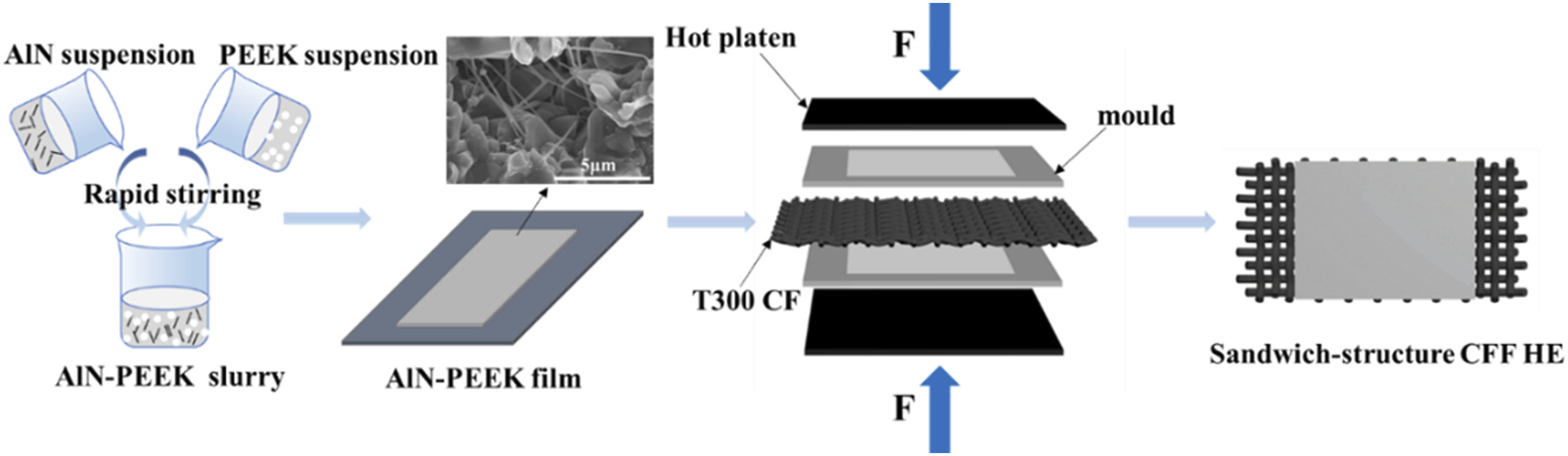
Resistance Welding Process
The as-prepared HE was cut into a size of 50 mm × 20 mm and positioned between two CF/PEEK laminates to form an overlap joint of 20 mm × 20 mm. Then, it was placed in a self-made resistance welding device and a pressure of 1 MPa was applied to the lap joint for electric heating. After cooling at room temperature, a single lap welded joint specimen of CF/PEEK laminates was obtained (see Figure 2). Before welding, the laminates were degreased with acetone. The welding parameters were determined from previous optimization experiments, with a welding current of 14 A and a welding time of 114 s. Diagram of the single lap welded joint specimen.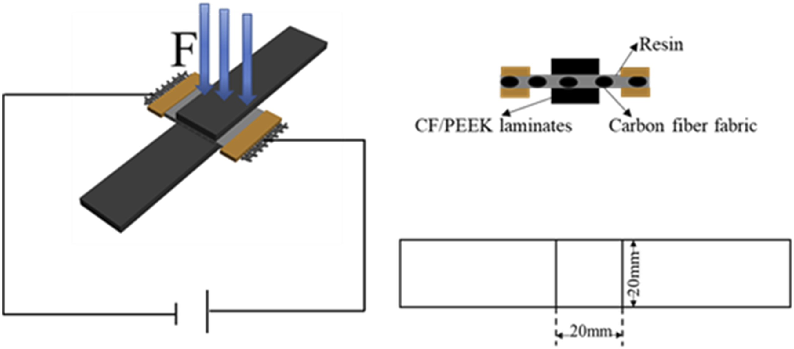
Environmental Conditioning

Conditioning and testing temperatures for all specimens.
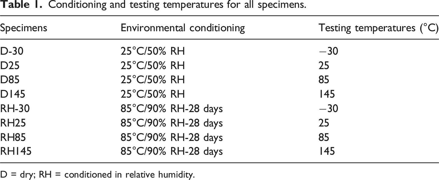
D = dry; RH = conditioned in relative humidity.
Material Characterization
Thermal Performance Testing
The thermal conductivity of AlN-PEEK films was measured with a thermal conductivity meter (Hot Disk TPS 2500S) in order to examine the influence of AlN content on the heat transfer properties of HEs. The viscoelastic properties and the glass transition temperature of the composite material were assessed before and after aging using dynamic mechanical analysis (DMA, Pyris Diamond). The specimens with the size of 55 × 20 × 2 mm were tested with the double cantilever beam method under a heating rate of 3°C min−1 in the temperature range from 50°C to 250°C.
Ultrasonic Nondestructive Testing
Ultrasonic testing was conducted on welded joints fabricated from HEs with varying AlN contents. An ultrasonic flaw detector (EPOCH 1000i) was utilized to detect and analyze internal defects in the welded region.
Lap Shear Tests
In accordance with ASTM D5868-2014, the single LSS of specimens was evaluated by using an electronic universal testing machine (LE5105) with a loading rate of 1 mm min−1. The specimens were equilibrated at the test temperature for 30 min before testing to ensure uniform temperature distribution throughout each specimen. Each testing group contained five specimens. Single lap shear strength is calculated as: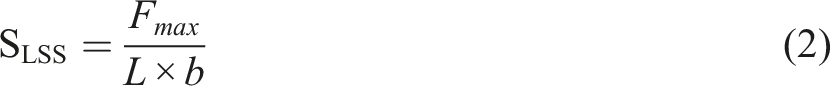
Microstructure and Fracture Analysis
The fracture morphology of specimens after mechanical testing was observed with a field emission scanning electron microscope (FEI Quanta-250) to analyze failure types and mechanisms.
Results and Discussion
Performance Analysis of Heating Elements
To evaluate the influence of AlN whiskers on the tensile strength and thermal conductivity of AlN-PEEK films and CF/AlN/PEEK composites with different AlN contents (0 wt.%, 3 wt.%, 5 wt.%, 7 wt.%, and 9 wt.%) were prepared by hot pressing. Figures 3(a) and 3(b) demonstrates the effect of AlN content on the thermal conductivity of the composites. With the increase of AlN content, the thermal conductivity of AlN-PEEK and CF/AlN/PEEK composites gradually enhanced, eventually reached the maximum values of 0.3212 W mK−1 and 0.3971 W mK−1. Due to the synergistic thermal conductivity effect of carbon fiber and AlN, the thermal conductivity of the CF/AlN/PEEK system was significantly increased from 0.3035 W mK−1 to 0.3971 W mK−1, an increase of 23.57%. This enhanced thermal conductivity accelerates heat transfer during resistance welding of CF/PEEK composites, thereby optimizing the temperature distribution. This optimization helps to prevent the ablation of carbon cloth due to local overheating and reduces interface fusion defects caused by insufficient heat. (a) Thermal conductivity of CF/PEEK (b) Thermal conductivity of CF/AIN/PEEK (c) Tensile strength of CF/PEEK (d) Stress-strain curve of CF/PEEK.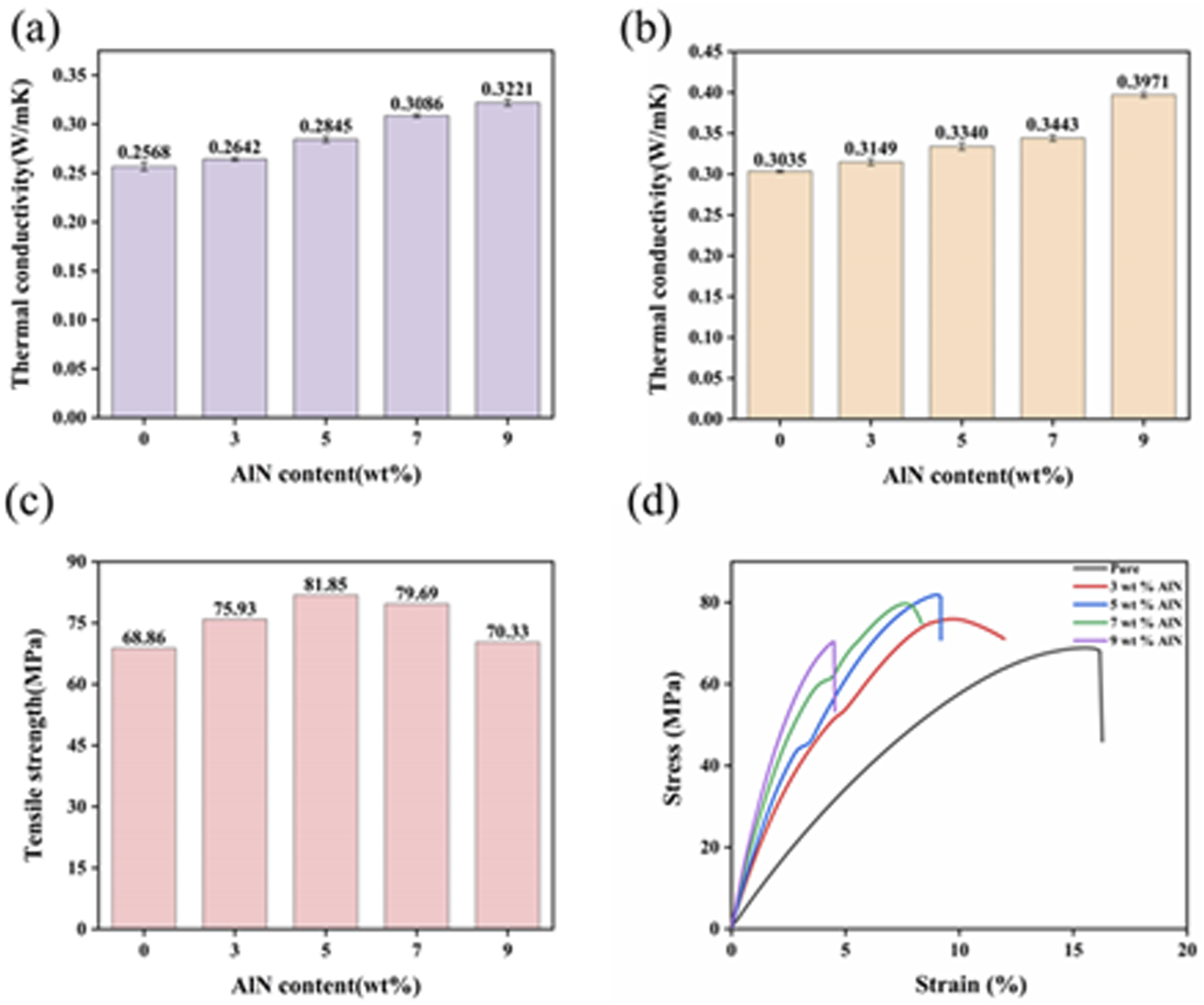
Figure 3(c) demonstrates that the tensile strength of AlN-PEEK composites increased with AlN content, achieving a peak value of 81.85 MPa. Nevertheless, the tensile strength declined at AlN content above 5 wt.%. This trend may be interpreted as follows. A low content of filler particles acted as a bridge for crack bridging, thereby preventing crack extension. As the filler content increased, the continuity of the PEEK matrix was diminished, causing internal stress concentrations and defects. The stress concentrations and defects escalated as the gap between the filler and the PEEK matrix was widened, embrittling the PEEK composite and consequently decreasing its tensile strength. As can be seen from Figure 3(d), with the increase of AlN content, the elastic modulus gradually increased and the elongation at break gradually decreased. As an inorganic filler, AlN has high rigidity and strength. When the AlN content increased, it more effectively restricted the movement of the PEEK molecular chains, thereby enhancing the overall rigidity of the material and leading to an increased elastic modulus. At the same time, AlN filled the free volume of the matrix, restricted the extension and slippage of the PEEK molecular chains, and reduces ductility.
Effects of AlN Content on the Properties of Welded Joints
To investigate the effect of AlN content on the properties of welded joints, resistance welded joints with varying AlN contents were fabricated and assessed with non-destructive testing methods (see Figure 4). Figure 4(a) illustrates ultrasonic C-scan image of welded joints without AlN. Severe defective zones in the interior and moderate defective zones at the edges were observed, indicating that some resin within the welded joints did not achieve a plastic state in the absence of AlN. Resin at the joint edges partially melted, thus leading to inadequate wetting of carbon fiber fabric and the poor joint quality. Figures 4(b)–4(e) depict welded joints with different AlN contents of 3 wt.%, 5 wt.%, 7 wt.%, and 9 wt.%. The joints with 5 wt.% AlN exhibited the minimal thermal damage, characterized by negligible severe defects and scant moderate defects at the edges. In a word, under consistent welding parameters, the appropriate addition of AlN with high thermal conductivity improved heat transfer efficiency. This improvement in heat transfer resulted in the more uniform heat distribution, as well as the lower risk of localized overheating and severe defects. Ultrasonic C-scan images of single lap welded joints with different AlN contents: (a) 0 wt.% AlN; (b) 3 wt.% AlN; (c) 5 wt.% AlN; (d) 7 wt.% AlN; (e) 9 wt.% AlN (red indicates zero defect; yellow indicates moderate defect; blue indicates severe defect).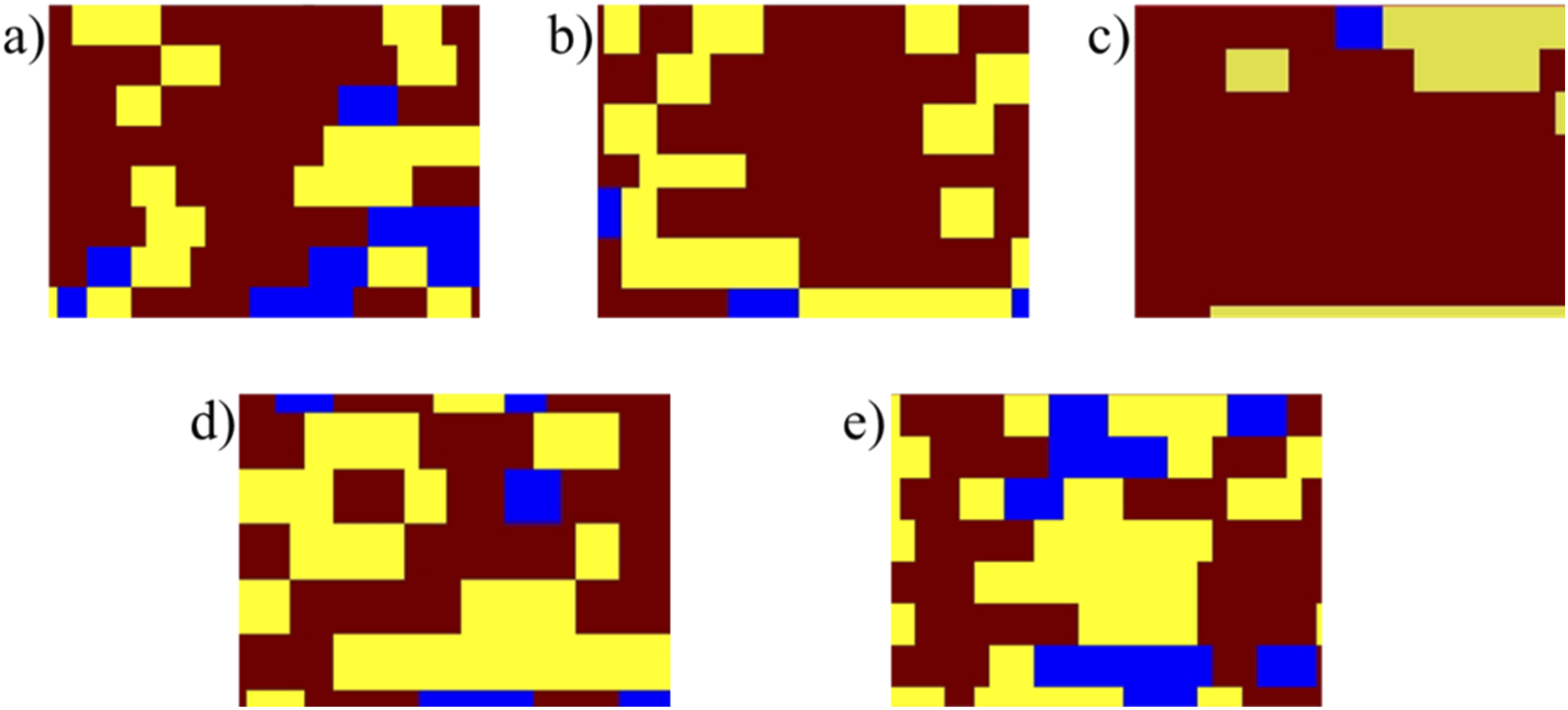
Figure 5 showcases the tensile strength of CF/PEEK composites welded joints with different AlN contents. As it can be seen, the LSS initially increased and subsequently decreased with increasing AlN content. The LSS of the welded joint with 5 wt.% AlN achieved 30.63 MPa, which was 41% higher than that of the joint without AlN. LSS of welded joints with different AlN contents.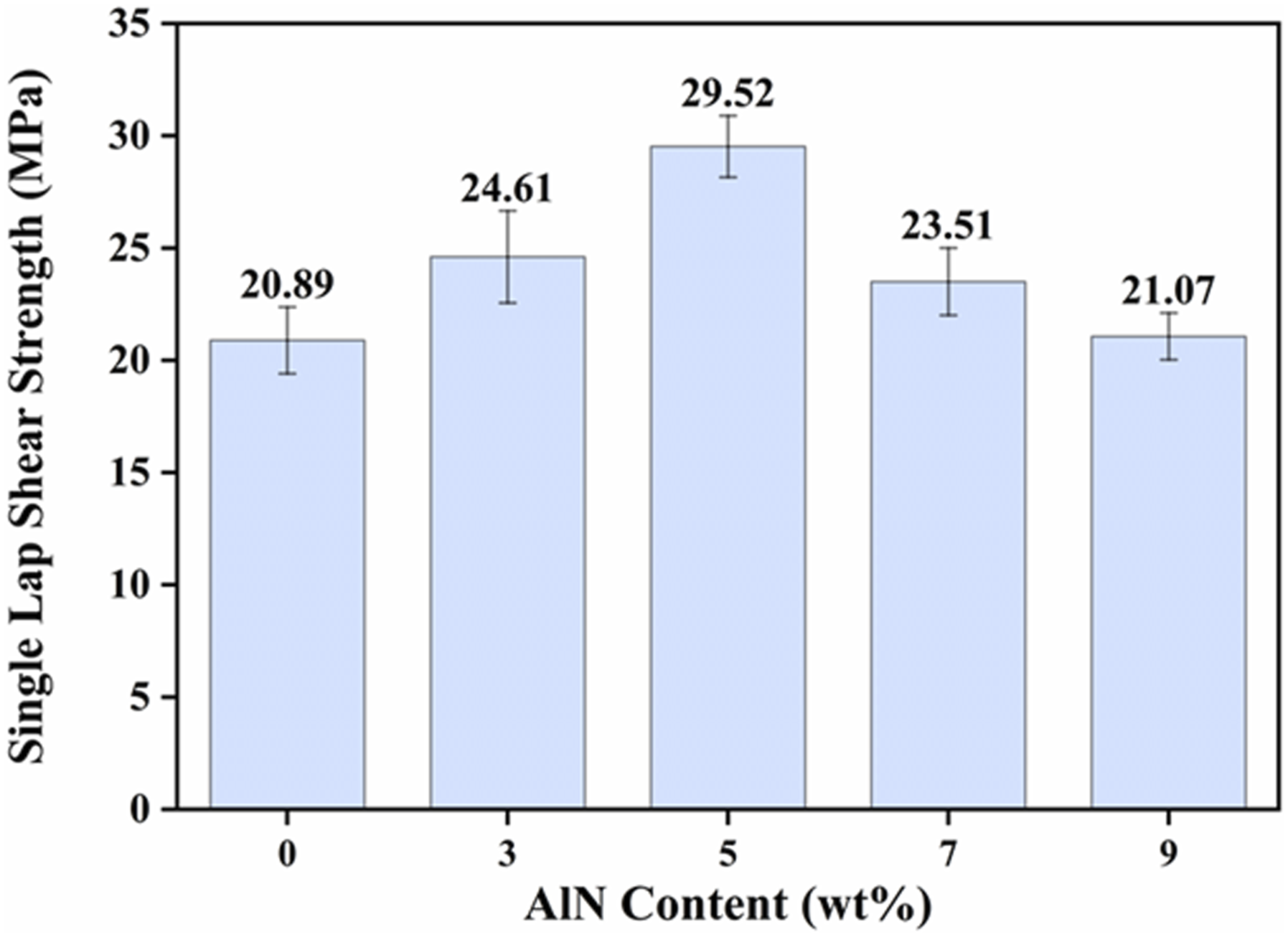
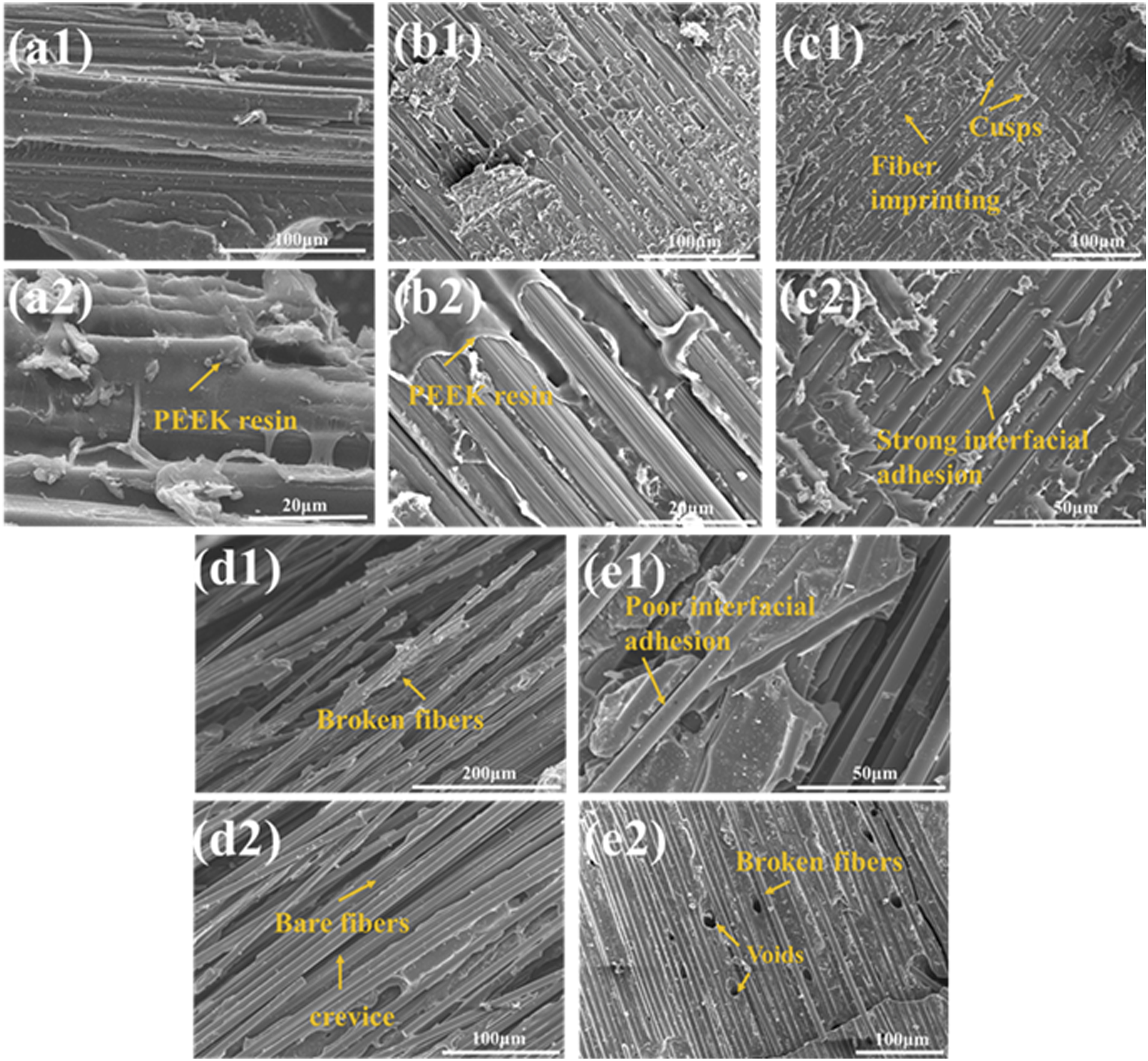
Figure 6 reveals the incomplete resin melting in joints without AlN addition, suggesting that the interfacial temperature did not reach the resin melting temperature. This thermal insufficiency led to interface failure and cohesive failure of the HE, and consequently reduced joint strength. With increasing AlN content, the heat transfer efficiency of the weld interface was improved, promoting greater resin melting. However, excessive AlN affected the heat distribution during welding. Inadequately heated areas caused insufficient resin melting, while overheated regions resulted in carbon fiber ablation and matrix thermal degradation, diminishing the joint strength. The fracture morphology (Figures 7(c1) and 7(c2)) exhibited distinct fiber imprints and a tightly bonded interface on the surface of the 5 wt.% AlN specimens. This observation indicated that the load was effectively transferred from the resin matrix to the carbon fiber, reducing stress concentration and enhancing the joint’s tensile strength capacity. At elevated AlN loadings, bare fiber fractures and voids appeared (Figures 7(d1) and 7(d2)). This phenomenon occured because excessive AlN tended to form agglomerates, which hindered resin flow and generated voids during the curing process. These voids acted as sources of stress concentration, affecting matrix uniformity and consequently diminishing the bonding strength at the welding interface. The macro morphology of fracture surface of CF/PEEK composite welded joints with different AlN content. Sem images of fracture surface of welded CF/PEEK composites with different AlN content:: (a1)-(a2) 0 wt.% AlN; (b1)-(b2) 3 wt.% AlN; (c1)-(c2) 5 wt.% AlN; (d1)-(d2) 7 wt.% AlN; (e1)-(e2) 9 wt.% AlN.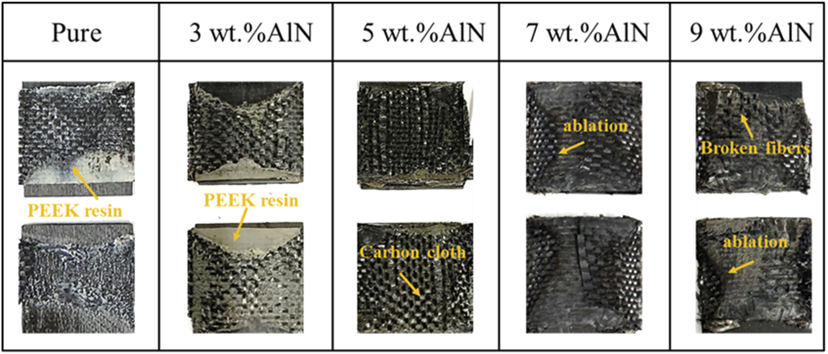
Effects of a Hygrothermal Environment on the Joint Performance
The above analysis indicated that the welded joint with 5 wt.% AlN exhibited the optimal performance. Therefore, CF/AlN5%-PEEK heating element was used for resistance welding of CF/PEEK composites. Subsequently, the specimens were subjected to a hygrothermal environment to further assess the influence of different conditions on the joint performance.
Hygroscopicity
Moisture is absorbed in polymers via a diffusion process and water molecules migrate from the areas of high moisture concentration to those of lower moisture content. The diffusion process depends on temperature and relative hygroscopicity and can be fitted by Fick ‘s second law.26–28 Assuming that the composite material behaves as a single-phase Fickian material, its behavior conforms to equation (3):


Equation (6) can be obtained by separating variables:
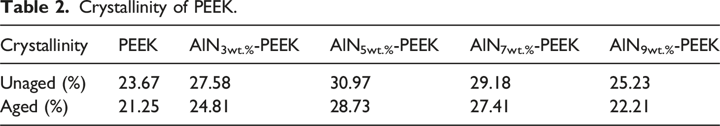
Curve fitting was performed with the least squares method in the iterative steps in order to determine whether the material had reached the moisture absorption equilibrium. According to ASTM D5229 standard, it is believed that the moisture absorption equilibrium is achieved when the interval between two measurements is less than 0.01 wt.%. Taking the 5 wt. %AlN joint as an example, the initial moisture content of the material was 0.02 g, and the moisture content after hygrothermal aging was 0.035g. Figure 8 makes it clear that the mass of CF/PEEK composite specimens in the environmental chamber was stabilized after 10 days. The moisture absorption rate of the material firstly increased significantly, was then stable, and eventually reached a saturation state. The curve was in accordance with the Fickian diffusion model. It can be seen from Table 2 that the crystallinity of PEEK increases after adding AlN. This was because AlN acted as a heterogeneous nucleating agent, providing nucleation points for crystal growth, thereby promoting the crystallization of PEEK. Additionally, the addition of AlN shortened the crystallization half-life of PEEK. At the same cooling rate, the PEEK molecular chain had more time to crystallize, resulting in enhanced crystallinity.
29
The amorphous regions of PEEK exhibit higher hygroscopicity, and molecular chain segment reorganization during hydrothermal treatment facilitates crystallinity enhancement, consequently diminishing both hygroscopic capacity and humidity saturation levels. Hygroscopic curves of CF/PEEK composites with different AlN content. Crystallinity of PEEK.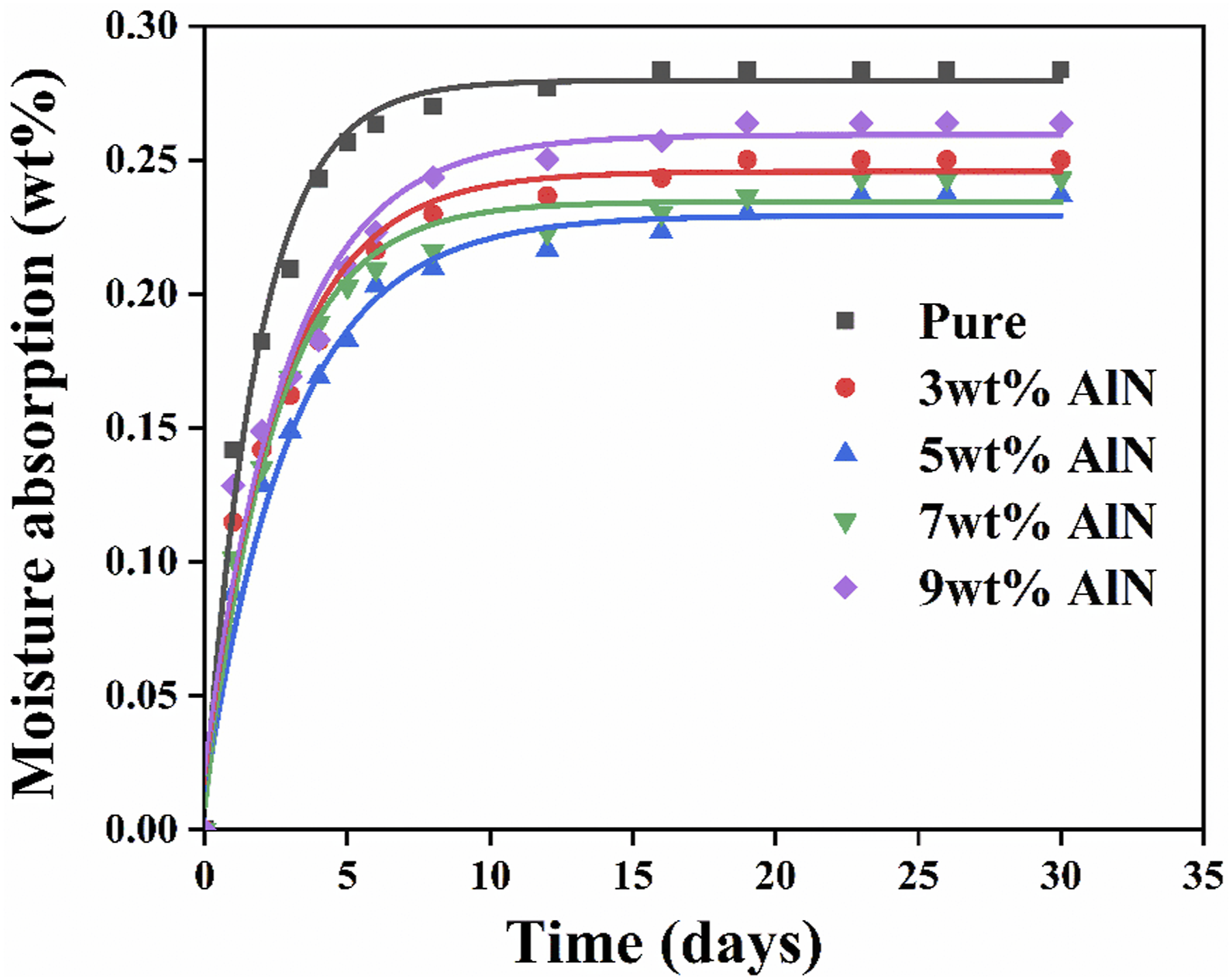
Dynamic Mechanical Analysis (DMA)
The DMA curves of CF/PEEK composites under RTD and ETW conditions are shown in Figure 9 The storage modulus (E′) and loss modulus (E″) of the specimens in the ETW environment were lower than those in the RTD environment, which is associated with the degradation of the fiber-matrix interface. In the ETW environment, interfacial debonding between fibers and resin might occur due to the differences in thermal expansion coefficient. Moisture could penetrate the fiber-matrix interface, thereby weakening the adhesion and reducing load transfer efficiency.
30
Consequently, energy storage modulus and loss modulus decreased. The loss factor (tan δ) of the specimens in the ETW environment showcased a higher value (see Figure 7(c)), indicating that energy dissipation of hygrothermal specimens was higher than that of dry specimens. This difference can be attributed to enhanced molecular chain mobility under hygrothermal conditions, triggering off high heat dissipation and tanδ. The Tg, represented by the peak value of tanδ, is slightly lower for specimens in the ETW environment compared to that in the RTD environment. This effect can be a consequence of the hygrothermal moisture absorption that plasticized the polymer,
31
which had been observed by Guermazi groups.
32
In short, hygrothermal conditioning plasticized the thermoplastic polymer matrix and facilitated the movement of polymer chains at elevated temperatures. Dynamic mechanical analysis (DMA) results of dry specimens and saturated specimens: (a) storage modulus, (b) loss modulus, and (c) loss factor or tangent delta.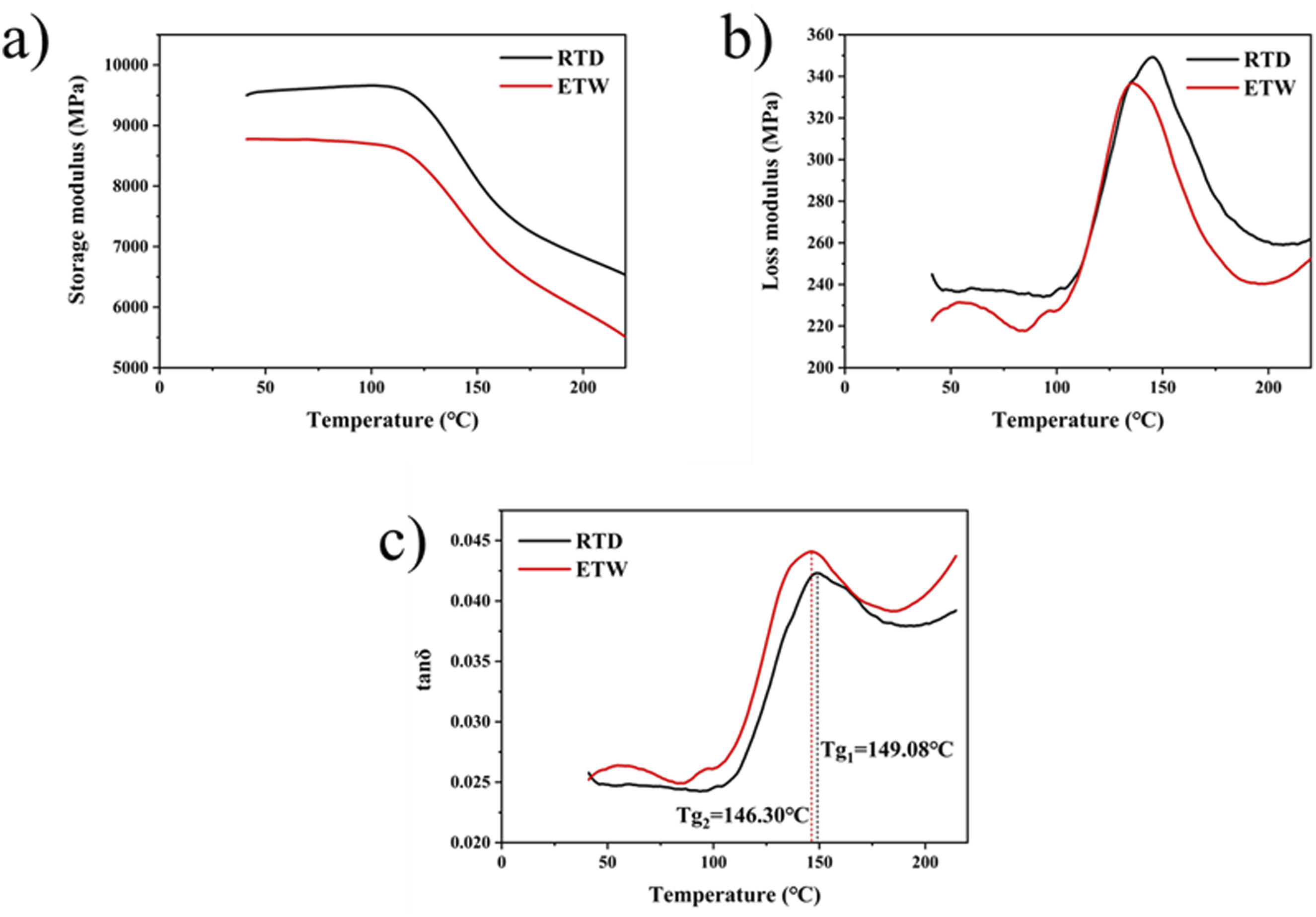
Single LSS of Welded Joints
Figure 10 exhibits LSS of welded joints under RTD and ETW conditions at −30°C, 25°C, 85°C, and 145°C, respectively. With the rise in temperature, LSS values of samples under the two environments generally displayed the downward trend. LSS of RTD joint tested at 145°C was 24.13 MPa, decreasing by 18% compared to that tested at 25°C. At the same temperature, LSS values of ETW joints were lower than those of RTD joints. At −30°C, 25°C, 85°C, and 145°C, the average LSS differences were merely 1.9%, 3.05%, 7.9%, and 10.4%, respectively, meaning that the mechanical properties of CF/PEEK resistance welded joints reduced evidently by suffering from the high temperature and moisture. The reason can be interpreted as follows. After moisture saturation was reached, the fusion welded joint still maintained strong bonding and exhibited minimal changes in interfacial strength. Therefore, LSS of ETW sample at low temperature showed slight difference from RTD sample. As temperature escalates, the absorbed water was accelerated to enter the defects such as cracks and voids in the welded joint. Moreover, the thermal expansion coefficient of PEEK resin was significantly different from that of carbon cloth.
33
Given these issues, high wet stress and thermal stress were generated within the joint and substantially reduced the shear strength of composite resistance welded joint. Single LSS of welded joints of CF/PEEK laminates in different environments and test temperatures.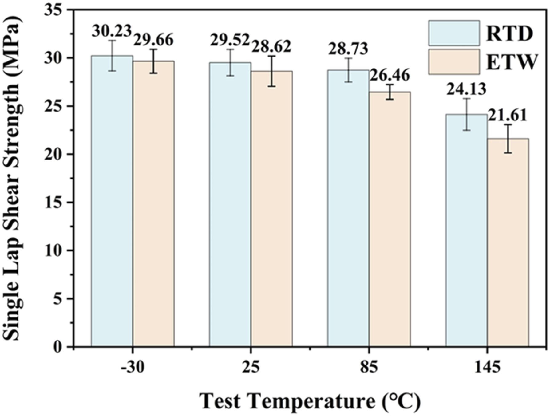
Failure Modes of Welded Joints
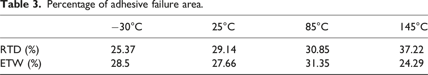
Figure 11 demonstrates the fracture surface of the welded joints of the specimens treated under RTD and ETW. The failure modes of the specimens exposed to two environmental treatments were predominantly the cohesive failure mode of HE, together with some HE interface and fiber failures. In the specimens tested at −30°C, within the joints under both environments, carbon cloth was torn in the shear direction and evenly distributed on the adherends. As temperature rose, the primary failure mode was the cohesive failure of HE, while the tearing direction of carbon cloth became random. The fractured fibers were visible at the lateral ends of the joint and in the central region of the weld area. As can be seen from Table 3, the proportion of adhesive in the ETW was higher than that in the unaged environment. As the temperature increased, the adhesive failure area also increased. Although the adhesive failure area of the sample in the ETW environment was smaller at 145°C, residual resin was still visible on the fibers. The phenomenon may be explained by the softening of the resin at this temperature, which led to a transformation of the main failure mode of the joint in the ETW environment into the interface failure of HE. Additionally, under high-temperature and high-humidity conditions, the hygrothermal stress on the fiber and PEEK likely contributed to a decrease in the bonding at the fiber/matrix interface. Consequently, the hygrothermal stress failed to transmit efficiently during tension and resulted in fiber detachment from the matrix. Fractures of the welded joints of specimens treated under different environmental conditions and subjected to lap shear tests at different temperatures. Percentage of adhesive failure area.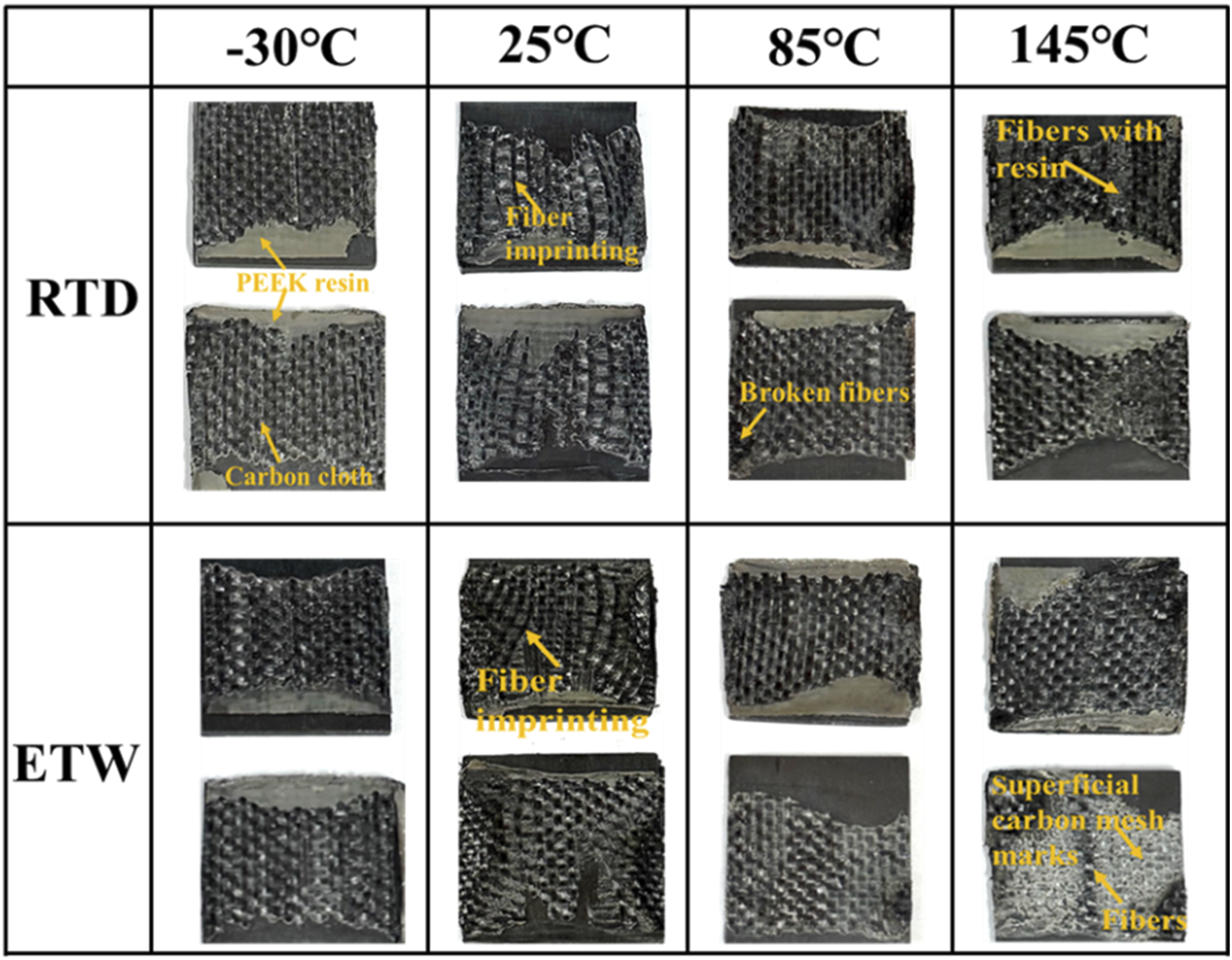
SEM Images
Figure 12 exhibits the SEM images of the fracture surface of the joints of the specimens without aging treatment at the test temperatures of −30°C (a1∼a3), 25°C (b1∼b3), 85°C (c1∼c3) and 145°C (d1∼d3). During the lap shear load, cohesive failure occurred in HE (Figures 12(a1), 12(b1) and 12(c1)). Broken fibers were noted in Figure 12(a2). At higher magnification (see Figure 12(a3)), fiber pull-out marks and shear peaks between fibers were distinctly visible. The fibers were observed to be covered by a thin polymer matrix (see Figure 12(b2)) and the shear tips between fibers were obvious at higher magnification (see Figure 12(b3)), indicating the good interfacial bonding between HE and polymer matrix. Purslow also reported the similar situation in the study on shear damage in CF/PEEK composites.
34
In Greenhalgh’s study,
35
during specimen loading, the load applied to the fiber surface led to the spikes so that interlaminar shear was induced at the fiber/matrix interface. Holes in the polymer can be seen in Figure 12(d1). The fracture surface exhibited plastic deformation of the resin, thus potentially leading to the extension of the fracture surface during loading before fracture (see Figure 12(d2)). Under a large magnification (see Figure 12(d3)), a visible gap between fiber and resin suggested the inadequate adhesion between fiber and polymer probably due to interface degradation at elevated temperatures. The above phenomena indicated that, with the rise in temperature, the interfacial bonding strength between fiber and matrix decreased. A low temperature was prone to lead to brittle fracture, whereas a high temperature promoted ductile fracture. SEM images of the fracture surfaces of the welded joints after tensile shear tests at −30°C (a1-a3), 25°C (b1-b3), 85°C (c1-c3), and 145°C (d1-d3) under RTD conditions.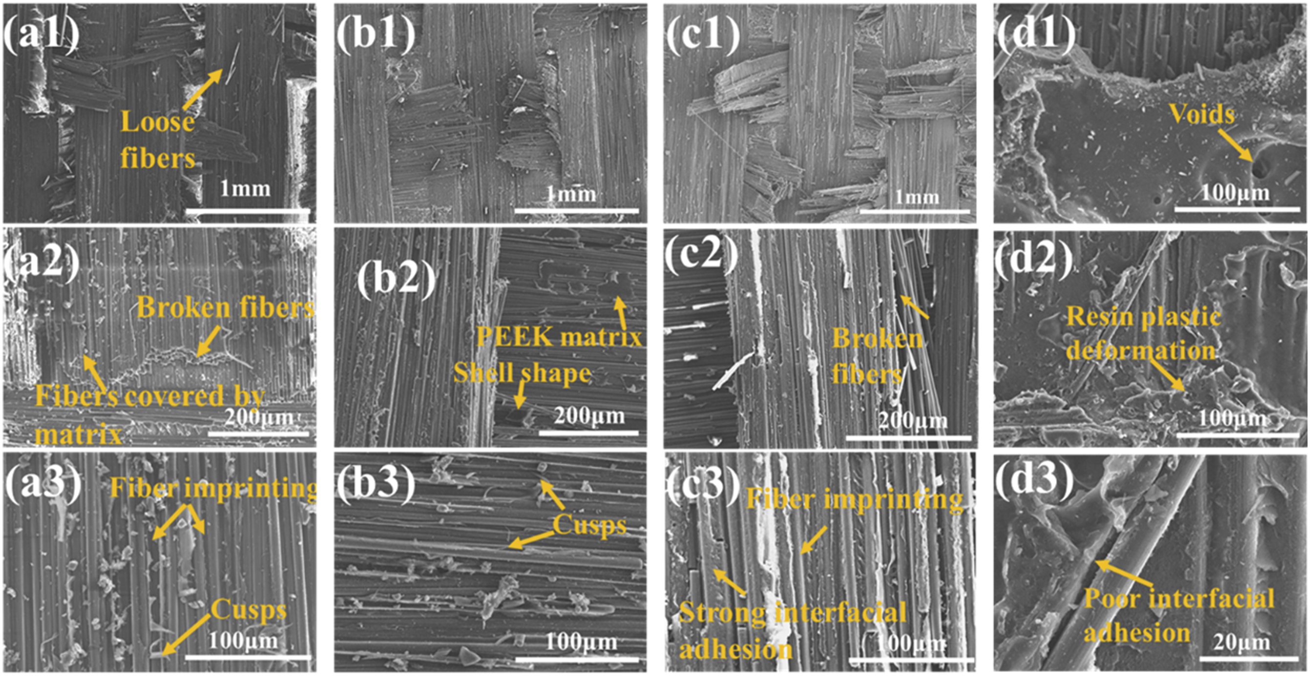
SEM images of the fracture surfaces of the joints tested at −30°C (a1 ∼ a3), 25°C (b1 ∼ b3) 85°C (c1 ∼ c3) and 145°C (d1 ∼ d3) for the specimens aged at 85°C and 90% RH are shown in Figure 13. For specimen RH-30 (see Figures 13(a1)–13(a3)), matrix wear, shear tips between fibers, fiber pull-out marks, and river patterns could be discovered. Matrix wear might be interpreted as follows. The degradation of polymer chains was caused by accelerated aging in high-temperature and high-humidity environments, resulting in the decreased mechanical properties of the matrix and the compromised bond strength between the matrix and carbon fibers. At −30°C, the overall toughness of the material decreased and the fiber pull-out phenomenon was more common, as confirmed by the brittle fracture behavior of the material. During fracture, crack expansion generated a river-like pattern on the fracture surface due to stress waves and plastic deformation at the crack tip. The fracture morphologies of specimen RH25 (see Figures 13(b1)–13(b3)) and specimen RH85 (see Figures 13(c1)–13(c3)) were similar to that of specimen RH-30. Fibers impregnated with a polymer matrix could be observed (see Figure 13(b3)), suggesting the good interfacial adhesion. This adhesion facilitated the propagation of failures near the fiber/matrix interface. Specimen RH145 (see Figures 13(d1) –13(d3)) showed loose fibers on the fracture surface (see Figure 13(d1)), plastic deformation of the resin matrix (see Figure 13(d2)), and the exposed fibers and holes (see Figure 13(d3)). At 145°C, the viscoelasticity of the PEEK matrix increased and the interfacial bond strength between fibers and matrix decreased, facilitating the detachment of fibers from the matrix during the fracture process. Furthermore, the aging treatment could further weaken the bond between fibers and matrix, thereby promoting the loosening of fibers. The exposed fiber suggested that the fiber pull-out phenomenon occurred during the fracture process due to the plastic flow of the matrix. This phenomenon was pronounced at elevated temperatures. The observed phenomena suggested the reduction in the interfacial bonding strength of the specimen after the aging treatment and the exposure to high-temperature testing conditions. SEM images of the fracture surface of the welded joints after tensile shear tests at −30°C (a1-a3), 25°C (b1-b3), 85°C (c1-c3) and 145°C (d1-d3) under ETW conditions.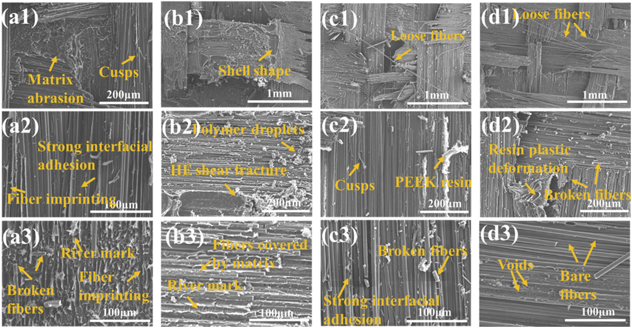
Conclusions
In this paper, the effects of different AlN content and environmental conditions on the performance of welded joints were studied, and the fracture surface of the joints was analyzed by SEM. The results are as follows: (1) The addition of modified AlN whiskers improved the tensile strength, thermal conductivity and elastic modulus of PEEK composites. Compared with CF/PEEK, the thermal conductivity of CF/AlN/PEEK increased by 23.57%. When the AlN content was 5 wt.%, the LSS of the welded joint reached 30.63 MPa, which was 41% higher than that of the welded joint without AlN addition. The strength of the welded joint before and after wet heat aging showed the same trend with the change of AlN content. (2) The dynamic mechanical properties of CF/PEEK composites were significantly affected by moisture and heat aging. The storage modulus (E′), loss modulus (E′) and glass transition temperature (Tg) of CF/PEEK composites in wet heat environment (ETW) environment were lower than those in room temperature dry environment (RTD) environment, and the loss factor (tan δ) was increased. This phenomenon indicated that water penetration leaded to plasticization of matrix and relaxation of molecular chain. (3) With the increased of test temperature, the LSS of welded joints in both RTD and ETW showed a decreasing trend. The LSS of RTD group joints decreased by 18%, and that of ETW group decreased by 27%. In the temperature range of −30°C to 145°C, the average LSS difference of the joints before and after aging treatment was only 1.9%–10.4%, which proved the excellent environmental stability of the material under extreme conditions. SEM analysis showed that the main failure mechanism of CF/PEEK resistance welded joints was HE cohesion failure, and the fracture mechanism may be determined by the reduction of interface bonding strength and the enhancement of matrix plastic deformation ability. Aging treatment may accelerate this fracture process, resulting in the failure of the material under low stress.
Footnotes
Author contributions
CH: Methodology, Visualization, Writing-original draft. SG: Investigation. RX: Formal analysis, Writing-review and editing. WW: Validation, Supervision. ZF: Validation, Supervision, Project administration. WJ: Conceptualization, Writing-review and editing, Funding acquisition.
Declaration of Conflicting Interests
The author(s) declared no potential conflicts of interest with respect to the research, authorship, and/or publication of this article.
Funding
The author(s) disclosed receipt of the following financial support for the research, authorship, and/or publication of this article: This work was supported by the National Natural Science Foundation of China (52322207, 92163208, 52332003, 52022072), the National Key Research and Development Plan of China (2021YFB3701400), the Hubei Longzhong Laboratory (2022ZZ-11) and China Minmetals Tungsten Research Program (No. 20220303).
Ethical Statement
Data Availability Statement
The data that support all plots within this paper is available from the corresponding author upon reasonable request.