
Abstract
The process-induced voids during resistance welding of glass fabric-reinforced polyetherimide was investigated. The mechanisms of void formation in adherends, in particular, the residual volatile-induced voids and the fibre de-compaction-induced voids, were analysed. Due to the non-uniform temperature and stress distributions in the joints during welding, a non-uniform void distribution was observed in the joints with more voids generated in the middle of the joints than at the edges. Welding temperature and pressure were shown to have a large influence on void formation. Increasing of welding pressure was shown to effectively reduce the voids, while the residual moisture-induced voids were found more difficult to be eliminated than the fibre de-compaction-induced voids.
Introduction
By locally melting and consolidating thermoplastics at the interface, welding has been found to be a fast and cost-effective joining method for thermoplastic composites. Among the various welding techniques, resistance welding is one of the most interesting and mature techniques. 1 –4 Being a thermal process, the quality of resistance welded joints is highly dependent on the welding parameters, 4,5 that is, welding pressure, power input and heating time. A deeper review of the welding process, including heat generation, heat transfer and crystallization kinetics, is given by Maffezzoli et al. 6 Voids, or porosities, have been found to be an issue in thermal processing of thermoplastic composites, 5,7 –9 in which reheating of composites is a necessary procedure. Voids are sometimes observed in the weld line or in the adherends of resistance welded thermoplastic composite joints. 5,10 –12 The presence of voids is shown to have an influence on the mechanical performance of the joints. 5,13,14 Therefore, understanding the mechanisms of void formation in resistance welding of thermoplastic composites is important for improving the welding process.
Resin impregnation and void reduction are key steps for manufacturing of thermoplastic composites using processes such as liquid matrix impregnation, 15,16 tow placement 17,18 and impregnation of commingled thermoplastic composite yarns. 19,20 The origin of interbundle and intrabundle voids is related to interbundle flow and intrabundle flow, respectively, and a study of two-scale impregnation is performed by Gennaro et al. 19 Welding of thermoplastic composites, however, is secondary processing of fully consolidated laminates, and there are no initial interbundle or intraply voids before welding. In literatures, many hypotheses have been proposed aiming to explain void generation during welding of thermoplastic composites. 5,8,10,12,21 –24 Voids were observed in the weld line of dual-polymer welded graphite-polyarylsulfone/polysulfone composites owing to trapped volatiles and overheating at the weld interface. 8 Xiao 8 developed a thermal buckling model to analyse voids and de-consolidation induced during induction heating of carbon fibre (CF)-reinforced polyetheretherketone and indicated that thermal stress induced in the non-uniform temperature fields of the parts was the cause of voids. Ageorges et al. 5 attributed voids generated in resistance welding of CF reinforced polyetherimide (PEI) to the de-consolidation of laminates subjected to an inadequate welding pressure, for example, lower than 0.2 MPa. A similar explanation was also used for void generation during resistance welding of metal–thermoplastic composites 25 and thermosetting composites-thermoplastic composites. 21 Ye et al. 23,24 proposed a ‘void growth, migration and closure’ model for thermal processing of thermoplastic composites where de-consolidation and re-consolidation were regarded as the main driving forces for void growth, migration and closure. More recently, Dubé et al. 12 attributed the process-induced voids in resistance welding of glass fibre (GF)-reinforced PEI and CF/PEI to two phenomena: (1) a reduction of pressure in the joints caused by the squeezing out of the polymer and (2) the relatively low environmental resistance of the PEI polymer. Despite all these studies, a comprehensive understanding of the mechanisms involved in void formation and void distribution in resistance welding of thermoplastic composites considering the inherent non-uniform temperature distribution in the joints is still missing.
In this study, both a theoretical analysis and an experimental investigation were performed to better understand void formation in adherends during resistance welding of GF/PEI composites. In order to narrow down the possible causes of void formation to investigate in this study, preliminary thermomechanical analysis (TMA) tests were performed on ambient conditioned neat PEI specimens (with residual moisture) and GF/PEI composites specimens (without residual volatiles). Voids were found in both specimens after a thermal cycle with a plateau temperature of 300°C (the glass transition temperature of PEI is 215°C 26 ). Since there was no resin flow or severe temperature gradients in the specimens, the voids cannot be caused by resin squeeze flow or thermal buckling. Residual moisture and fibre de-compaction were thought to be the most likely causes of voids in these PEI and GF/PEI specimens, respectively. Therefore, the focus of this study was set on voids induced by residual volatiles and fibre de-compaction.
Experimental
Materials
The adherends used for welding were made of eight layers of 8HS woven GF/PEI prepregs, supplied by TenCate, the Netherlands. The GF/PEI laminates, with a stacking sequence of [(0/90)]4s, were consolidated in a hot platen press at a processing temperature of 320°C and a consolidation pressure of 2.0 MPa for 20 min. The obtained laminates had a resin volume fraction of around 50%. Adherend plates of 192 × 50 mm2 were cut from the large laminates using a water-cooled diamond saw. A plain woven metal mesh made of AISI 304 L stainless steel (Belleville Wire Cloth Co., Inc, 18 Rutgers Avenue, Cedar Grove, NJ 07009, USA), with a wire diameter of 0.04 mm and gap of 0.09 mm, was used as the heating element. Mesh strips of 250 × 13 mm2 were cut from larger sheets of metal mesh and used as the heating elements for the resistance welding. To provide a resin rich area at the welding interface, the mesh was sandwiched between two layers of 60 µm-thick PEI resin films prior to the welding process.
Welding process
An in-house developed resistance welding set-up 14 was used to weld the joints. The welding energy was provided by a computer-controlled power supply unit, with a maximum DC output of 45 A and 70 V, from Delta Elektronika (Vissersdijk 4, 4301 ND Zierikzee, the Netherlands). The resistance welding process was controlled by a labview program (product of National Instruments. The version of Labview used in this work is LabVIEW 2010). The welding parameters, that is, current, voltage and temperature, were recorded during the welding process using a data acquisition system. The clamping pressure and welding pressure were applied using two separate pneumatic systems. High-density fibre wood blocks were used as the thermal insulators. Predefined appropriate welding parameters, that is, 80 kW/m2 for the power input and 55 s for the heating time, 14 were used to weld all the joints.
Measurement of void content
The void distributions of the joints were inspected using Zeiss Axiovert 40 MAT optical microscope (Carl Zeiss B.V. Trapezium 300, 3364 DL, Sliedrecht, Nederland) at a magnification of 2.5×. The middle parts of the joints were used to rule out possible ‘edge effects’, such as too high or too low temperatures near the edges. The specimens were cut-off, embedded in an epoxy resin (Tecnovit® 4071) (Heraeus Kulzer GmbH, Philipp-Reis-Strasse 8/13, 61273 Wehrheim, Germany), polished and observed. Grey-scale images were captured for the cross-sections of the joints, and then these images were used for quantitative analysis. The void content of the cross-sections was calculated using digital image processing procedures, including image trimming, image filtering, image binaryzation and pixel statistics.
Measurement of residual volatiles
When exposed to an open environment, PEI tends to absorb moisture from the surroundings until it reaches a saturation state. Additionally, residual N-methyl-2-pyrrolidone (NMP), a solvent used in fabrication of GF/PEI prepreg, is usually present in the GF/PEI pregregs as received. The boiling temperature of NMP in atmosphere is 204.3°C. 27 The contents of residual moisture and NMP in the GF/PEI composites were measured using drying tests. To measure the weight fraction of residual NMP in GF/PEI, the prepreg was put in an oven at 135°C for 12 h to prevent the possible influence of residual moisture, and then it was dried at 260°C for 3 h. The fraction of residual NMP was calculated by weighing the prepreg before and after the final drying process. Since GF/PEI laminates can also absorb moisture from their surroundings after fabrication, the weight fraction of residual moisture in the laminates was measured in a similar way: drying the laminates in an oven at 135°C until a steady weight was achieved and measuring the weight before and after the final drying process.
Analysis
Thermal and stress analysis
As a typical non-isothermal process, resistance welding of thermoplastic composites usually results in non-uniform temperature distributions in the joints both along the weld line and in the through-the-thickness direction. 28 As the stiffness of a thermoplastic matrix is highly dependent on the welding temperature, the distribution of welding pressure (or internal stress) in the joints could also be non-uniform, which in turn would influence void generation and void distribution inside the joints. Therefore, to analyse the void formation and distribution in resistance welding, the thermal behaviour and stress distributions of the joints should be determined first.
A two-dimensional (2-D) heat transfer model, as shown in Figure 1(a), was developed using COMSOL Multiphysics® 4.3b to simulate the temperature distribution of joints in resistance welding. The welding energy was provided by Joule heating of the metal mesh heating element. The governing equation of heat transfer is
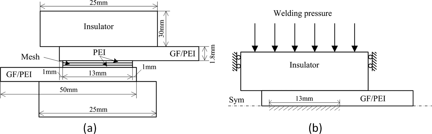
The geometry and boundary conditions of resistance welding for heat transfer analysis (a) and internal stress analysis (b).

where ρ is the density, Cp
is the heat capacity,
The relevant material properties are listed in Table 1. Temperature-dependent material properties were used for GF/PEI laminates and PEI film, as listed in Table 2. The material properties for the PEI resin were provided by the supplier, and the temperature-dependent specific heat of GF/PEI was measured using differential scanning calorimetry (DSC) tests according to ASTME1269-11 standard. The temperature-dependent thermal conductivity of GF/PEI laminates was measured in the laboratories of the Koninklijke DSM N.V. (the Netherlands) using the laser flash method.
Material properties at room temperature for heat transfer model.
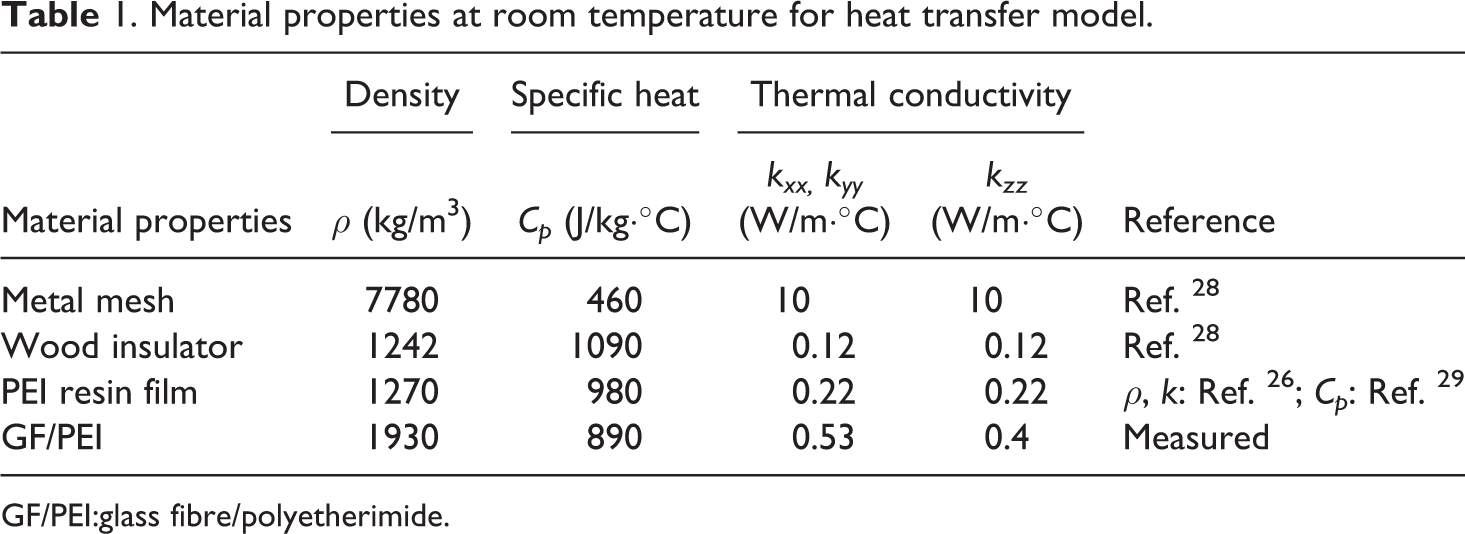
GF/PEI:glass fibre/polyetherimide.
Temperature dependent material properties of GF/PEI and PEI.
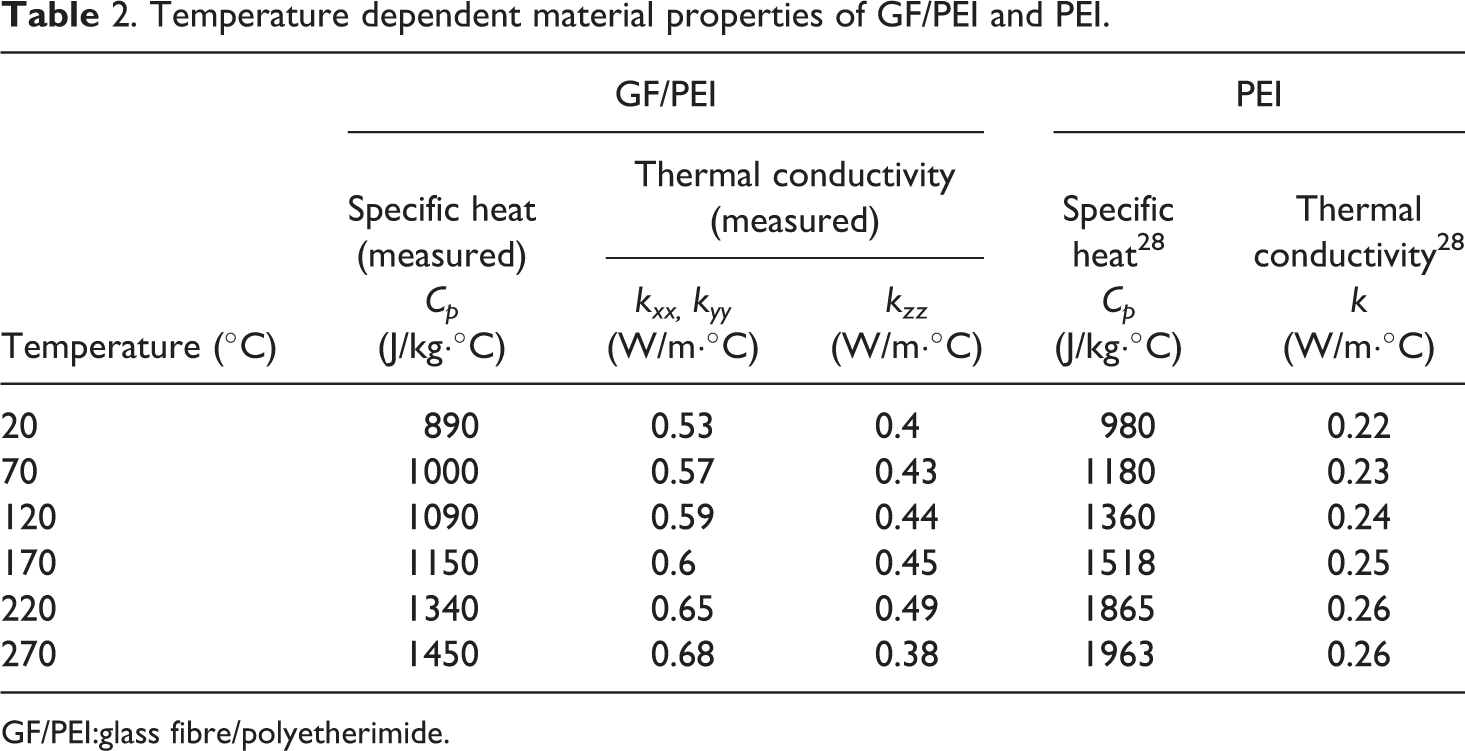
GF/PEI:glass fibre/polyetherimide.
The boundaries of the heat transfer model were set to be free convection with surface-ambient radiation as described in:

where the free convection coefficient
Stress analysis was also performed in COMSOL Multiphysics® 4.3b, and the heat transfer model was coupled with the structural analysis model to predict the inner stresses of the joints during welding. Several assumptions were made in the structural analysis model: (1) the inner stress was analysed using a cross-section 2-D plane strain model by assuming that the length of the joints (192 mm) is much higher than the overlap width (12.7 mm) and there is no strain along the longitudinal direction; (2) due to much smaller thickness of the metal mesh heating element as compared to the composites, the weld line was not considered in the model; (3) due to the symmetry in geometry, only half of the model was used for the stress analysis; (4) thermal expansion was not considered in the model because the effect of thermal expansion should be much smaller than the effect of modulus change with increasing temperature during welding, so this should not have a significant impact in the results. The geometry and boundary conditions of the model are illustrated in Figure 1(b), where the weld overlap area is defined as a fixed wall and a constant welding pressure uniformly applied to the top of the insulator. The mesh consists of triangular elements with quadratic shape functions, and the total number of elements is 2124. The relevant material properties at room temperature are listed in Table 3.
Material properties at room temperature for stress analysis.
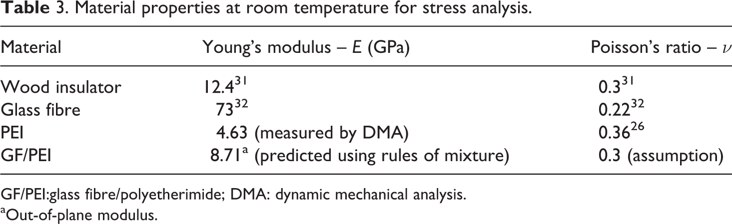
GF/PEI:glass fibre/polyetherimide; DMA: dynamic mechanical analysis.
aOut-of-plane modulus.
Since mostly compressive loads are applied during the welding process, compressive stress should be the dominating stress in the joints. To simplify the problem, the GF/PEI laminate was assumed to be isotropic and a temperature-dependent out-of-plane modulus was used. The temperature-dependent out-of-plane modulus of GF/PEI (E c) was approximately predicted from the modulus of fibre and polymer using the rule of mixtures33:
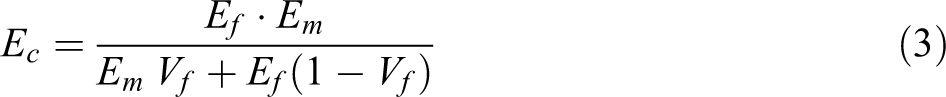
where E f is the modulus of the fibre and E m is the modulus of the matrix. E f was assumed to be constant during the welding process, while the temperature-dependent E m was measured using dynamic mechanical analysis (DMA) and rheology. The DMA tests were performed from T room to 240°C with a heating rate of 2.5°C min−1 using a frequency sweep of 0.1–100 Hz. As the shear rate of the matrix was believed to be low in resistance welding, the results measured with a frequency of 0.1 Hz were used. For high temperature (T > 240°C), rheology measurements were performed and E′ (tensile storage modulus) was calculated from G′ (shear storage modulus) using an assumed constant Poisson’s ratio of 0.3. The calculated GF/PEI modulus are listed in Table 4.
Temperature dependent modulus of GF/PEI in the through-the-thickness direction.
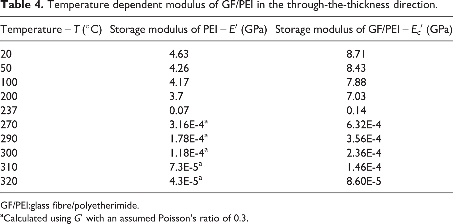
GF/PEI:glass fibre/polyetherimide.
aCalculated using G′ with an assumed Poisson’s ratio of 0.3.
Void formation due to fibre de-compaction
Since normally a relatively high consolidation pressure, 2.0 MPa for this study, is used for fabrication of thermoplastic composites, residual compression stresses could be stored in the consolidated laminates, especially for glass mat or woven fabric-reinforced composites. 34 –36 If the consolidated laminates are reheated, the residual compression stress previously stored in the fabric might be released due to the reduction of matrix stiffness at elevated temperatures. Such a process is usually referred to as fibre de-compaction. 23 Several studies have been performed on the fibre de-compaction-induced voids, 7,37 and in these studies, a representative volume element (RVE) analysis is used by assuming a homogeneous composite material and resin flow through the fibre preform obeying Darcy’s law. However, the voids generated during fibre de-compaction of GF/PEI were mainly concentrated in the resin rich area (see Figure 2) but not inside the yarns, so applying these assumptions in our material system could be questionable. In this study, a simple analysis based on the mechanical equilibrium of the compressed fibre, as illustrated in Figure 2, was used to describe the process of fibre de-compaction. The detailed analysis is described in the following.
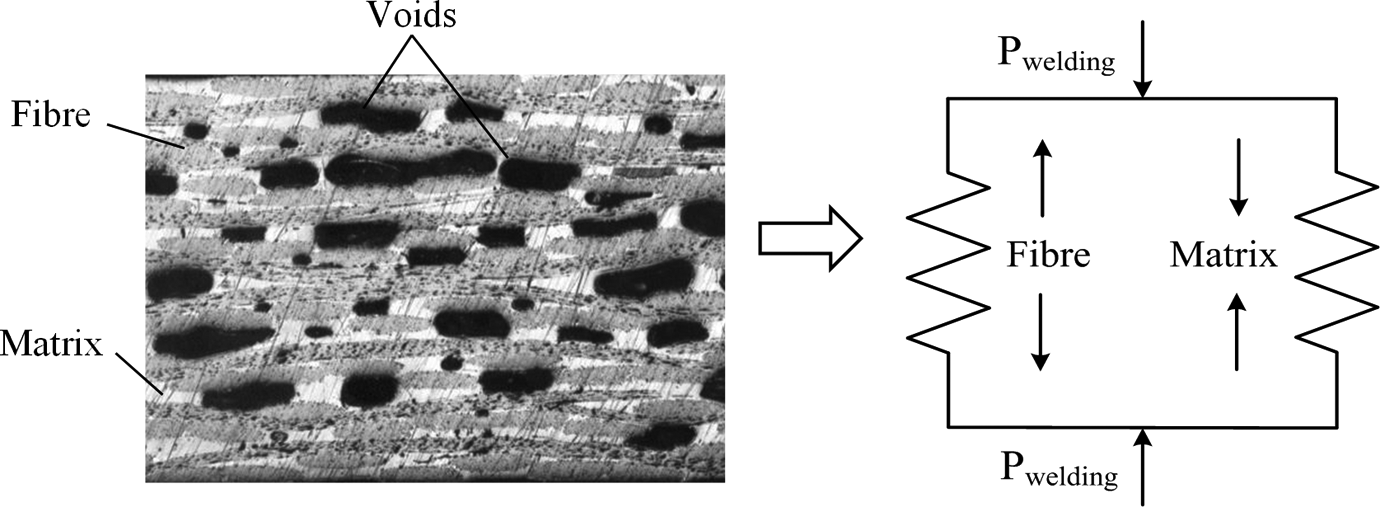
Mechanical equilibrium of the compressed fibre in a composite.
Initially, the fabric is constrained by the surrounding matrix and the applied welding pressure, where the applied welding pressure is assumed to mainly result in internal stresses in the matrix. The mechanical equilibrium can be expressed as follows:

where

where

As fibre de-compaction progresses, the laminate thickness (H) will increase, and the fibre volume fraction

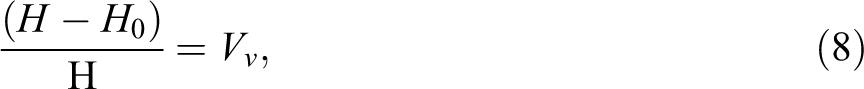
where H0 is the initial thickness of the laminate, Vf0 is the initial volume fraction of the fibre and Vv is the volume fraction of the voids. With decreasing fibre volume fraction, the residual compressive stress of the fabric will continually release until a new equilibrium is reached:

where σf is the residual compressive stress of the fabric, and it can be expressed by a power law function of fibre volume fraction
Void formation due to residual volatiles
The formation of volatile-induced voids can be expressed using classical nucleation theory. 40 –42 The distribution of residual volatiles inside the laminates is assumed to be uniform, and homogenous nucleation was used for the analysis. The effect of fibre on void nucleation is unknown, so it is neglected to simplify the problem. The formation of voids is a process of phase change, from liquid phase to gas phase, which requires excess energy to make up for the difference between the free energies of the two phases. Taking into account the changes of free volume and interfacial energies, the excess energy ΔG is equal to: 40,41

where R is the radius of the void, γ is the surface tension of polymer–void interface, Pv is the pressure inside the void and Pp is the pressure of the surrounding polymer as a result of the welding pressure.
The critical radius of the void
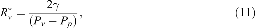

The critical void radius varies with the vapour pressure and the polymer pressure. The void nucleation rate J can be expressed by: 41,42

where N is the number of molecules per unit volume of the volatile phase, m is the mass of a gas molecule, kb is the Boltzmann constant (1.38 × 10⁻²³) and T is the absolute temperature. As void nucleation in the polymer can be assumed to occur instantaneously 43 and the rate of nucleation is proportional to the equilibrium number of critical size voids, 42 the probability of void nucleation can be calculated using the nucleation rate for any given spatial location and heating history.
After nucleation, the growth of voids in polymer can be assumed to be an ideal spherical bubble growing in a Newtonian fluid, 17,44 and RVE analysis can be used. The governing equation for void growth is given by: 17

where μ is the viscosity of the polymer, R is the radius of the void and S is the radius of the polymer shell. The polymer is assumed to be incompressible, and then the mass conservation of polymer yields:

According to the idea gas law, Pv can be calculated by the equation:
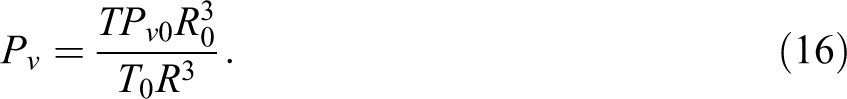
Substituting equations (14) and (15) into equation (13) yields:

Using this governing equation, the volume change of voids can be calculated.
Results and discussion
Temperature and stress distributions
The temperature distribution of GF/PEI joints during resistance welding was simulated and shown in Figure 3(a). Due to heat dissipation from the metal mesh to the surroundings, temperature gradients were observed in the through-the-thickness direction and along the weld overlap. The highest temperatures were found near the weld overlap, and similar temperature distributions are also found in the literature. 28,45
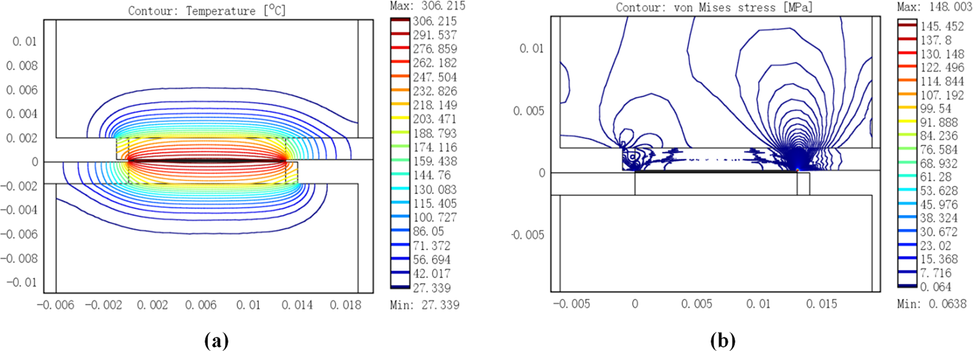
The temperature distributions (a) and stress distributions (b) of resistance welding of GF/PEI, t = 55 s. GF/PEI:glass fibre/polyetherimide.
Due to the non-uniform temperature distribution, the welding pressure will be redistributed inside the joints. Figure 3(b) shows the stress distributions of GF/PEI joints under a welding pressure of 0.8 MPa. Non-uniform stress distributions were observed with stress concentrations near the edges of the weld overlap. The much lower internal stress in the middle of the joints relative to the edges was caused by the dramatic drop of the modulus of PEI resulting from the much higher welding temperature. The non-smooth stress gradient in the joints was caused by the non-continuity of the modulus of laminates subjected to the temperature gradient (the modulus of PEI changes several orders of magnitudes from room temperature to melting temperature).
Fibre de-compaction-induced voids
The compressibility of glass fabric used in the laminates was characterized by a compression test. Eight layers of 7781 glass fabric 50 × 50 mm2 were stacked and compressed in a Zwick 20KN machine (Zwick GmbH & Co. KG, August-Nagel-Str. 11, D-89079 Ulm, Germany) using a constant cross head speed of 0.05 mm min−1. The thickness of the fabric assembly (H) can be converted into fibre volume fraction
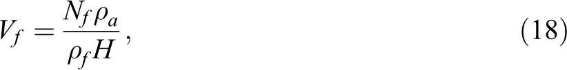
where Nf is the number of the fabric assembly been compressed, ρa is the surface density of the fabric and ρf is the density of glass fibre. In this study,
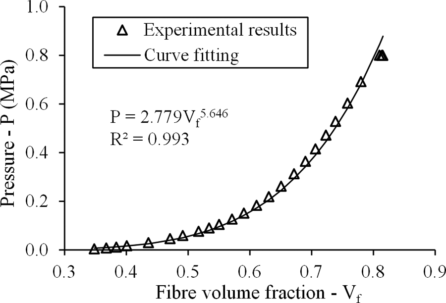
Compressibility of eight layers assembly of 7781 glass fabric.
Due to the non-uniform temperature distribution inside the joints, the distribution of
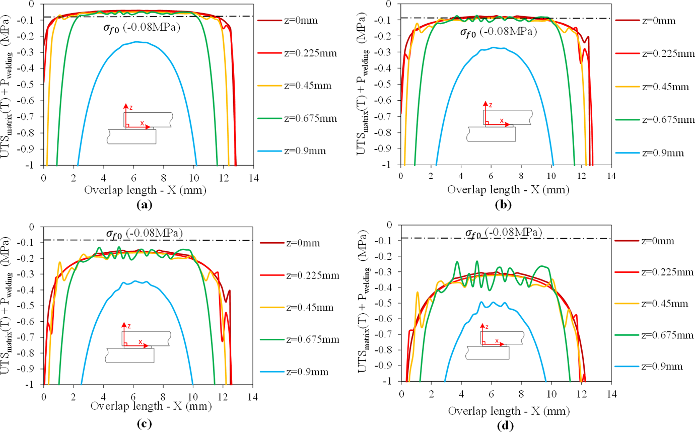
Distributions of critical stress for the GF/PEI joints welded with different pressures of 0.1, 0.2, 0.4 and 0.8 MPa (the negative sign in the plots indicates a compressive stress). GF/PEI:glass fibre/polyetherimide.
An experimental study of fibre de-compaction-induced voids in resistance welding of GF/PEI was performed. In order to prevent the possible influence of residual volatiles, the GF/PEI prepreg was dried in an oven at 260°C for 3 h before consolidation. After consolidation, the laminates were immediately welded or stored in a desiccator before welding. The GF/PEI joints were welded at four different welding pressures of 0.1, 0.2, 0.4 and 0.8 MPa. The cross-section microscopy images of the joints and the void distributions along the welding overlaps are plotted in Figure 6. Non-uniform void distributions were observed inside the joints, with more voids concentrated near the middle part of the joints than the edges, showing agreement with the model prediction. Void content was found to decrease with increasing welding pressure. A considerable void content, that is, higher than 1%, was obtained for the joints welded using a welding pressure of 0.2 or 0.1 MPa, while a relatively small void content, less than 0.1%, was obtained for the joints welded with a welding pressure higher than 0.4 MPa. A welding pressure of around 0.4 MPa was found to be the critical welding pressure for preventing fibre de-compaction-induced voids, in accordance with the model prediction.
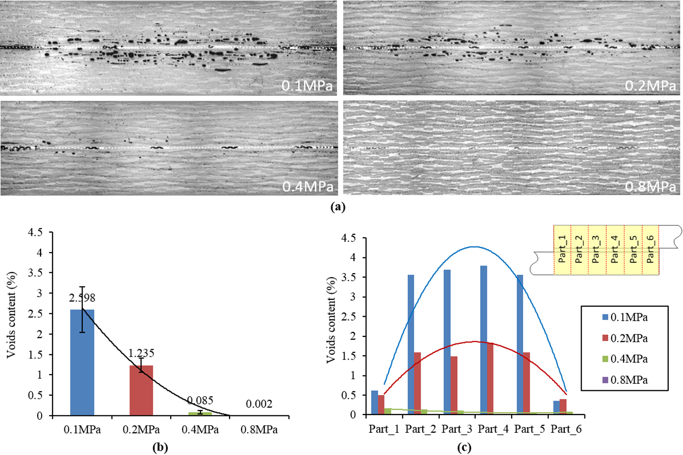
The cross-section micrograph (a), average void content (b) and void distribution (c) of GF/PEI joints welded with different pressure of 0.1, 0.2, 0.4 and 0.8 MPa. GF/PEI:glass fibre/polyetherimide.
Residual volatile-induced voids
The effect of residual volatile of laminates on void formation during resistance welding process was qualitatively studied. The generation of moisture-induced voids was studied as an example. The polymer pressure (P p) was calculated from the redistributed welding pressure in the composites (P welding) assuming that the welding pressure mainly results in internal stresses in the polymer and that the interaction between fabric and polymer can be ignored. To theoretically predict the influence of welding temperature and welding pressure on void nucleation and growth, the variables listed in Table 5 were used. Arbitrary values were used for R 0, S 0 and t, because, even though R 0, S 0 and t influence the void growth rate, 43,47 the trends will remain unchanged. Temperature-dependent water vapour pressure was used. 27 As shown in Figure 7, either a higher welding temperature or a lower welding pressure was found to accelerate void formation, that is, yielding a higher nucleation rate and faster void growth. Due to the non-uniform distributions of temperature and welding pressure inside the joints, uneven void nucleation and void growth were found inside the joints (see Figure 8). Higher void nucleation rates and faster void growths were obtained near the middle of the weld overlap than close to the edges, which were due to the higher welding temperature 28 and lower welding pressure towards the middle of the joints. Therefore, the areas in the middle parts of the joints and close to the welding interface were found to be the areas more prone to void formation.
Constants used for the analysis of moisture-induced void nucleation and growth.
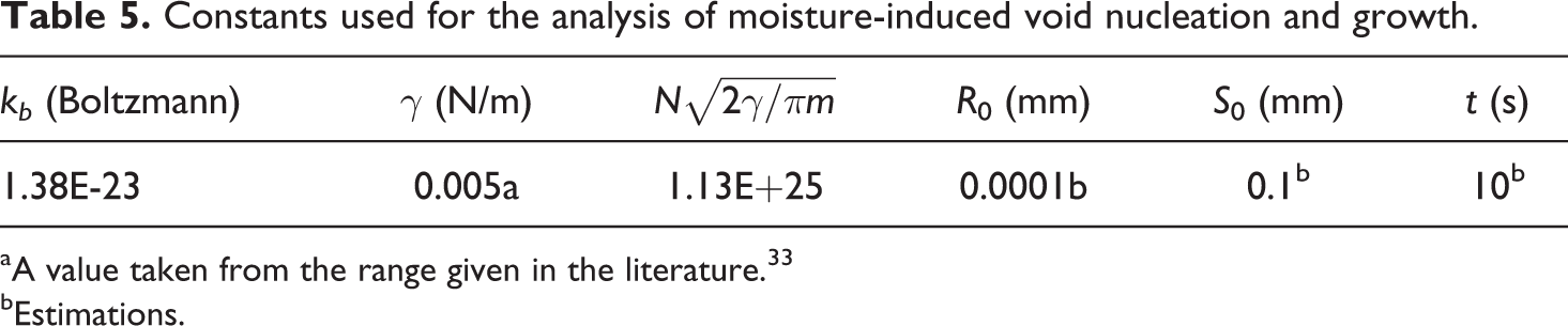
aA value taken from the range given in the literature. 33
bEstimations.
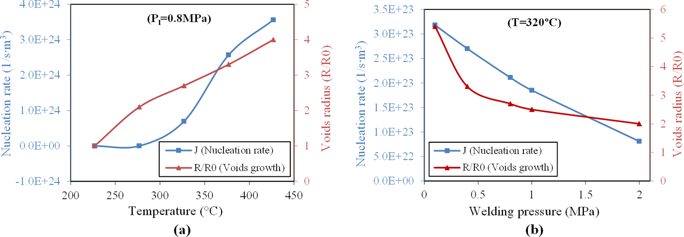
Effects of temperature (a) and welding pressure (b) on void nucleation and growth.
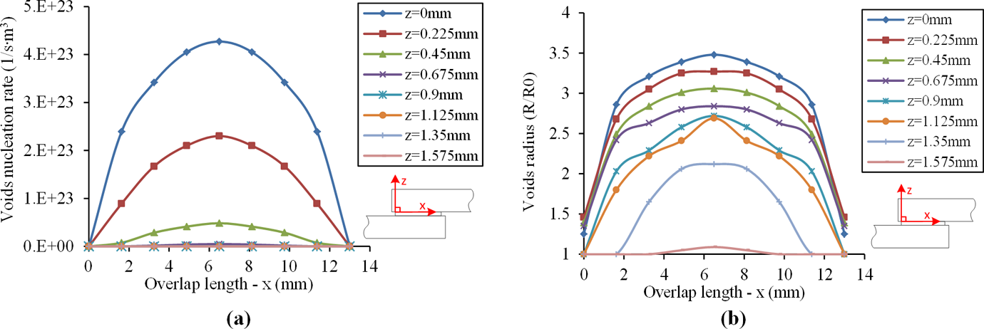
Distributions of void nucleation rate (a) and void growth (b) inside the joints for the maximum welding temperature, t = 55 s.
Experiments were performed to investigate the effect of residual volatiles, namely moisture and NMP, on void generation in resistance welding of GF/PEI joints. The average weight content of residual moisture and NMP measured in the openly stored GF/PEI laminates (stored in an ambient environment with around 50% humidity) were around 1.1 wt% and 0.3 wt%, respectively. In order to investigate separately the effects of NMP and moisture on the void formation in resistance welding, four different types of GF/PEI laminates were used and welded, as listed in Table 6. There was both residual moisture and NMP in type-A laminates; only residual NMP in type-B laminates; no residual volatile in type-C laminates; and only residual moisture in type-D laminates.
GF/PEI laminates with different drying conditions.
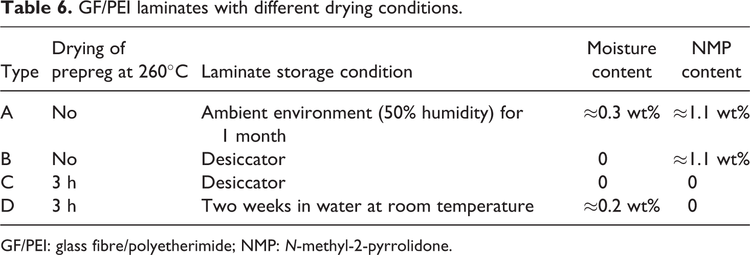
GF/PEI: glass fibre/polyetherimide; NMP: N-methyl-2-pyrrolidone.
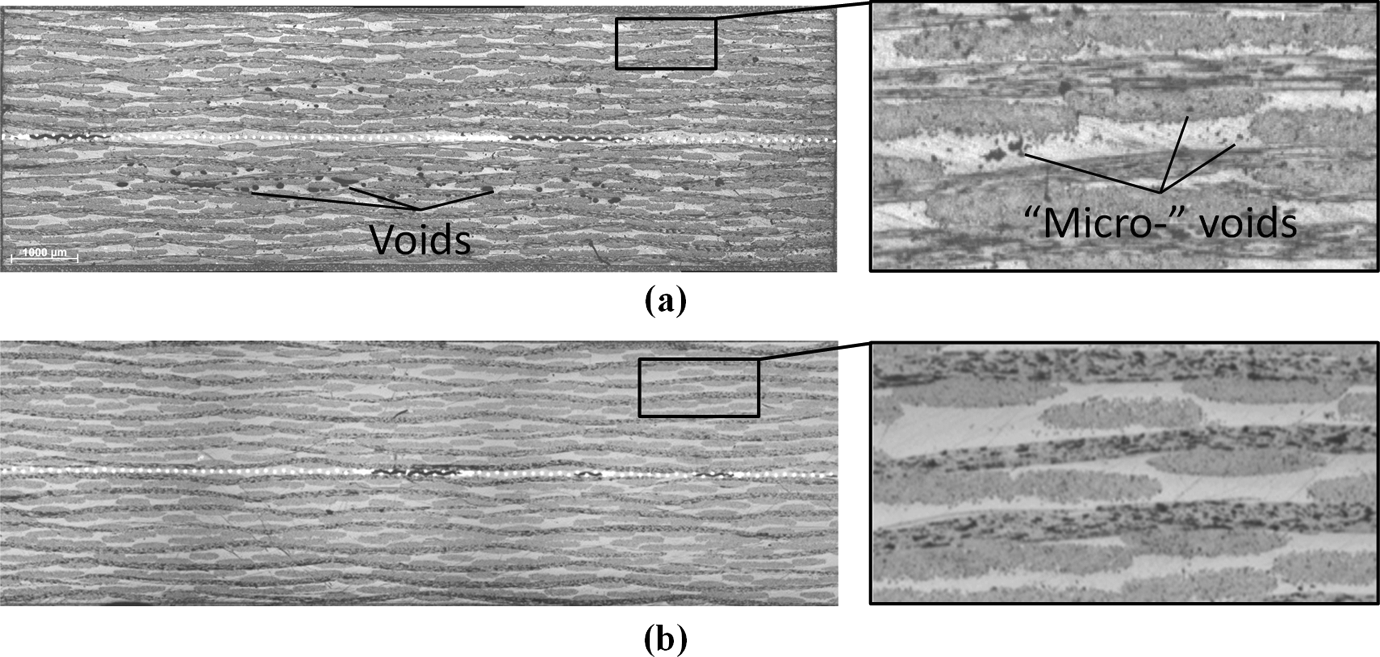
As shown in Figure 9, almost no voids were observed in type-B and type-C joints, however, a considerable number of voids was found in type-A and type-D joints. It can be deduced that the residual moisture, other than the residual NMP, acts as the main cause of volatile-induced voids in resistance welding. This should be related to the much higher vapour pressure seen for moisture with respect to NMP, 27 for example, the vapour pressures of NMP and moisture at 320°C are 0.08 and 11.3 MPa, respectively. According to the classical nucleation theory, the pressure difference between the gas state and the liquid state of a volatile is vital for void nucleation. Therefore, nucleation of NMP was found to be more difficult than nucleation of moisture under a welding pressure of 0.8 MPa. Voids were found to preferentially concentrate in the middle area of the joints rather than at the edges, showing a reasonable agreement with the results of the theoretical analysis. However, in contrast to the model prediction, the highest void density was not found near the welding interface but inside the laminates. This might be explained by the migration of voids after formation, that is, re-consolidation or void closure as proposed by Lu et al. 24
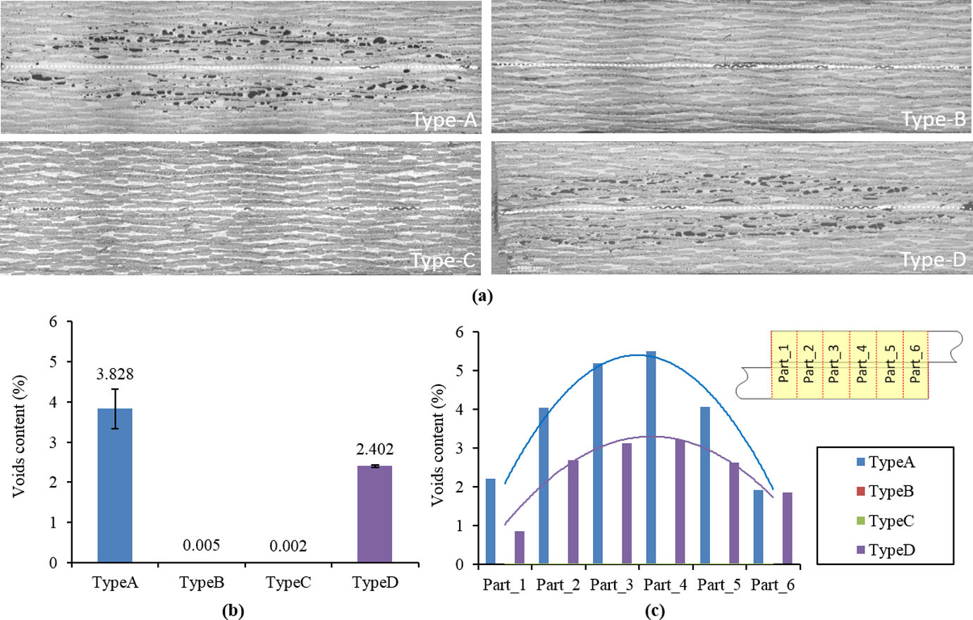
The cross-section micrograph (a), average void content (b) and void distribution (c) of GF/PEI joints using laminates in different drying conditions: type-A, type-B, type-C and type-D. GF/PEI: glass fibre/polyetherimide.
As the residual moisture in the laminates was found to be crucial for void generation, experiments were performed to study whether drying the laminates prior to welding could be a practical way to remove the residual moisture for the ambient stored laminates, such as type-A laminates. Before welding, type-A GF/PEI laminates were dried in an oven at 135°C until a stable weight was reached. Compared to the joints welded with non-dried type-A laminates (Figure 9), much less voids were found in the joints welded with dried type-A laminates (Figure 10(a)). However, unlike the type-B laminates (Figure 10(b)), some voids were still found in the oven-dried type-A laminates after welding, which could be due to the imperfection of moisture removing process. Moreover, micro-voids were widely observed in the dried laminates (Figure 10(a)), and they were probably not a consequence of welding but of the drying process.
Cross-section micrographs of resistance welded joints using oven-dried type-A (a) and type-B (b) GF/PEI laminates. GF/PEI: glass fibre/polyetherimide.
The effect of welding pressure on the residual volatiles-induced voids was also investigated. Type-A GF/PEI laminates, with both residual moisture and NMP in the laminates, were welded at different welding pressures of 0.8, 1.0, 1.2 and 1.5 MPa. The void distributions and void contents inside the joints are shown in Figure 11. Void content was found to decrease with the welding pressure, in accordance with the model prediction. A welding pressure of 1.5 MPa was found to be sufficient to reduce the voids content to a relatively low level of around 0.1%. Even though a higher pressure might help further reduce the void content, a too high welding pressure could lead to side effects, such as excess resin flow and vacuum cavities at the weld line, which might have a negative effect on the strength of the joints. 12
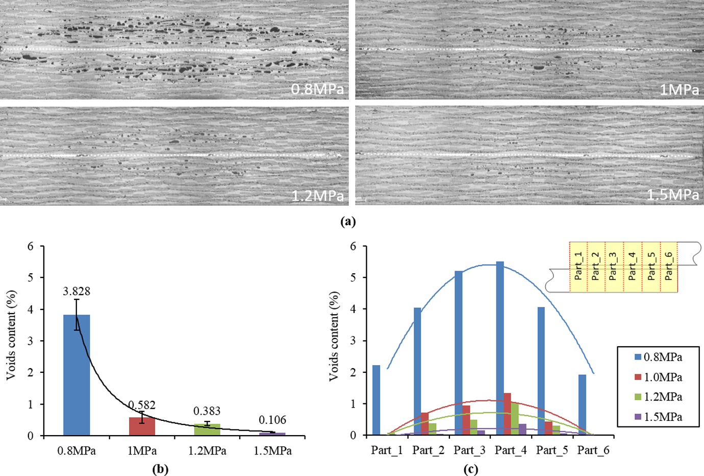
The cross-section micrograph (a), average void content (b) and void distribution (c) of type-A GF/PEI joints welded with different pressures of 0.8, 1, 1.2 and 1.5 MPa. GF/PEI:glass fibre/polyetherimide.
Conclusion
The process-induced voids during resistance welding of thermoplastic composites, in particular the residual volatile-induced voids and fabric de-compaction-induced voids in the adherends, were investigated. A combination of model simulation and experimental analysis was performed to better understand the mechanisms influencing void formation during the welding process. Resistance welding of glass fibre-reinforced polyetherimide (GF/PEI) composites was performed using a metal mesh as the heating element.
Both residual volatiles and fibre de-compaction were found to induce voids during resistance welding. Void formation was shown to be related to the welding pressure, welding temperature and the material properties of laminates, such as the matrix modulus and the fibre compressibility. Increasing welding pressure was found to help prevent the residual volatile-induced voids and the fibre de-compaction-induced voids. However, a higher welding pressure (1.5 MPa) was required to prevent the residual volatile-induced voids compared to the pressure that was required to prevent the fibre de-compaction induced voids (0.4 MPa). So, the voids induced by the residual volatiles were found to be more critical when welding under a moderate welding pressure, for example, 0.8 MPa. The residual moisture in GF/PEI laminates was found to be the main cause of the volatile-induced voids in resistance welding of GF/PEI rather than the residual solvent-NMP. Drying the laminates prior to welding was found to help reduce void generation during welding, however voids could not be completely eliminated.
Due to the non-uniform distribution of temperature in the joints during welding, the compression stress in the middle part of the joints was found to be much smaller than at the nominal welding pressure, as a result of that more voids were generated in the middle of the joints than the edges. Future work should be focused on finding strategies to improve the uniformity of internal stress distribution in joints by reducing temperature gradients along the weld overlap, that is, via tailoring/re-distributing welding energy at the weld overlap.
Footnotes
Acknowledgements
The authors would like to express their gratitude for the support provided by TenCate Advanced Composites, The Netherlands.
Declaration of conflicting interests
The author(s) declared no potential conflicts of interest with respect to the research, authorship, and/or publication of this article.
Funding
The author(s) received no financial support for the research, authorship, and/or publication of this article.