
Abstract
The possibility of assembling through welding is one of the major features of thermoplastic composites and it positively contributes to their cost-effectiveness in manufacturing. This article presents a comparative evaluation of ultrasonic, induction and resistance welding of individual carbon fibre-reinforced polyphenylene sulphide (PPS) thermoplastic composite samples that comprises an analysis of the static and dynamic mechanical behaviour of the joints as well as of the main process variables. The induction welding process as used in this research benefitted from the conductive nature of the reinforcing fibres. Hence, no susceptor was placed at the welding interface. Resistance welding used a fine-woven stainless-steel mesh as the heating element and low welding pressures and times were applied to prevent current leakage. Triangular energy directors moulded on a separate tape of PPS resin were used to concentrate ultrasonic heat at the welding interface. The static single-lap shear strength of the joints was found similar for induction and ultrasonic welding. A 15% drop in the static mechanical properties of the resistance welded joints was attributed to incomplete welded overlaps following current leakage prevention. However, the fatigue performance relative to the static one was similar for the three sorts of joints. A comparative analysis of process variables such as welding time, required power and energy was also carried out.
Keywords
Introduction
Welding is a specific assembly technique for thermoplastic composites based on the ability of thermoplastic resins to soften when heated above a certain temperature and to retain their properties after cooling down. It can be broadly defined as joining of two or more parts together by melting and consolidating (intimate contact and autohesion) under pressure of their common interface. 1,2 Welding overcomes some of the well-known issues of the traditional joining techniques for polymer composites such as stress concentration and intense labour (mechanical fastening) or extensive surface preparation and long curing cycles (adhesive bonding). Welding positively contributes to the cost-effectiveness in manufacturing of thermoplastic composites and, therefore, it is considered as one of the most attractive features of thermoplastic composites.
Welding processes are usually classified by the way in which heat is generated at the welding interface. From all the possible variety of techniques, three are usually acknowledged as the most suitable for continuous fibre-reinforced thermoplastic composites (CFRTPCs), namely, resistance, induction and ultrasonic welding. 1,3 Ultrasonic welding belongs to the group of friction welding techniques as it is based on the conversion of high-frequency and low-amplitude mechanical vibrations into heat through contact–surface and intermolecular friction. 4 Resistance welding is based on the heat generated by an electric current flowing through a resistive element sandwiched between the parts to be welded (Joule’s effect). 1,3 Induction welding relies on heating of electrically conductive (Joule and dielectric heating) and/or magnetic materials (hysteresis loses) under an alternating magnetic field. 5,6 The study presented in this article corresponds to the first step of a wider collaborative project among the Institut für Verbundwerkstoffe (Germany), the National Research Council (Canada) and the Delft University of Technology (The Netherlands). The main ambition is gaining a deeper insight into the differences among induction, resistance and ultrasonic welding of CFRTPCs from a broad approach comprising processing, weld quality and mechanical behaviour. Since none of these welding processes is believed to be the optimum for all materials and applications, 7 this study is expected to provide valuable information to help define specific areas of application as well as to further expand the current knowledge on each individual technique.
From a general perspective, several basic distinctive features can already be drawn on resistance, induction and ultrasonic welding. In what concerns the maturity level, resistance and induction welding of thermoplastic composites have already been industrially applied in the aerospace industry. 8,9 Ultrasonic welding of CFRTPCs is however much less mature, despite the fact that the same technique is very popular for industrial welding of unreinforced thermoplastics. With respect to the sorts of assemblies that can be produced, resistance welding is well suited for long and straight welding lines (one-shot welding for medium-sized welds and sequential/continuous for very long welds). 10 Induction welding potentially allows for geometrically complex welds and ultrasonic is best suited for spot welding, although sequential ultrasonic welding of larger areas could be regarded as a future option based on research results. 11 Concerning the set-up of the process, the minimum required equipment for resistance welding is the simplest one. However, induction welding does not oblige any contact with the welding stack for heating, which increases flexibility and simplifies automation. 12 Similarly, induction welding of cross-ply or woven carbon fibre (CF)-reinforced parts can be accomplished without the need of any extra material at the interface, whereas for the rest of the cases, either foreign heating agents and/or extra resin are necessary. 13,14 As for the mechanical performance of the welds, several comparative studies, often including traditional assembling procedures as well, can be found in the literature. The first ones, dating from the late 1980s and early 1990s, were mostly directed towards showing the potential of welding of CFRTPCs as well as spotting the most promising techniques. 3,7,15 –20 With some similarities with the research in this article, Beevers 21 presented in 21 a compilation of the research results of Courtlands Research, TWI and Westland Engineering (UK) on induction, resistance and ultrasonic welding, respectively, of CF polyether ether ketone (CF/PEEK) composites. A commingled high-conductivity carbon/PEEK fabric was used as the susceptor for induction welding. A stainless steel mesh and a CF/PEEK prepreg ply were the two different resistance welding implants. A Monel mesh with some additional PEEK resin was the ultrasonic energy director. Excellent welds were obtained in all the three cases with somewhat higher static strength values for the induction and resistance ones. Most recently, a comparative analysis between the static mechanical properties of induction and resistance welds in glass fibre-reinforced polyetherimide (GF/PEI) was carried out at the Delft University of Technology. 22 A stainless steel mesh was used in both the cases as the heating element or welding susceptor. The main observation was that induction welding provided stronger single-lap welds even at low welding pressures. Only scarce data are currently available regarding fatigue properties of welds. The dynamic behaviour of resistance welded joints for different materials were evaluated in previous studies. 23,24 In a comparative study of the fatigue properties of adhesively bonded, 25 induction welded and thermabonded joints was presented. In a study by Villegas et al., 26 the dynamic mechanical behaviour of resistance welded and co-consolidated joints was addressed. The main conclusion of the comparative studies is that no remarkable differences can be observed in the S-N behaviour of any of the joints under study.
CF-reinforced polyphenylene sulphide (CF/PPS), an advanced thermoplastic composite suitable for high-performance applications, was chosen for the present study. Individual single-lap samples were induction, resistance and ultrasonically welded. Despite the fact that relatively large induction and resistance welds can be produced, a decision was made to weld individual coupons in order to set solid comparison grounds with ultrasonic welding. The static as well as dynamic properties of the samples were evaluated. Cross-sections and fracture surfaces were analysed for further information on the welding process (e.g. extension of the heat affected area, heating patterns and indications on the welding temperature) and on the quality of the welds. A comparative study of some process variables such as welding and consolidation time, required power and energy was also performed. Direct comparison of thermal histories, although highly desirable, was not possible due to difficulties in accurately measuring temperatures at the welding interface for some of the welding techniques evaluated. It follows a detailed description of the experimental procedure and the research results.
Experimental
Materials
The CF/PPS composite material used in this study was supplied by Bond Laminates, Germany, as 2-mm-thick (eight layers) fully consolidated laminates (Tepex Dynalite 207-C200(8)). The CF reinforcement was 50:50 twill weave with 45% fibre volume content.
A 304-L stainless steel mesh with 0.04 mm wire diameter, 0.09 mm open gap and 0.08 mm thickness was used as the heating element for the resistance welding process. A 0.1-mm-thick neat PPS film was utilised to provide the resistance welding interface with extra resin and to manufacture energy directors for the ultrasonic welding process. The composite substrates as well as all additional materials were degreased prior to welding.
Testing and analysis procedures
The composite laminates were diamond sawed into 25.4 × 101.6 mm2 rectangular specimens that were welded in a single overlap configuration with a nominal overlap of 12.7 mm. Five samples per welding technique were tested according to ASTM D1002 in a Zwick Roell 1485 Universal Testing Machine. No tabs were applied to the samples since the grips of the testing machine could be offset in order to ensure a load path parallel to the overlap line. The apparent lap shear strength (LSS) was calculated as the ultimate load divided by the actual overlap area.
Following the procedure of similar investigations, 24 sinusoidal tension–tension fatigue tests were carried out with load ratio R of 0.1 and a frequency of 5 Hz taking the ASTM D 1002 standard as a reference in a MTS 100 kN fatigue test bench. The number of cycles to failure was registered for different load levels between 70 and 30% of the static strength. An average of 15 samples was tested per welding process. Indefinite fatigue life was defined as the ability of the welds to survive 1 million fatigue cycles. The samples that reached indefinite fatigue life were statically tested to find their residual strength.
Cross-sections and fracture surfaces were analyzed by optical microscopy (Leitz Aristomet) and scanning electron microscope (SEM; Jeol JSM-7500P Field Emission Scanning Microscope), respectively.
Welding procedures
Ultrasonic welding
A microprocessor-controlled Rinco Dynamic 3000 ultrasonic welding machine (Delft University of Technology) with maximum power of 3000 W and frequency of 20 kHz was used in this study. A cylindrical titanium horn with a diameter of 40 mm was utilised. In order to ensure accurate positioning of the composite samples and to prevent lateral shifting during ultrasonic vibration, a custom-made clamping jig was used (Figure 1). The welding jig allows for vertical movement of the upper sample, thus eliminating unwanted bending caused by melting of the energy directors during the welding process.
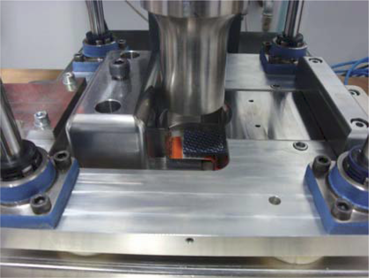
Ultrasonic welding fixture (Delft University of Technology).
Premoulded energy directors were used for preferential heating at the welding interface. In most of the studies dealing with ultrasonic welding, the energy directors are directly moulded on the surface of the composite laminates. 14,27 However, for the ease of sample preparation and to avoid an additional cycle in the processing history of the laminates, the energy directors were manufactured separately in the form of welding tapes. They consisted of a 0.2-mm-thick neat PPS strip with four 0.7-mm-high triangular energy directors (90° at the apex) moulded on top (Figure 2). The design of the welding tapes was based on previous studies, which showed that increasing the number of energy directors at the welding interface up to a certain extent enhanced the coverage of the welding area and reduced fibre disruption in the outermost layers of composite substrates. 28
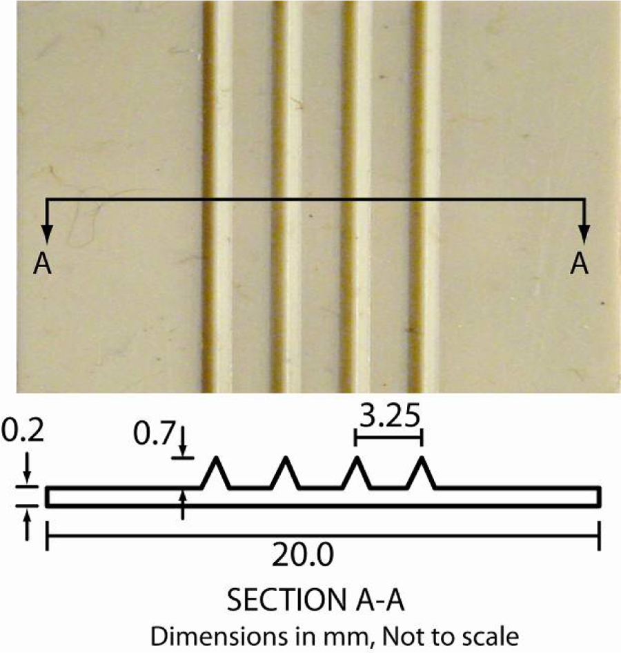
Premoulded welding tape with triangular energy directors for ultrasonic welding.
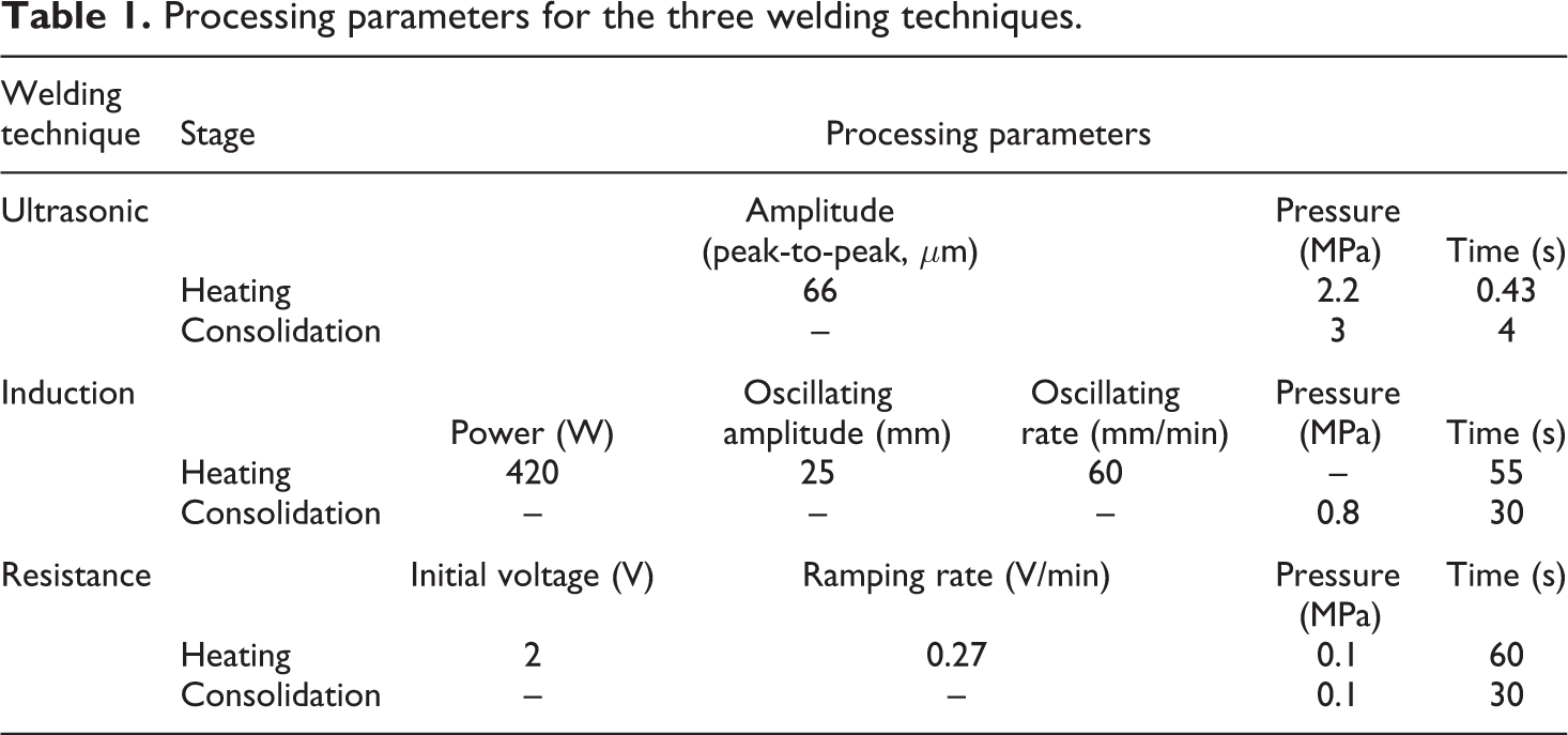
The welding tapes were manufactured in a hot platen press out of five layers of neat PPS film. The mould used for this purpose consisted of two 20-mm-thick aluminium plates. Four triangular grooves corresponding to the energy directors were machined into one of the plates, forming the female mould. After forming, sections around 26-mm-wide were cut out of the welding tape and used for welding. The welding tape was positioned on top of the bottom substrate with the energy directors transverse to the longitudinal direction of the samples. The parameters used for the ultrasonic welding process, listed in Table 1, were selected as a result of trial and error optimisation process. The main optimisation criteria were complete welded overlap and minimum deformation of the fibre bundles in the composite substrates (associated with melting of a too large volume of matrix). Direct temperature measurements at the interface proved to be difficult due to the tendency of the thermocouples to act as an energy directors and hence to heat up preferentially.
Processing parameters for the three welding techniques.
Induction welding
A custom-made induction welding machine (Institut für Verbundwerkstoffe GmbH) was used for this research work (Figure 3). It consists of a linear guide carrying a ceramic fixture, a pneumatic pressure application system, a solid-state induction power supply and a computer control unit. The induction coil and the pneumatic piston are stationary whereas the fixture can be moved translational. The induction generator works as an oscillating circuit with constant capacity and inductivity dependent on the coil. The working frequency is approximately 800 kHz and the maximum power input is 5.2 kW.
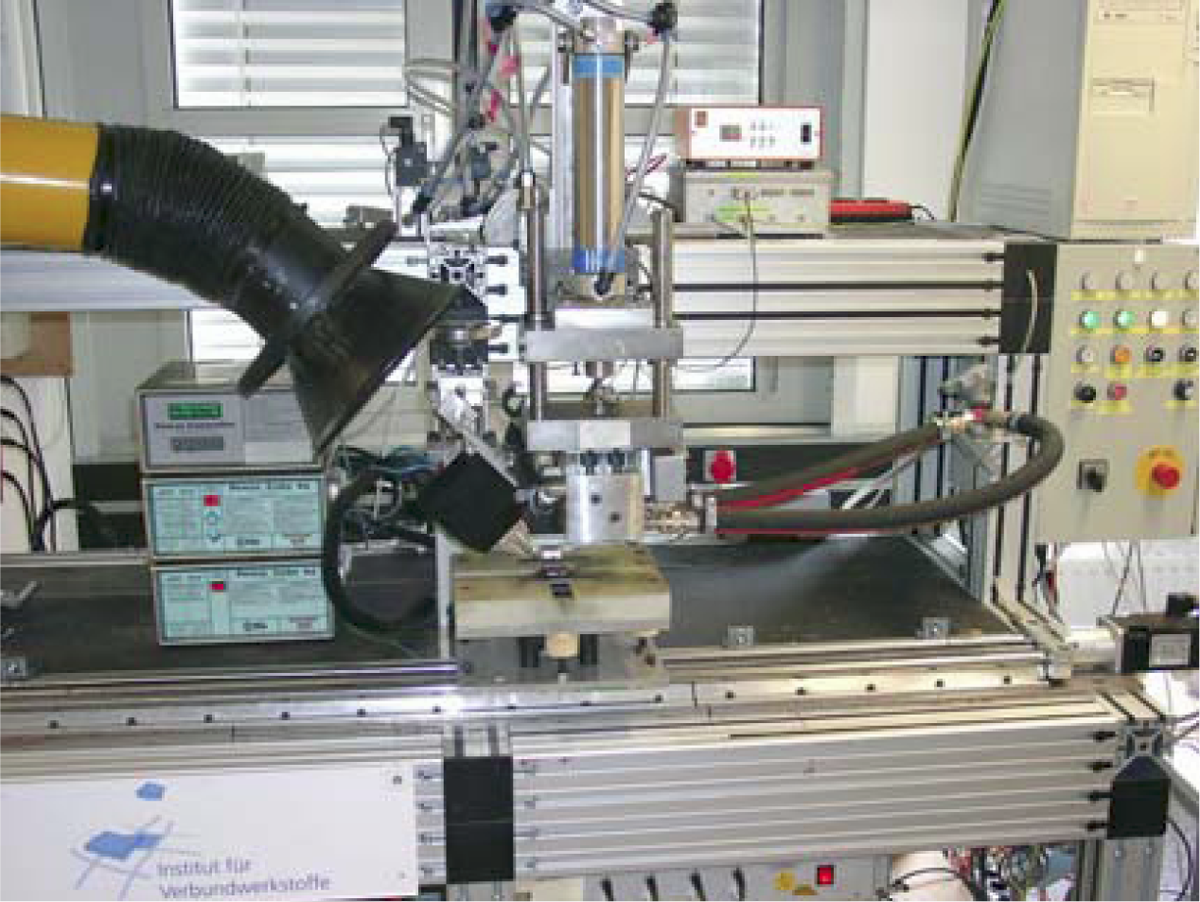
Induction welding machine (Institut für Verbundwerkstoffe).
The individual samples were oscillated under the induction coil at a certain constant rate and amplitude in order to achieve uniform heating (Figure 4). Once the processing temperature was reached, they were transported to the consolidation position and the weld was then consolidated using a die connected to a pneumatic cylinder. Neither welding susceptors nor extra resin films were used at the welding interface. Since eddy currents were induced in the carbon reinforcement, through-the-thickness heating was observed. The parameters of the induction welding process, shown in Table 1, are optimised aiming at a complete welded overlap with minimum through-the-thickness deformation of the composite substrates. No thermocouples were placed at the welding interface in order to prevent potential interferences with the magnetic field. An infrared pyrometer was used instead to measure the temperature on the composite surface closest to the induction coil.
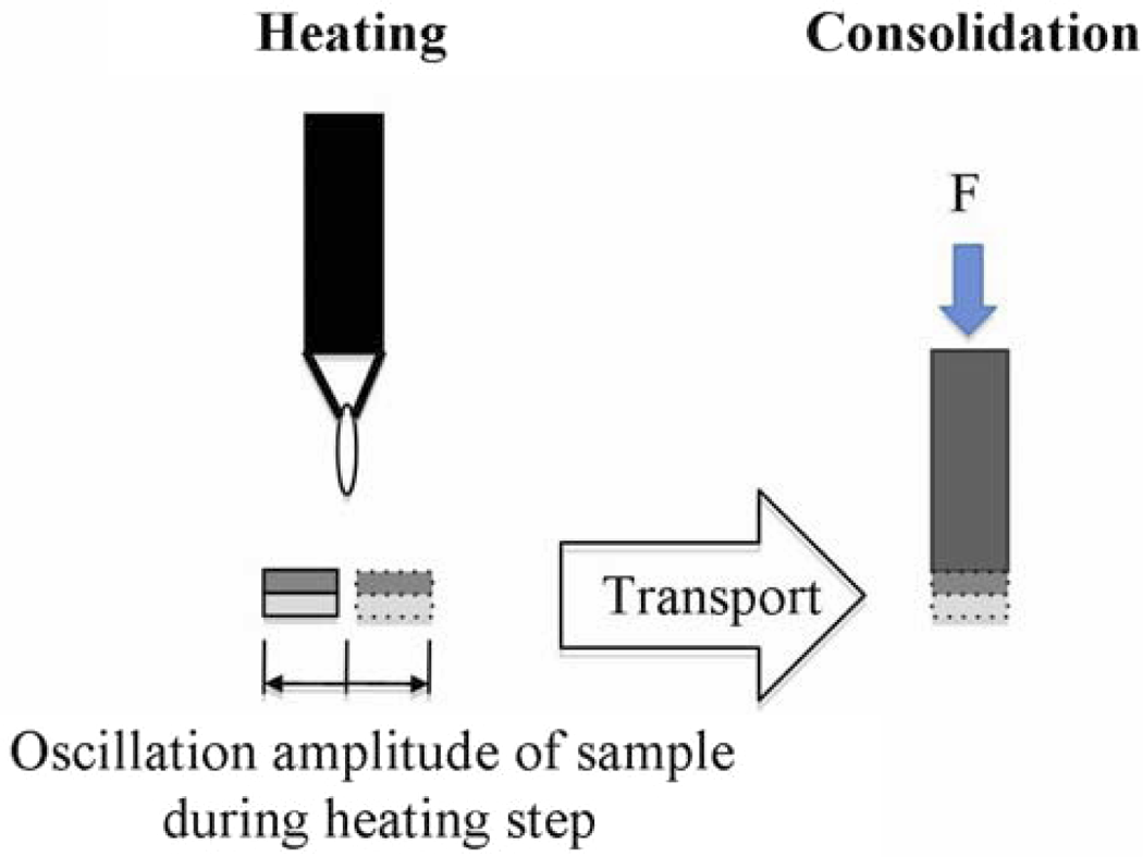
Oscillating induction heating.
Resistance welding
A custom-built resistance welding apparatus (National Research Council Canada) was used. It consists of a DC power supply unit with maximum output of 40 A and 150 V, a computer control and data acquisition system, a pneumatic cylinder and ceramic insulation blocks (Figure 5). The metal mesh heating element was sandwiched between two plies of PPS resin for electrical insulation and to create a resin-rich welding interface. The free edges of the mesh were connected to the power supply unit through copper terminals.
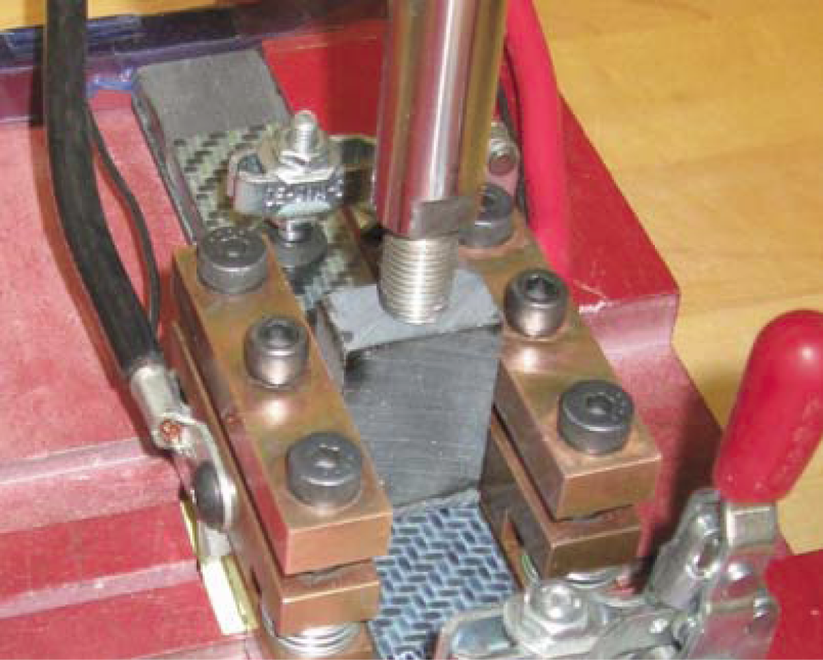
Resistance welding setup (National Research Council Canada).
In order to achieve uniform heating and to prevent thermal damage of the substrates, the electrical energy applied to the mesh was increased at a constant ramping rate. 29 The power was switched off when a processing temperature around 325°C was reached at the welding interface and the weld was allowed to cool down under pressure. The processing parameters (Table 1) were defined based on temperature readings at the welding interface (centre of the overlap) in set-up tests. Sandwiching the heating element between neat resin plies is reported to successfully prevent current from leaking from the metal wires to the carbon reinforcing fibres. 13 However, the low melt viscosity of the PPS resin imposed the use of a remarkably low welding pressure to reduce the resin squeeze-flow rate and hence to delay direct contact between metal wires and CFs. Moreover, the welding time was kept as short as possible in order to increase the robustness of the process.
Results and discussion
Visual inspection and cross-sections
Visual inspection of the induction-welded samples showed that bulk heating caused a moderate flow of resin mostly from the substrate closest to the induction coil and therefore thickness reduction, most noticeable towards the edge of the overlap. Similarly, the outer surface of that laminate lost its initial smoothness due to melting and reconsolidation of the resin. In the ultrasonic-welded samples, the outer surface of the substrate in contact with the sonotrode evidenced some surface heating next to the edge of the sonotrode indicated by a darker colour of the resin in that spot. This effect is believed to result from a slightly too stiff clamping. Moderate resin flow from the interface could also be observed in these samples. Finally, the resistance-welded samples showed no trace of the welding process on the outermost surfaces of the laminates and very little flow of resin out of the welding interface.
Representative cross-sectional micrographs of the three types of welds are depicted in Figure 6. One of the first observations is that none of them show a noticeable concentration of voids at the welding interface. However, bulk heating during induction welding leads to considerable through-the-thickness porosity in the substrates. A reduction in the thickness of one of the induction welding substrate is also evident from the cross-section. In the ultrasonic welds, some voids can be observed close to the outermost surface of the laminate. These are most probably caused by heating through surface friction with the sonotrode, which, as explained before, also leaves some slightly visible traces on the laminate. The resistance-welded samples show a satisfactorily embedded mesh and practical absence of voids.
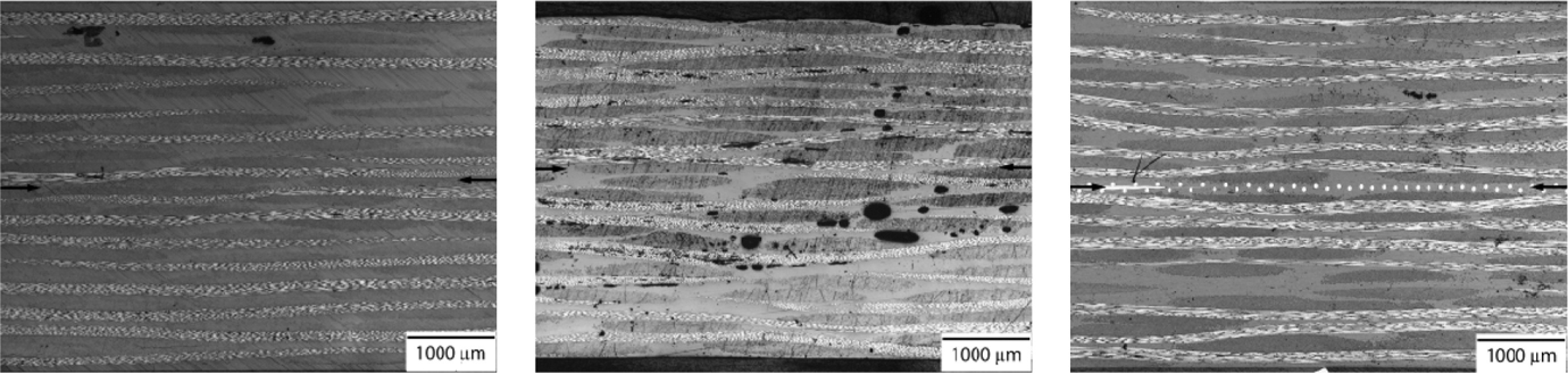
Cross-sections (centre of the overlap): ultrasonic welding (left); induction welding (middle); resistance welding (right). Arrows indicate the position of the weld line.
Static tests
Figure 7 displays the results of the single-lap shear tests. Both ultrasonic and induction welds yielded average LSS values around 27.3 MPa with very low scatter (SD below 1.5% of the average LSS values in both cases). The resistance welds had a lower strength of 23.3 MPa with a somewhat higher scatter but still below 5% of the average LSS. Direct comparison among these figures must be however done with care since basic characteristics of the welds such as presence or absence of foreign elements at the welding interface or permanent deformation of the substrates are likely to change the stress scenario at the bondline. It is well known that the peel and shear stress concentrations occurring at the edges of the overlap in single-lap shear tests are very sensitive to factors such as joint geometry (taper, fillet and bondline thickness) or the stiffness of bondline and adherends. 30,31 Consequently, the analysis of the fracture surfaces is regarded as a complementary tool to gain insight into the mechanical performance of the welds.
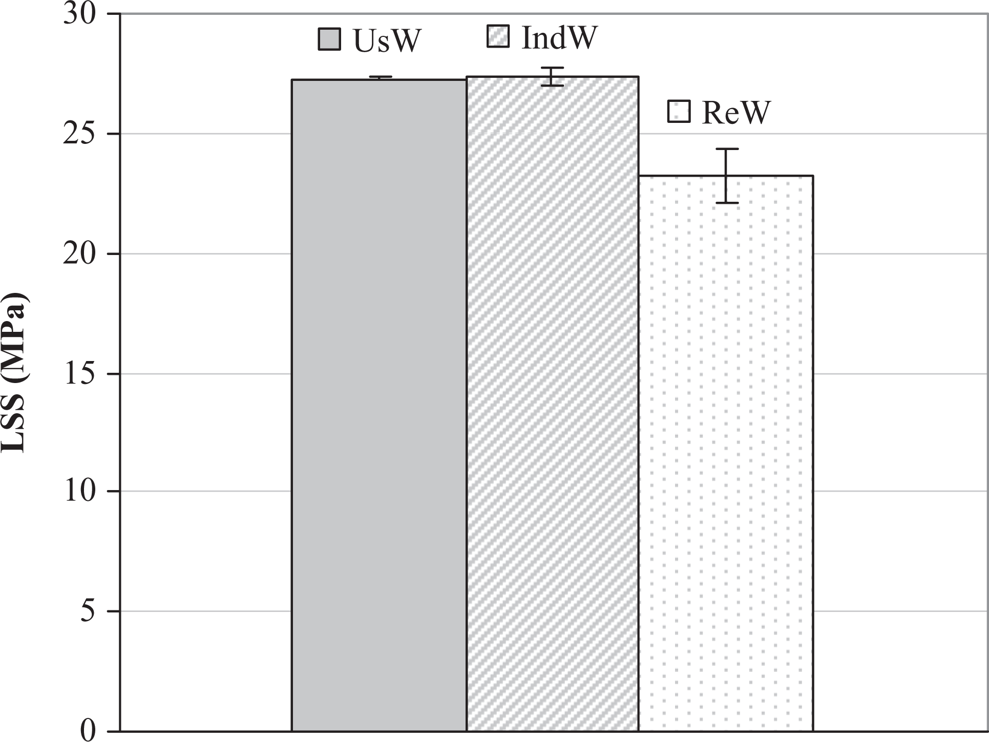
Lap shear strength results.
One of the main differences among the fracture surfaces of the three types of welds (Figure 8) is the fact that resistance-welded samples show poorly welded areas with interfacial failure 32 covering roughly 10–15% of the total area of the overlap. These are located at the edges of the overlap, where the temperatures are lower due to a more effective heat transfer from the mesh heating element to the bulk composite. 13 Attempts to either increase the welding time or temperature and hence to minimise interfacial failure yet led to current leakage, aggravated by the low melt viscosity of the PPS resin. The remaining fracture is mostly characterised by intralaminar failure and mesh tearing, which typically occurs around the centre of the overlap. Intralaminar cracks, propagating from the edge towards the centre of the overlap, leave mostly dry fibres on one of the fracture surfaces and resin together with some fibres stuck to the mesh on the opposite side indicating good consolidation of the weld.
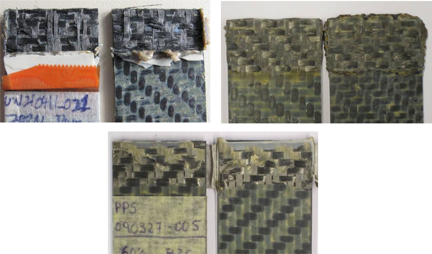
Visual inspection of fracture surfaces: ultrasonic welding (left); induction welding (right); resistance welding (middle, bottom).
Contrarily, the fracture surfaces of induction and ultrasonic welds show practical absence of nonbonded areas and overall intralaminar failure. Induction welds have a very uniform appearance, evidencing uniform temperature distribution during welding, and a moderate enlargement of the welded area caused by thermal deformation of one of the substrates. Despite the fact that no extra resin was added to the induction–welding interface, the fracture surfaces are relatively resin rich with some little porosity and broken fibres. Resin flow from the substrates is believed to provide the bondline with additional resin while welding. Visual inspection of the fracture surfaces of ultrasonic-welded samples, featuring quite a uniform appearance as well, seems to indicate primary existence of dry fibres. However, SEM micrographs (Figure 9) depict notable resin content although to a lesser extent than on the induction-welded samples. The fast cooling rates experienced by the resin at the interface during ultrasonic welding are expected to result in lower crystallinity levels and therefore a more transparent appearance of the PPS resin. Some of the ultrasonic welds show very small semicrystalline resin pockets towards the centre of the overlap covering no more than 1% of the total welded area. According to Ref. [27], they could be caused by air entrapment during the melt front propagation. Finally, some deformation of the fibre bundles caused by the ultrasonic vibration is observed as well.
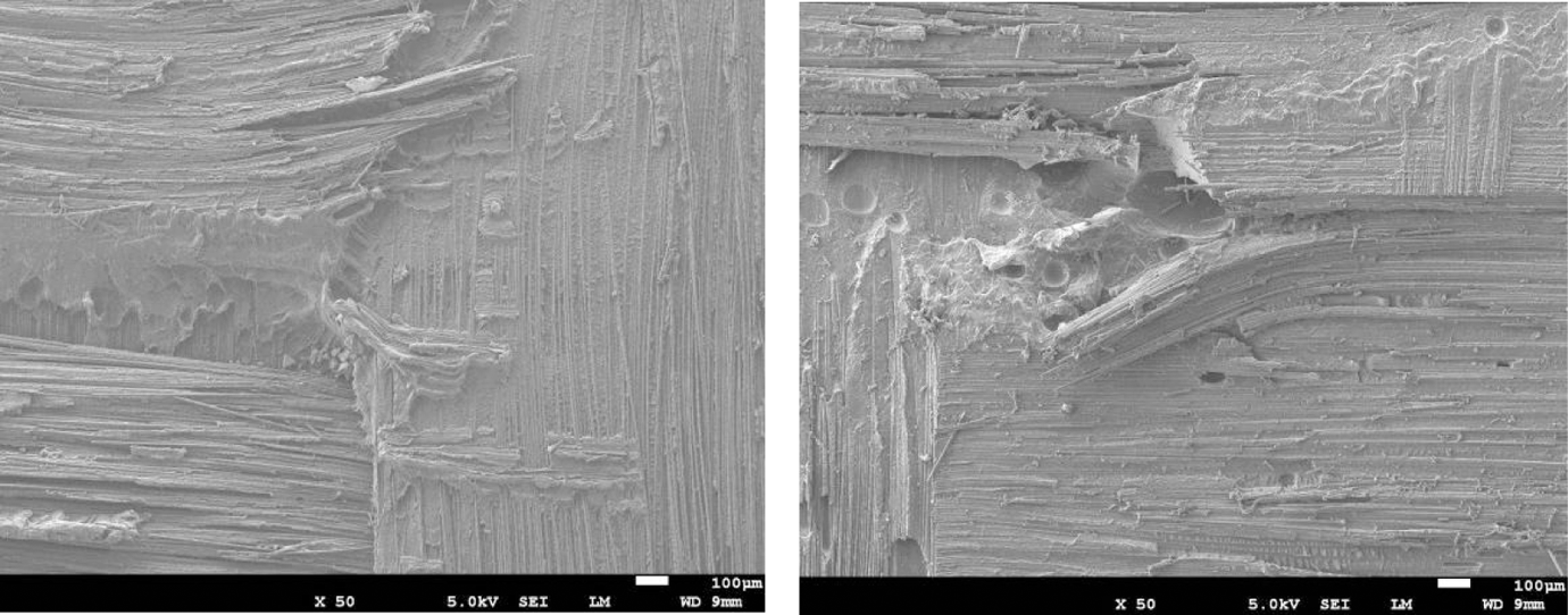
SEM micrographs of ultrasonic (left) and induction (right) fracture surfaces. SEM: scanning electron microscope.
From the analysis of the fracture surfaces of the three types of welds, it appears that the existence of poorly welded areas at the edges of the overlap is mostly responsible for the lower LSS value of the resistance welds. This can positively be improved by electrical insulation of the mesh heating element. 33 Similarly, practical absence of nonwelded areas and a similar failure mode results in comparable LSS values for induction and ultrasonic welds. It must be noted, however, that notable through-the-thickness porosity in the induction welded samples, which does not affect their LSS since most of the voids are out of the bondline, could compromise the durability of the material in the welded areas in, for instance, humid environments. It will also have an impact in quality (e.g. ultrasonic) inspection of the welds. Similarly, the low crystallinity level of the matrix resin at the ultrasonic-welded bondline locally reduces the chemical resistance of the composite.
Fatigue tests
The S-N curves (maximum stress relative to the static LSS) obtained from the single-lap fatigue tests for the three different types of welds are displayed in Figure 10. Despite the usual dispersion in this type of data, an overall similar behaviour can be observed for the three types of welds. However, the increase in number of cycles of failure with decreasing fatigue loads seems to be slightly less pronounced for ultrasonic welds, which might result in an inferior performance for very low fatigue loads. One of the possible causes might be a lower content of tough matrix resin at the interface as resulting from the welding parameters used in this study. Further research is necessary to assess such trend as well as to clarify its origin taking into account the complexity of the stresses developed in single-lap tests. Despite some slight trend divergences, the endurance limit occurred at around 40% of the static strength in the three cases. The samples that survived 10 6 fatigue cycles were statically tested and residual strength values between 85 and 100% of the static LSS were obtained, indicating the occurrence of little to no fatigue damage at that load level for all the three sorts of welds. The fracture surfaces of the fatigue samples showed similar general features to the ones described in the previous subsection for the static samples.
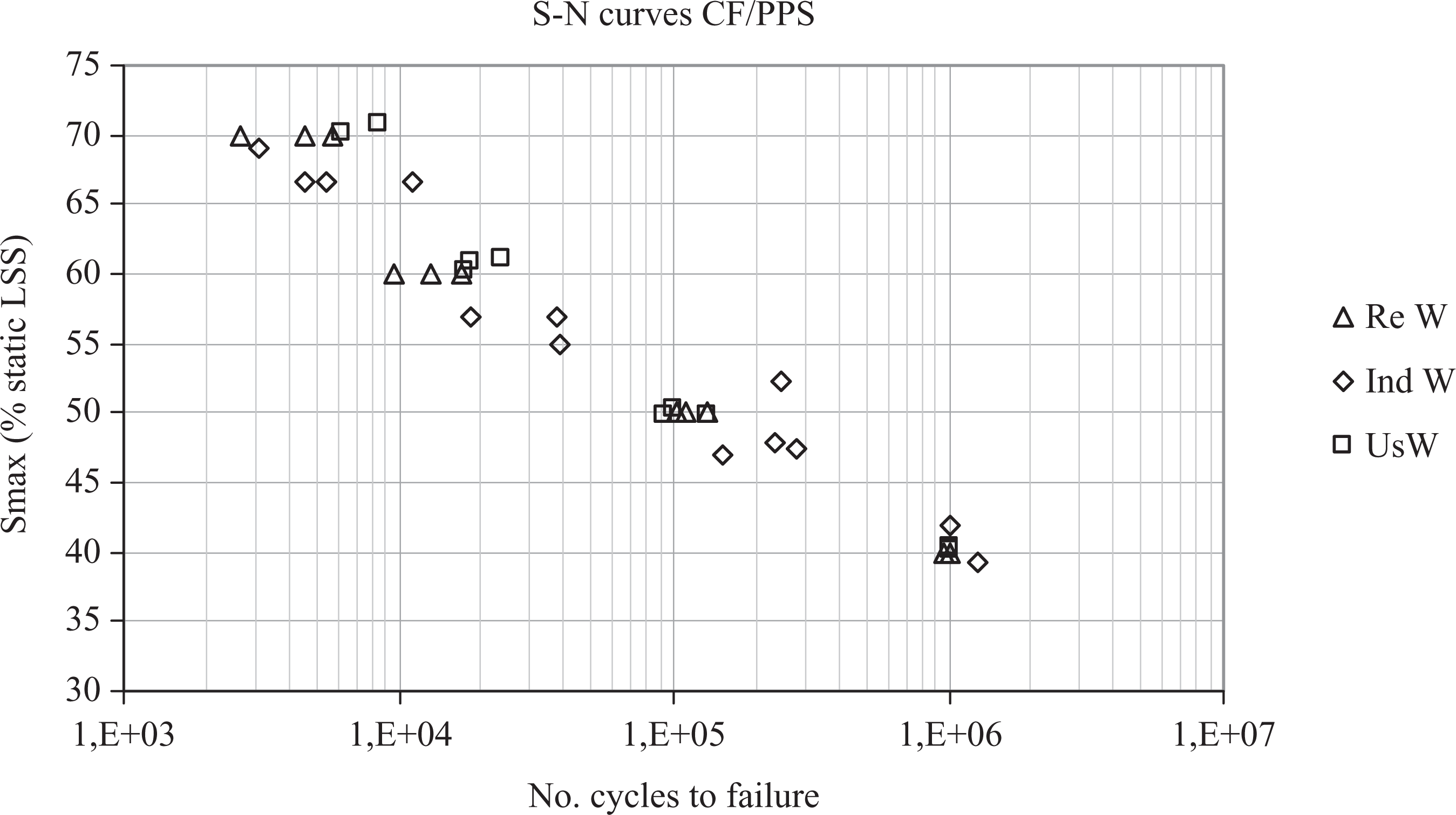
S-N fatigue data for resistance, induction and ultrasonically welded samples.
These results were comparable with previous research on the fatigue properties of different types of fusion bonds in thermoplastic composites 25,26 according to which no remarkable differences could be found in the relative S-N curves. As for the indefinite fatigue life threshold, in previous research single-lap resistance welded CF/PEEK samples were found to endure 1 million cycles at load levels between 35 and 40% of the static LSS, 23 similar to the results of the present article. However, there are differences with the fatigue results obtained for resistance-welded CF/PEKK and CF/PEI, 24,25 according to which indefinite fatigue life occurred at a lower load level (between 20 and 30%) and the residual static strengths were around 65%. These differences should be further investigated.
Welding variables
Table 2 summarizes the values of the main processing variables for resistance, ultrasonic and induction welding as performed in this research. It must be taken into account that most of these values are quite sensitive to the nature of the substrates (type of material, thickness and quality), particularly for those welding techniques such as ultrasonic and induction welding in which either the mechanical or electromagnetic waves travel through the substrates to reach the welding interface. Therefore, most of the conclusions obtained from these data cannot be easily generalized.
Main processing variables for three welding techniques.
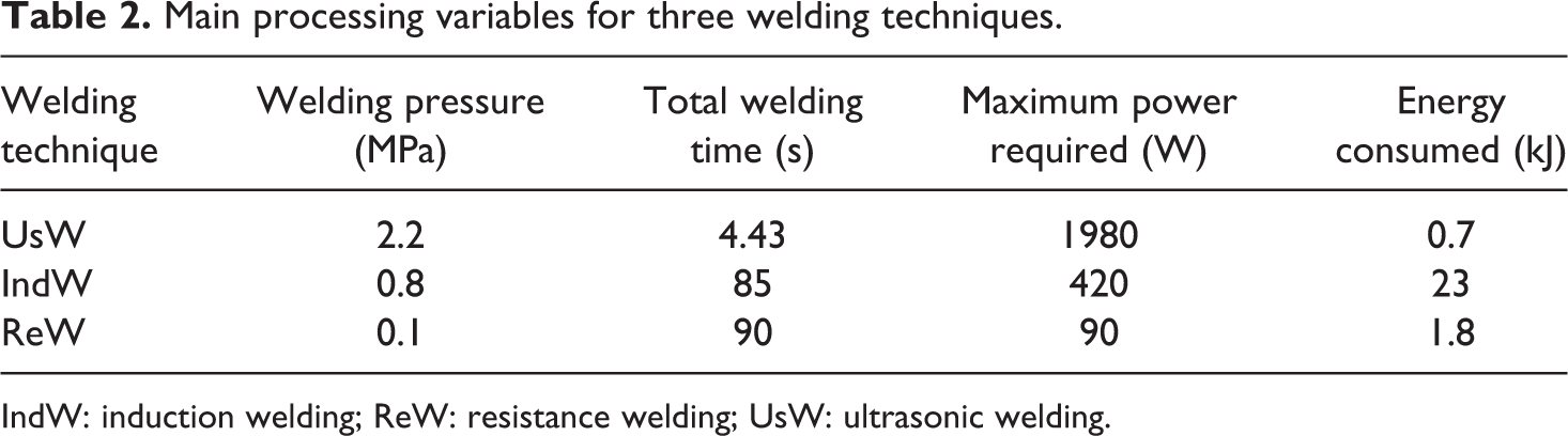
IndW: induction welding; ReW: resistance welding; UsW: ultrasonic welding.
As already expected, the heating time in ultrasonic welding is very short when compared with that of resistance and induction. The cooling or consolidation time is also very short but this is primarily influenced by the fact that during cooling the welding stack is in contact with a metal sonotrode and metal base towards which the heat generated by the welding process is rapidly transferred. Ultrasonic welding is therefore the fastest technique for spot welds. However, for medium-sized welds (up to around 1 m long with a 12.7-mm overlap, with the equipment used in this study), one-shot (or static) resistance welding is the most rapid process, since induction and ultrasonic welding must be carried out continuous or sequentially, and thus, the welding time is multiplied by the length of the weld. For welding areas beyond the maximum power that can be delivered by the resistance welding power unit, all the three processes must be applied in a continuous or sequential manner. At that level, the welding speed depends not only on the heating and consolidation rate but also on the way in which the process is implemented, so no general statements can be made about which process would be faster with the data obtained in this research.
Big differences in the power requirements were also found in this study among the three welding techniques. According to the data displayed in Table 2, the electrical power needed for resistance welding of individual samples is considerably lower. It must be noted that this value strongly depends on the nature and length of the heating element for one-shot resistance-welding processes. Induction welding has medium electrical power requirements, while ultrasonic welding has the highest. The combination of heating time and power results in relatively low energy consumption for ultrasonic and resistance welding whereas the energy consumed by the induction welding process is one order of magnitude higher.
Also noticeable is the relatively high pressure used for the ultrasonic welding process. In the induction and resistance welding process, pressure is applied to prevent delamination of the heat affected areas of the laminate and to achieve consolidation of the weld. On the contrary, the welding pressure is directly involved in the ultrasonic heating mechanisms. 4 Empirical experience shows that high pressures are needed in order to concentrate heat generation at the welding interface and to limit the depth of the heat affected area.
Conclusions
An experimental evaluation of ultrasonic, induction and resistance welding of CF/PPS composites was presented in this article. Induction welding was based on the ability of the CF fabric reinforcement to create closed loop electrical paths and hence no foreign susceptor was used at the welding interface. A fine stainless-steel mesh supplemented with some extra PPS resin was used in the resistance welding process as heating element. Loose PPS strips with moulded triangular shapes were utilized to direct the vibration energy to the welding interface in the ultrasonic welding process. Individual single-lap specimens were welded using these three techniques and their static and dynamic properties were evaluated. Cross-sections and fracture surfaces were analysed in order to get more complete insight into the welding processes and the quality of the welds. Other features of the welding processes such as processing time or energy consumed were also examined.
Both ultrasonic and induction welding led to 100% welded areas with mostly interlaminar failure and similar static LSS values. Resistance welding resulted in a good quality bond in around 85% of the overlap area and nonwelded edges. These originated in the too short welding times required to avoid current leakage and led to a 15% drop in the LSS values when compared with ultrasonic and induction welding. The use of proper insulation for the metal mesh heating element is yet expected to easily overcome these issues. The tension–tension fatigue performance was similar for all the three types of welds with indefinite fatigue limits around 40% of the corresponding static LSS. Little to no damage was found in the samples that survived 1 million cycles. However, some process-related features of the welds indicated the following potential concerns. Through-the-thickness porosity caused by bulk heating in induction welding could result in durability issues. Similarly, the effect of the embedded mesh in the durability of resistance welds is yet to be assessed. Moreover, very fast cooling rates in ultrasonic welding might lead to reduced chemical resistance of the welded part. The thermal deformation undergone by one of the substrates during induction welding should also be taken into account for aerodynamic surfaces or when aesthetics of the final parts is of importance.
Regarding the welding processes themselves, ultrasonic welding showed by far the shortest welding time for welding of small areas. Nevertheless, one-shot resistance welding is the fastest assembly technique for medium-sized welds. The results obtained in this study do not allow drawing any conclusions about the process speeds for very long welds, since they are influenced by the way in which the continuous or sequential welding processes are set up. The highest power requirements, very closely related with the size of the welds, were for ultrasonic welding and the lowest were for resistance welding. As a result of the remarkably shorter heating times, ultrasonic welding yielded the lowest energy consumption despite the high power required. Finally, due to its involvement in the heating process, the welding pressure for ultrasonic welding is remarkably higher than the usual pressure levels for induction or resistance welding.
Footnotes
Acknowledgements
The authors would like to thank the German Academic Exchange Service (DAAD) for financially supporting Lars Moser. They would also like to acknowledge the work of Fred Bosch, Jose L Mechato, FX Trudeau and E Robert on the ultrasonic welding process as well as on the fatigue tests.
Funding
This research received no specific grant from any funding agency in the public, commercial, or not-for-profit sectors.