
Abstract
The effects of the top ply orientation and the addition of a resin-rich laminate surface layer on the quasi-static and fatigue strength of overmoulded composite joints were investigated experimentally. Therefore, rib coupons with varied laminate configurations were manufactured in a dual-step overmoulding process. The coupons, made from short carbon fibre-filled PEEK and unidirectional continuous carbon fibre-reinforced LMPAEK, were subjected to a rib-pull-off test. The additional resin-rich surface layer on the laminate significantly increased the pull-off strength and equalised the effect of the top ply orientation. Without the resin-rich interlayer, a significant effect of the top ply orientation was observed. With the top ply being oriented perpendicular to the rib, failure occurred mostly in the interface, while higher pull-off strength was associated with the fibres running parallel to the rib. This was attributed to a predominant laminate failure mode. A new interfacial void pattern was observed to a larger extent in specimens with the resin-rich interlayer and a hypothesis for its genesis is presented. Compared to monotonic, quasi-static loading, the cyclic fatigue loading up to 106 cycles resulted in a typical overall reduction of the ultimate pull-off strength. However, the strengthening effect of the resin-rich layer and the effect of the top ply orientation persisted also under cyclic fatigue loading.
Keywords
Introduction
Composites overmoulding is a highly potential technology for possible future aircraft structural applications. This can be concluded from the successful adoption of composites overmoulding in the automotive industry and some demonstrator components from the aerospace sector.1–4 It allows combining short fibre-reinforced injection mouldings with high-performance continuous fibre-reinforced laminated composites into hybrid parts. The interface is often deemed as a potential weak spot of such structures. 5 Strength predictions of such hybrid parts are still an issue to be solved. 6 These require a better understanding of the behaviour of the joint. As being typical for composites and other materials, the manufacturing process strongly affects the final properties. Early studies on the processing effects on the joint strength were conducted for engineering polymers.7–9 Nowadays, such materials are commonly used for large series production in the automotive industry.10–12 Overmoulding with high-performance thermoplastics, such as poly (p-phenylene sulfide) (PPS) and the family of polyaryletherketones (PAEK), including polyetheretherketone (PEEK) and polyetherketoneketone (PEKK), has gained interest in the aircraft industry in the recent years.13,14 Strict safety requirements create the need for deeper understanding of material behaviour, quality and processing effects. Some studies investigated PPS and PEEK-based material systems.6,15–17 However, quantifying fracture properties of the overmoulding interface remains a challenging task. Tri-Mack 14 experimented with a block shear test and claimed to reach 85% of the strength of the laminate material. Hartley et al. 5 presented an approach to determine the fracture energy release rate of the interface of glass fibre-reinforced polycarbonate using an adapted double cantilever beam test. They reported a strong effect of the orientation of the woven fabric laminate on the fracture energy release rate. Donderwinkel et al. 18 reported a dedicated coupon design and results on the flow path length effect on short beam shear strength for a PEEK-PAEK material combination. Joppich et al. 19 proposed a rib coupon for shear, pull-off and peel testing. Their concept is advantageous because different properties could be characterised from only one kind of coupon without mixing potential effects of different moulds, geometries and actual processing conditions.
The overmoulding technology is sometimes also termed as composites overmoulding, injection overmoulding, hybrid moulding or assembly injection moulding. A detailed overview of special process variants of injection moulding can also be found elsewhere. 20 However, the different terms commonly describe processes where a multi-material component is created in an injection moulding step. In our case the overmoulded component consist of a continuous fibre reinforced laminate with a thermoplastic matrix polymer, which is why we term the process as composites overmoulding or just overmoulding.
Two process variants can be distinguished: the single-step and the dual-step variants.
6
Both are schematically shown in Figure 1. The main difference lies in forming and consolidation of the laminate. Schematic of the single-step and dual-step variants of the composites overmoulding process.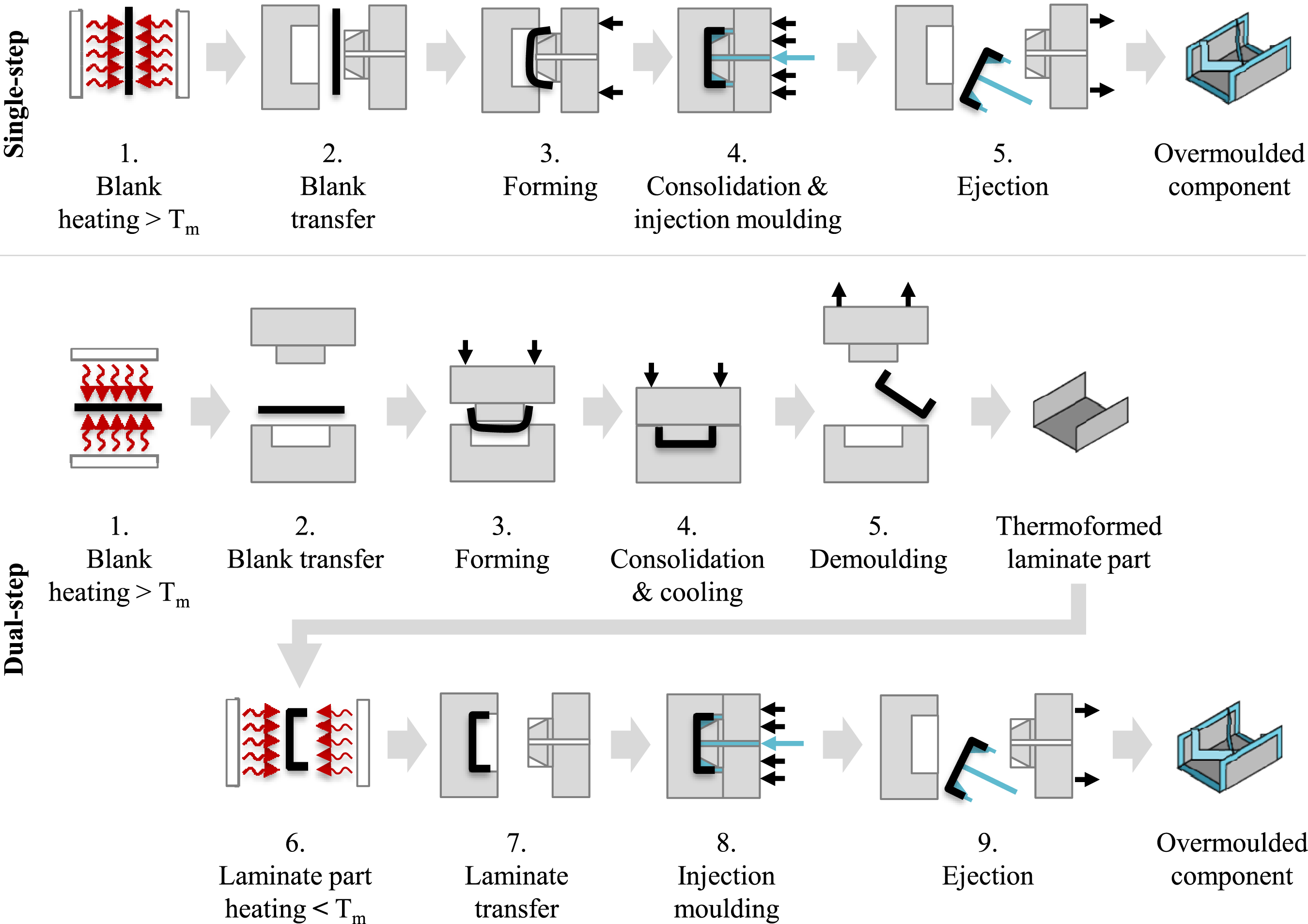
In the dual-step process, the laminate is formed and consolidated in a separate step prior to the injection moulding step. This may be done by generating the composite layup using automated tape laying (ATL) or automated fibre placement (AFP) and subsequent hot press consolidation (HPC). Another route is thermoforming of flat, preconsolidated laminates into the final shape. The latter is shown in Figure 1. There, the laminate or so-called blank is being preheated far above its melting temperature, usually in an infrared oven, and then transferred onto a hydraulic press with a dedicated thermoforming mould. As the mould is kept isothermal at a temperature in the region of the crystallisation temperature, the molten blank cools rapidly while sufficiently high pressure is applied. After demoulding, the contour of the laminate part is usually machined. In the second step, the well consolidated and readily shaped laminate part is preheated somewhat below its melting temperature but high enough to melt at the interface when making contact with the much hotter injected moulding compound. Like in conventional injection moulding, the filling phase usually lasts for less than two seconds and is followed by the packing phase taking usually several tens of seconds. There, a certain injection pressure profile is maintained in order to let additional melt enter the mould to compensate for the progressively cooling and shrinking material. The subsequent cooling phase begins when no more mass can be packed into the mould because the part or the runner are already frozen. It ends when the part is cooled enough to completely solidify and crystallise. This takes several tens of seconds to a minute or two, depending on the part. Finally, the overmoulded component is ejected and cools to ambient temperature outside the injection mould.
In the single-step process both steps are combined and only the injection mould is required. The preconsolidated thermoplastic laminate is heated well above its melting temperature, transferred into the open injection mould and formed by the closing motion. So, the subsequent injection moulding and the thermoforming steps are done in parallel. Like in thermoforming processes, short transfer times are essential for the laminate not to freeze before being formed and experiencing sufficient consolidation pressure.
Both process variants have their advantages and disadvantages. On the one hand, the single-step process is more economical because it omits the separate thermoforming step and eventual contour trimming operations. On the other hand, combining heating, thermoforming and injection moulding increases the complexity. Also, the laminate’s contour and the fibre orientation are less precise and the laminate may undergo significant deformation, making the topology of the interface less predictable. In experiments by Valverde et al. 16 broken continuous fibres were seen for higher laminate preheating temperatures, i.e. the single-step process. In comparison, the dual-step process rather conserves the laminate part quality with only limited deformation. Quality of laminate and injection moulded parts can be adjusted separately without direct interactions. Furthermore, sink marks at the back of the overmoulded laminate are also reduced. Downsides of the dual-step process are the obviously higher costs and increased risk of weak bond and initial cracks. 6
So, for applications with very large part numbers per year, such as millions for instance in the automotive industry, lead times and cost are dominant criteria. Only the single-step process is applied there. In the aircraft industry however, low structural weight and performance are stronger drivers along with strict quality requirements while part counts are much lower. Reproducibly low porosity, fibre angle deviation and waviness are required. Therefore, the dual-step process could be favourable.
Consequently, this study is focused on dual-step overmoulding. It aims at investigating effects of flow path length, laminate orientation with respect to the rib and a resin-rich layer at the laminate surface on the strength of the overmoulded joint. The chosen material system consists of a lower-melting PAEK-based laminate material which is being overmoulded with a higher-melting PEEK-based moulding compound. This material choice is made because it is assumed to enlarge the processing window so that the dual-step overmoulding process can be applied with reduced risk of an insufficiently healed interface.
This paper is structured as follows: At first, the materials and experimental methods for coupon manufacture and testing as well as the test plans for two series of experiments are described. The first one is a preliminary trial exploring the effects of processing parameters on qualitative aspects such as laminate deformation, voids and initial cracks. The second one is the main experiment, where quasi-static and cyclic rib pull-off tests were conducted with overmoulded specimens with varied laminate configurations. Subsequently, the results are discussed and conclusions are drawn.
Experimental
Materials
The injection moulded sections of the test coupons consist of VICTREX™ PEEK 90HMF40. 21 This injection moulding compound contains 40 wt % of short carbon fibres in a PEEK matrix. Supplier is Victrex plc., UK. This material was selected because it is qualified for structural components in the aircraft industry, 22 has relatively high Youngs’s modulus compared to other short fibre-filled injection moulding compounds and low shrinkage. The latter property is crucial to minimise residual stresses when used in hybrid structures where the laminate material also has a low coefficient of thermal expansion.
The continuous fibre-reinforced laminate material is VICTREX™ AE™250 UDT,
23
a unidirectional (UD) composite prepreg tape comprising a high performance semi-crystalline thermoplastic matrix and carbon fibres. The matrix polymer is VICTREX™ AE™ 250, also known as low-melt-PAEK or just LMPAEK, a PEEK-compatible PAEK. It features a similar glass transition onset (
Some laminates are consolidated with an additional layer of LMPAEK polymer at the outer plies. Therefore, a 60 µm thick LMPAEK film is used (APTIV AE 250 LMPAEK™ FILM 060), supplied also by Victrex plc., UK.
Test Coupon Design
Figure 2 depicts the overmoulding test coupon consisting of a flat laminate with quasi-isotropic layup and an injection moulded rib. The dedicated injection mould is shown in Figure 4. It features two rib cavities, one for a 3.5 mm thick rib and another for a 4.5 mm thick rib. However, in this study the thinner ribs are used. The cold runner system has switchable elements allowing to choose between filling the rib either from one end or from both ends. Only the single-gate configuration is used here. Overmoulding test coupon with dimensions and laminate configurations.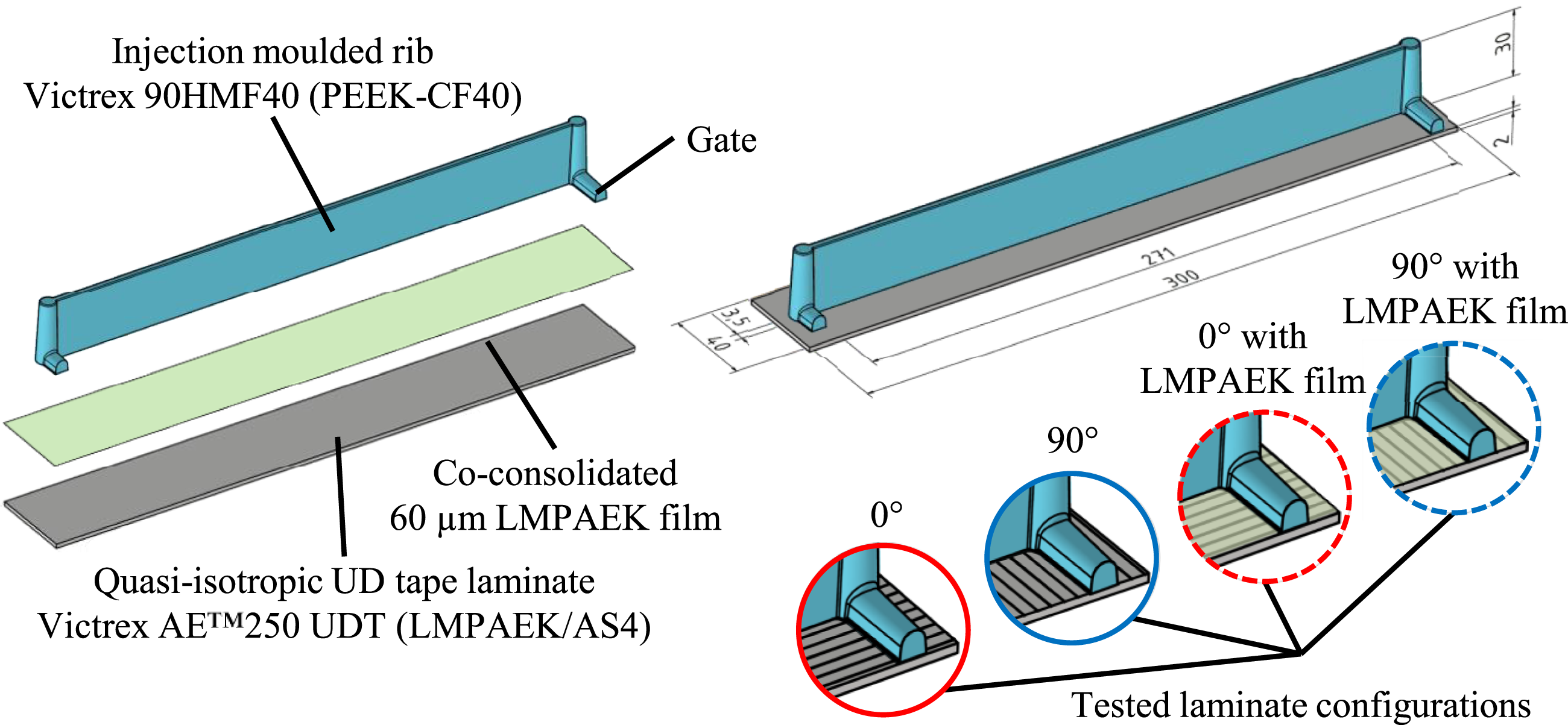
Typically, for processing of PEEK materials the mould should be at temperatures above 200°C. 21 This usually requires water or oil tempering. It would be desirable to eliminate the need for such equipment. Hence the thermal mould concept is based on electric heating only. Heating cartridges are distributed over the mould and can be set individually. Passive cooling happens by convective and radiative heat transfer at the outer mould surfaces and at the parting plane during opening times.
The laminate fits into a recess in the fixed mould half. It is held in place by a spring plunger. At room temperature, the recess is 2 mm deep and the laminate is also 2 mm thick. When both mould and laminate are heated up, the laminate is a bit thicker than the recess due to larger transverse thermal expansion of the laminate compared to the steel. Consequently, the mould halves first make contact at the laminate. The clamping force exerted by the injection moulding machine is enough to compress the laminate so that the mould halves also make contact in the whole parting plane.
Preparation of Laminates
Due to the given thickness requirement of 2 mm and the consolidated ply thickness of the material, the layup has to comprise 15 plies to fit into the mould. Due to the odd number of 15 plies, the quasi-isotropic layup is symmetric, but not perfectly balanced. The layup is fabricated by cutting patches from the 150 mm wide raw material, positioning the patches side-by-side without gaps or overlaps and spot-welding them together using a soldering iron. According to the experimental plan described below, two of the four layups are produced with an additional layer of LMPAEK film on top of the outer plies. Also, the layup is rotated by 90° in two cases. The completed stacking is 432 mm long and 312 mm wide.
Each stacking is consolidated in a hot press. The consolidation setup is shown in Figure 3. It comprises a 900 kN hydraulic hot press (RUCKS KV 228.00 from RUCKS Maschinenbau GmbH, Glauchau, Germany) with an upper and a lower press plate with electric heating cartridges and cooling channels for air or water cooling. The press consolidation setup between the press plates consists of a compliant layer of glass fabric with 390 g/m2, 4 mm thick stain-less steel caul sheets, 25 µm thick polyimide (PI) release film (UPILEX 25S from UBE Europe GmbH) as well as the UD tape stacking being placed inside an 8 mm thick steel frame to prevent excessive squeeze flow. A NiCr-NiAl (Type K) thermocouple is placed within the tape stacking to monitor the actual laminate temperature. Schematic of the hot press consolidation setup.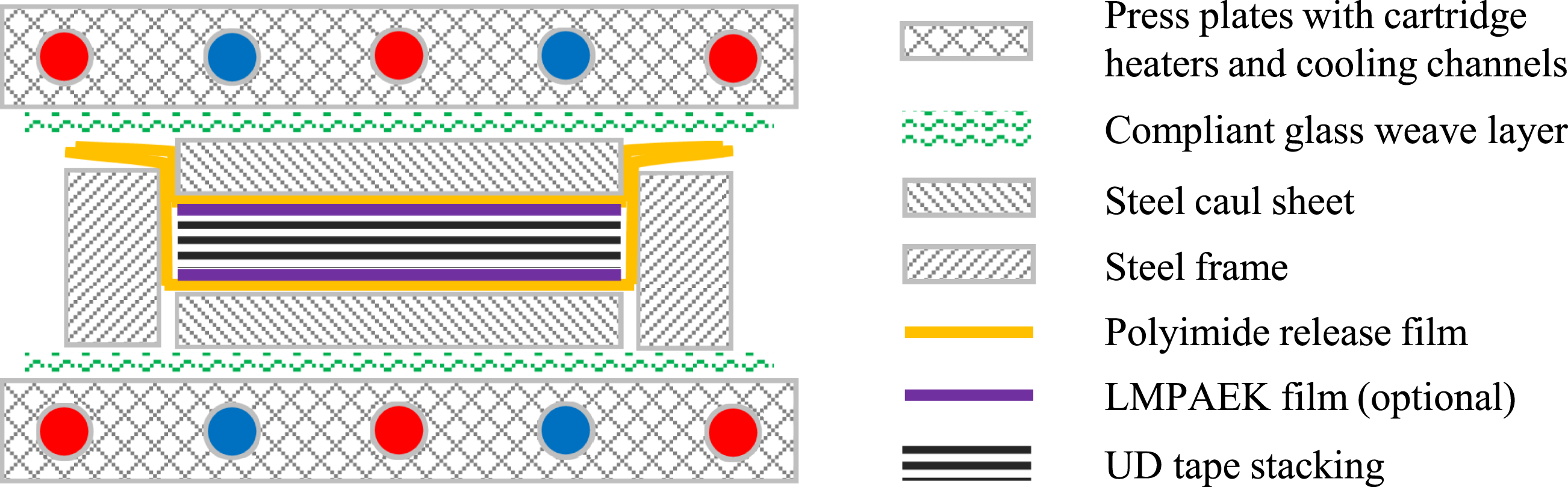
A specific pressure of 0.2 MPa is maintained during heating, dwell and cooling phases until the laminate temperature falls below 315°C. Then, the pressure is increased to 1 MPa for further cooling. Above 180°C, the press is cooled with air resulting in an average cooling rate of −1.5 K/min. Below 180°C, water cooling is activated resulting in a cooling rate of −10 K/min.
The consolidated laminates measure 435 × 315 × 2 mm. From each laminate, 10 strips with 300 × 40 × 2 mm are prepared using a circular saw. Prior to further processing in the overmoulding process, the laminates are cleaned with acetone and dried at 130°C for 5 h in a convection oven.
Overmoulding
Overmoulding is performed with an injection moulding machine ENGEL victory 860/260 tech with a 45 mm diameter screw and a shut-off nozzle. A convection oven for insert preheating is positioned besides the machine and set to 250°C. Each laminate stays in the oven for 15 min. The injection moulding machine is equipped with a movable infrared (IR) radiator device which can be lowered into the opened mould, see Figure 4. The IR radiator is directed towards the surface of the laminate insert. In this way the insert surface temperature could be raised higher than the oven temperature in order to also test the transition towards the single-step process variant, where the whole laminate would be heated above its melting point. The mould temperature is set so that the parting plane close to the cavity reaches 230°C and the melt temperature should have been as hot as the screw cylinder heating which is set to 420°C. Injection mould with movable IR-heater.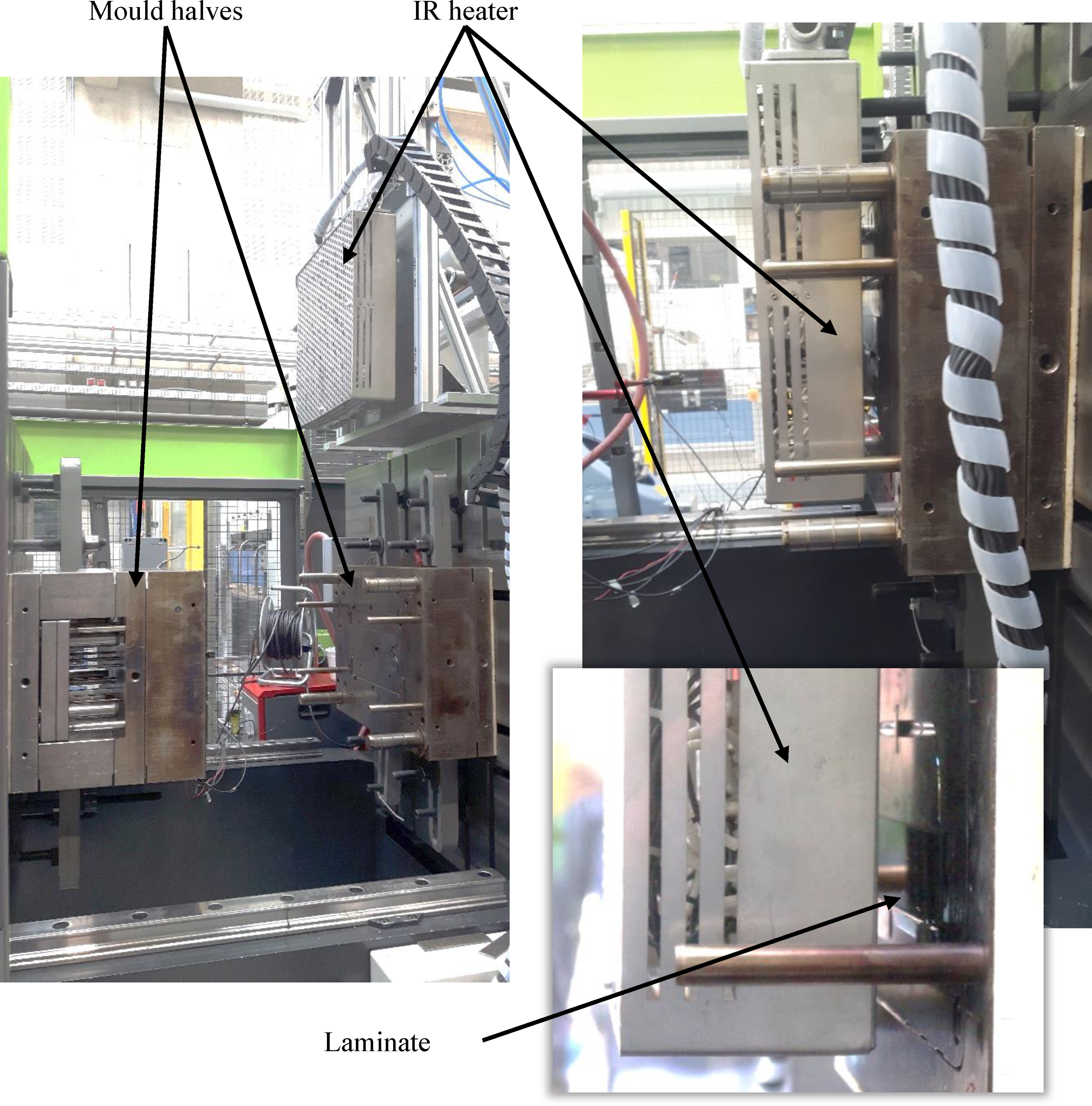
The overmoulding cycle begins with the mould being opened. The preheated laminate is taken out from the convection oven and placed manually into a dedicated recess of the fixed mould half. This step takes about 10 s. The IR heater, set to 500°C in a distance of 30 mm to the laminate insert, is then moved down into the mould and held there for 30 s. From preliminary trials, 30 s were identified to be sufficient so that the insert surface reaches 300°C, but did not deconsolidate. After moving the IR heater back up, the mould closes and the filling phase begins. Filling takes 1.2 s with a maximum specific injection pressure of 200 MPa at 112 cm³/s. Subsequently, a packing pressure of 80 MPa is applied for 6 s. Then the cooling phase follows, lasting for 80 s until mould opening and ejection of the coupon. Finally, the coupon cools down to ambient temperature. Figure 5 visualises this sequence of process steps. Overview of the overmoulding process steps.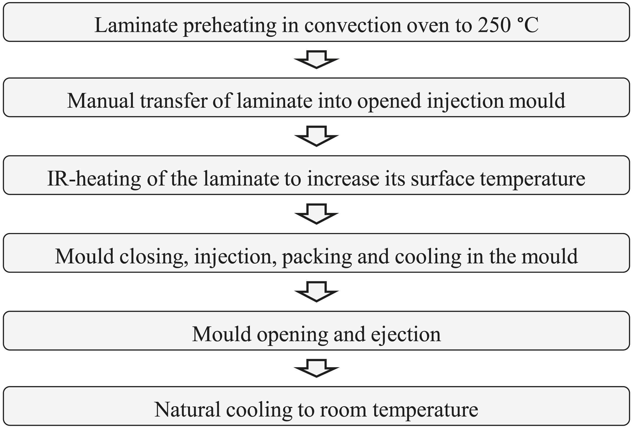
Injection moulding processes typically require several shots to establish a thermal balance within both mould and machine. Consequently, after setting up the process, a total of 15 specimens are overmoulded with the final processing parameters and discarded. As seen from preliminary trials, the mould can further accumulate heat even after several hours of preheating. This results in slightly different thermal conditions for the first and last shot. In order to randomize potential effects, the four different kinds of laminates are processed in an alternating order.
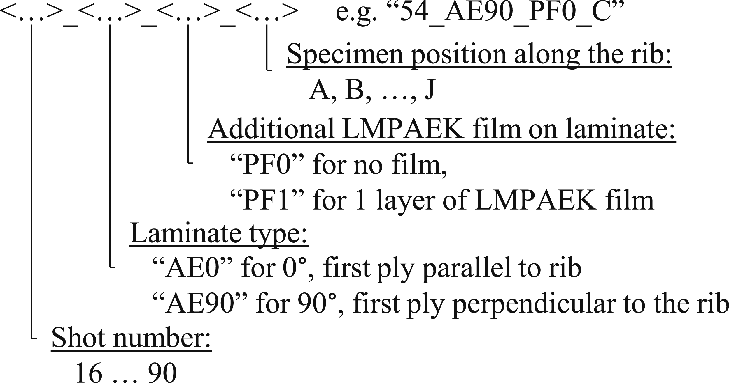
The shot number and laminate configuration are written to each coupon right after ejection. In order to prevent confusion of the test specimens, coloured adhesive labels are attached to each rib as shown in Figure 6. The labels carry unique designations for each of the 25 mm long sections according to the scheme shown in Figure 7. Overmoulding rib coupon with colour-labelled specimen sections. Specimen designation scheme.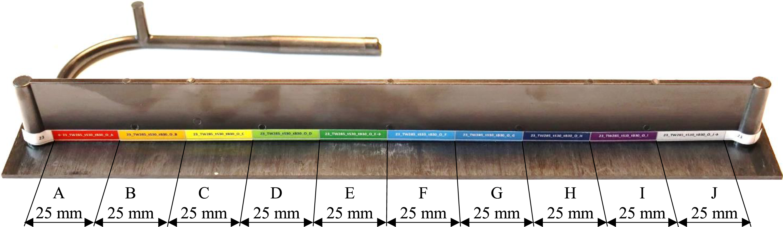
Preparation of Test Specimens from Coupons
For the rib pull-off experiments, 25 mm long sections are prepared from the coupon using a band saw for cutting, where the coupon rests on the laminate and the blade is running through it from above. In this way, the cutting forces are acting almost perpendicular to the interface and damage to the interface should be avoided as much as possible. The specimens are numbered alphabetically from A to J along the flow direction. The end face of every specimen is ground to remove potential initial cracks originating from the band saw. From a preliminary experiment it is concluded that the band saw cutting may induce small delamination reaching not deeper than 0.25 mm into the specimen. Consequently, at least 0.3 mm are ground from the end faces.
Quasi-Static Pull-Off Test
A dedicated fixture is designed for the rib pull-off test as shown in Figure 8. Its purpose is to use it in different testing machines with different grips but to have the same boundary conditions at the laminate i.e., the distance of the laminate fixture from the rib and the compliance of the laminate fixture. The fixture consists of bolted upper and lower steel frames. In between the frames there is a slot in which the specimen and a wedge can be inserted. The wedge is driven by a screw and pushes the specimen against the lower frame to clamp it in the fixture. The lower frame has a 6 mm wide slot through which the rib protrudes towards the lower vice grip that is clamping the rib. The upper frame features a steel rib which is clamped by the opposite vice grip. The vice grips are part of a jig that is designed to tilt the vice grips around a horizontal axis running through the overmoulded interface, allowing to adjust the loading direction. With this, also mixed modes of shear and tension or just shearing could be applied to the overmoulded specimen. However, for this study only the tensile loading configuration is used. Test setup for quasi-static rib pull-off test: Jig with vice grips mounted to the testing machine (left) and specimen fixture (right).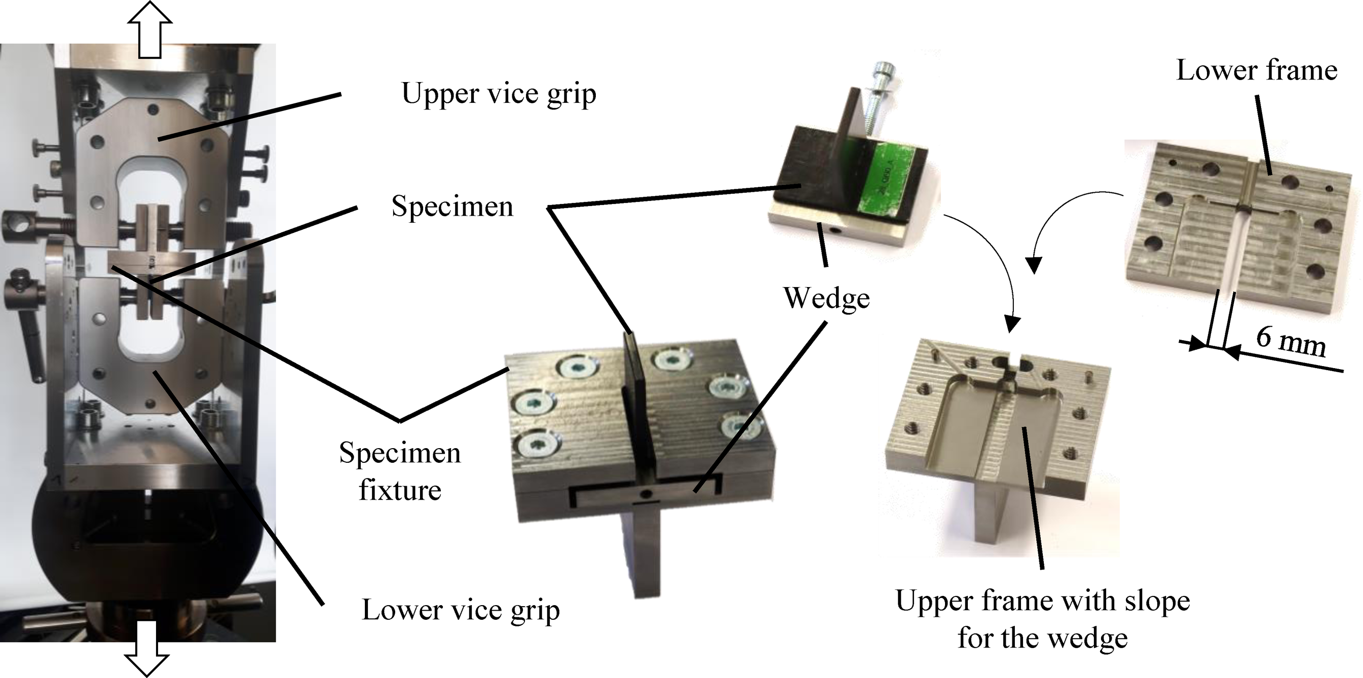
For the monotonic, quasi-static test in standard atmosphere according to,
25
a universal testing machine Zwick Z250 is used with a 10 kN load cell. For mounting the specimen, the wedge of the fixture is loosened so that the specimen can be pushed against an end stop within the fixture. As gravity ensures contact between the laminate and the lower fixture frame, the lower vice grip is closed. Now the specimen is centred with respect to the machine axis. Then the screw of the wedge is tightened, locking the laminate from above. During grip tightening, the machine automatically compensates the crosshead displacement to maintain 0 N of pull-off force. During the test the cross-head speed is 1 mm/min. Force and displacement are recorded by the machine software until the specimen separated completely. For each specimen the pull-off strength
Fatigue Test
Fatigue tests are conducted in standard atmosphere according to25 with a dynamic testing machine Instron ElectroPuls E10000 with a 10 kN load cell. The same specimen fixture is used and clamped by the machines pneumatic wedge grippers. A sinusoidal pulsating tensile load with frequency
Optical Microscopy
For visual inspection of the fracture surfaces a macroscope WILD M420 with 6.3 to 32-fold magnification is used. Digital images are taken using an attached Olympus DP26 camera. Micrographs of the overmoulded joint are obtained using an optical microscope ZEISS Axioplan. The micrographs look at the cross section between adjacent specimen positions along the rib coupon. Extra care is taken during preparation in order not to damage the interface.
Micro-computed Tomography
Non-destructive testing is performed by means of micro-computed tomography (µCT) in order to assess whether there are voids in the joint, especially at the interface, and to check if interface cracks observed in micrographs are present only at the polished cross sections or along the whole specimen. Therefore, a GE Phoenix v|tome|x m research edition from General Electric Company is used. In order to increase the scan resolution at the interface, the laminate and rib are trimmed using a manual hack saw prior to the measurement. The obtained spatial resolution of the tomography scans is 4.25 µm. Post-processing of the scan data is performed with VGSTUDIO MAX from Volume Graphics GmbH.
Preliminary Manufacturing Trial
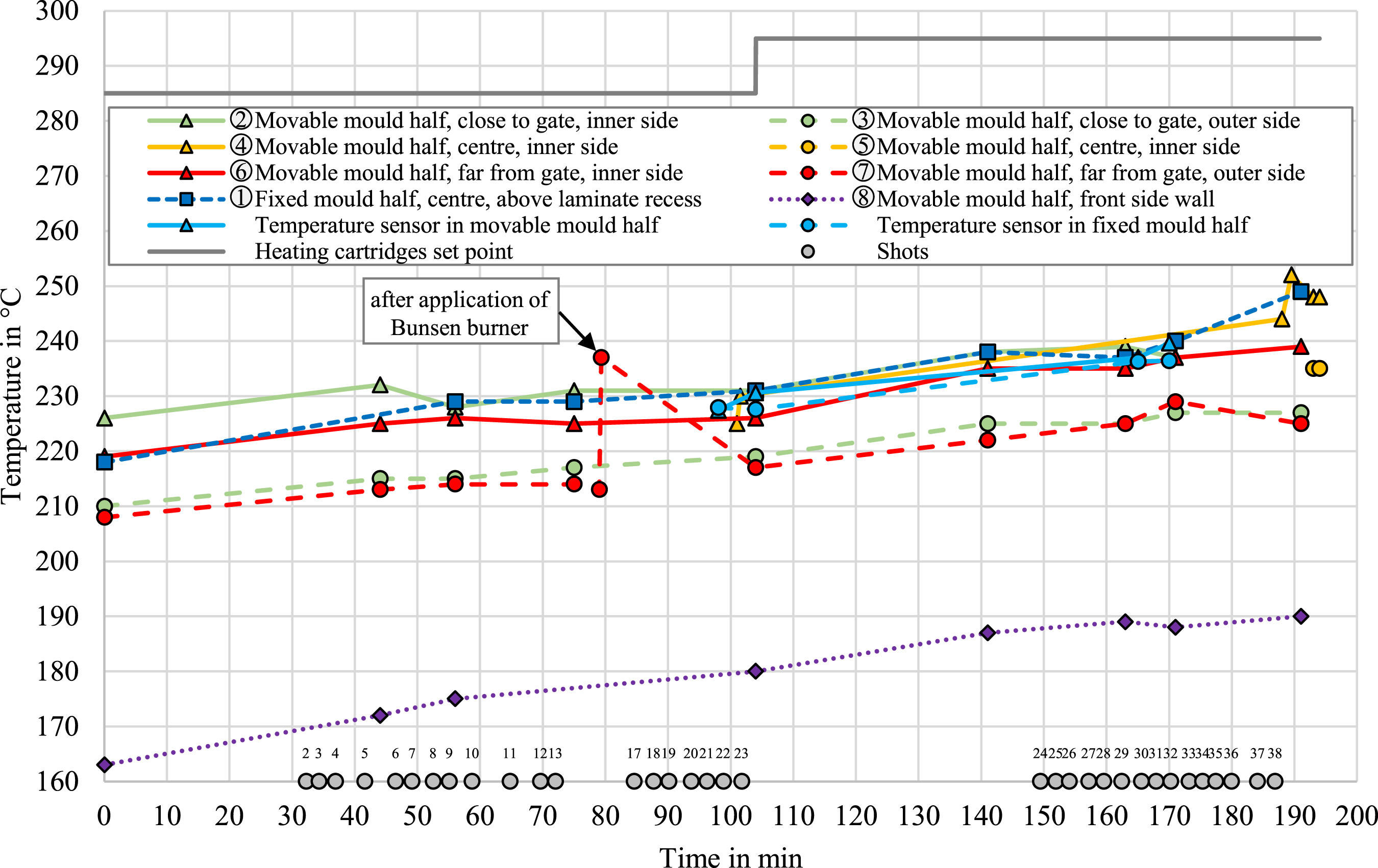
In order to identify the set of process parameters for the main experiment, a preliminary manufacturing trial is conducted. The electrical heating cartridges of the injection mould are initially set to Locations for the temperature measurements plotted in Figure 10. Temperature recordings from the preliminary trial along with the shot times and numbers.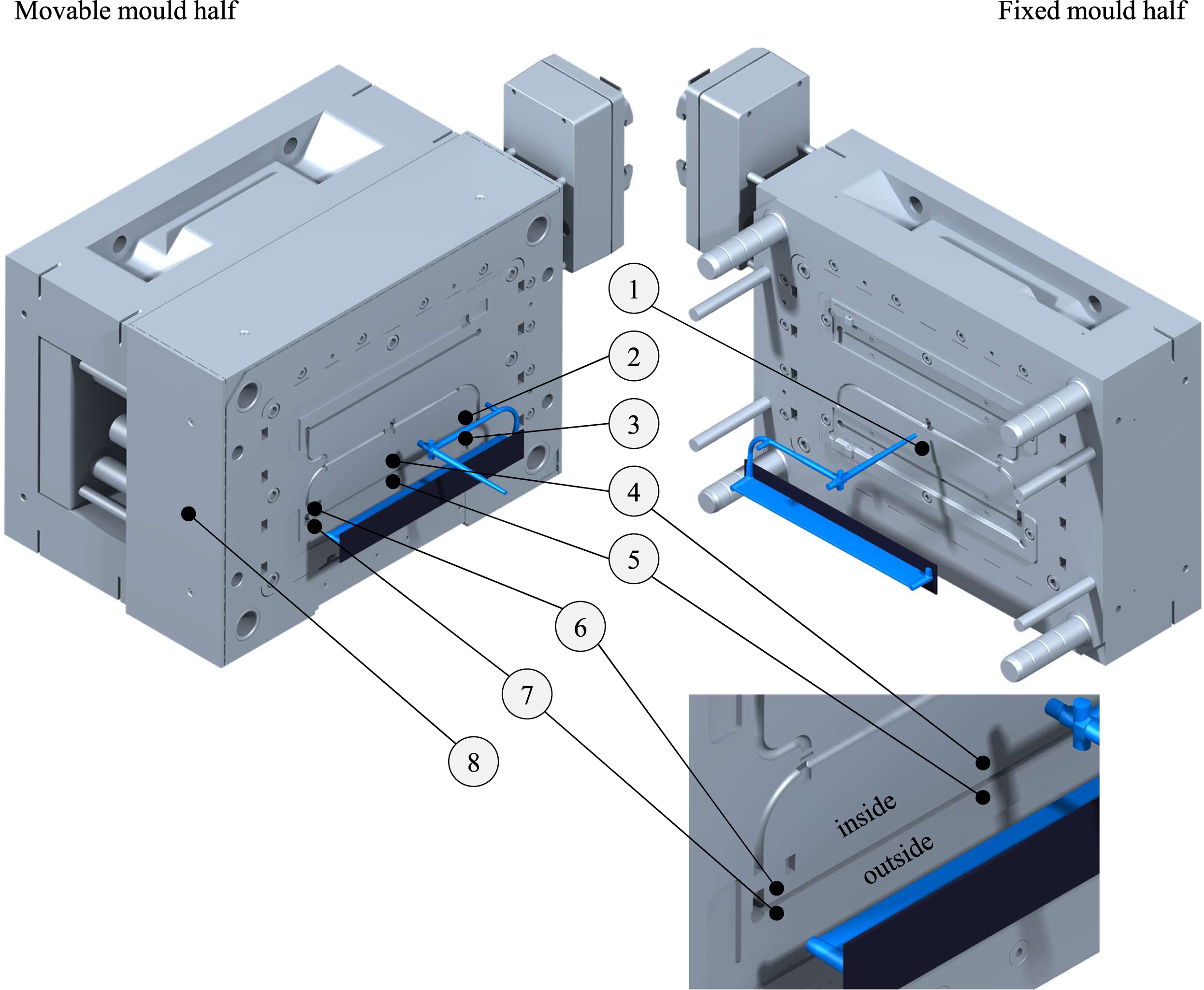
Each coupon is cut in 25 mm long sections. Micrographs are prepared at selected cross sections as follows with the respective designations: at beginning of section A (“|A”), between sections C and D (“C|D”), between sections E and F (“E|F”), between sections G and H (“G|H”) and at the end of section J (“J|”). From each micrograph, the following is evaluated: • Are there initial cracks at the inside and outside interface corners and if yes, how long are these? • Are there voids at the interface? • Is the interface flat or did laminate material migrate into the rib?
Additionally, sections B, C, F, G and I are subjected to the quasi-static pull-off test. However, not every specimen is tested for this quick screening.
Test Plan for the Main Experiment
The manufacturing parameters of the overmoulding process are kept constant for all coupons as described above. These are chosen based on the preliminary experiments described above. Prior to the test coupons, at least 20 shots are made and discarded to achieve a thermally stable process state. The cavity surface temperature is logged before every shot. In order to prevent a systematic error associated with the shot sequence, at least three specimens with identical configuration are selected for every test having a low, medium and high shot number.
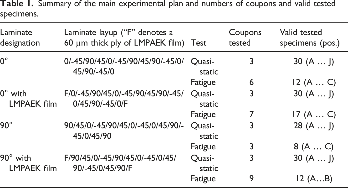
Summary of the main experimental plan and numbers of coupons and valid tested specimens.
Results of Preliminary Trial
Mould Temperature
The recorded temperatures from the preliminary trial are shown in Figure 10. The numbers for several locations refer to Figure 9. Obviously, even after at least 4 h of preheating, the temperature within and at the outside of the mould still kept rising. However, the rate decayed towards a thermal balance between the supplied and dissipated heat. It should be noted that the mould was not equipped with thermal insulation in the first place. After about 10 shots were made, the temperature measured near the cavity in the parting plane quickly reached a steady state. Nevertheless, a difference of up to 18 K remained with the largest differences between the inside and outside positions at similar flow path lengths. Elevating the set point for the heating cartridges resulted in a noticeable increase of the recorded temperatures. However, the parting plane temperature remained about 60 K below the set point. This means a large gradient being within the mould. Applying the Bunsen burner at positions 4 and 5 increased the surface temperature by around 25 K.
Initial Cracks
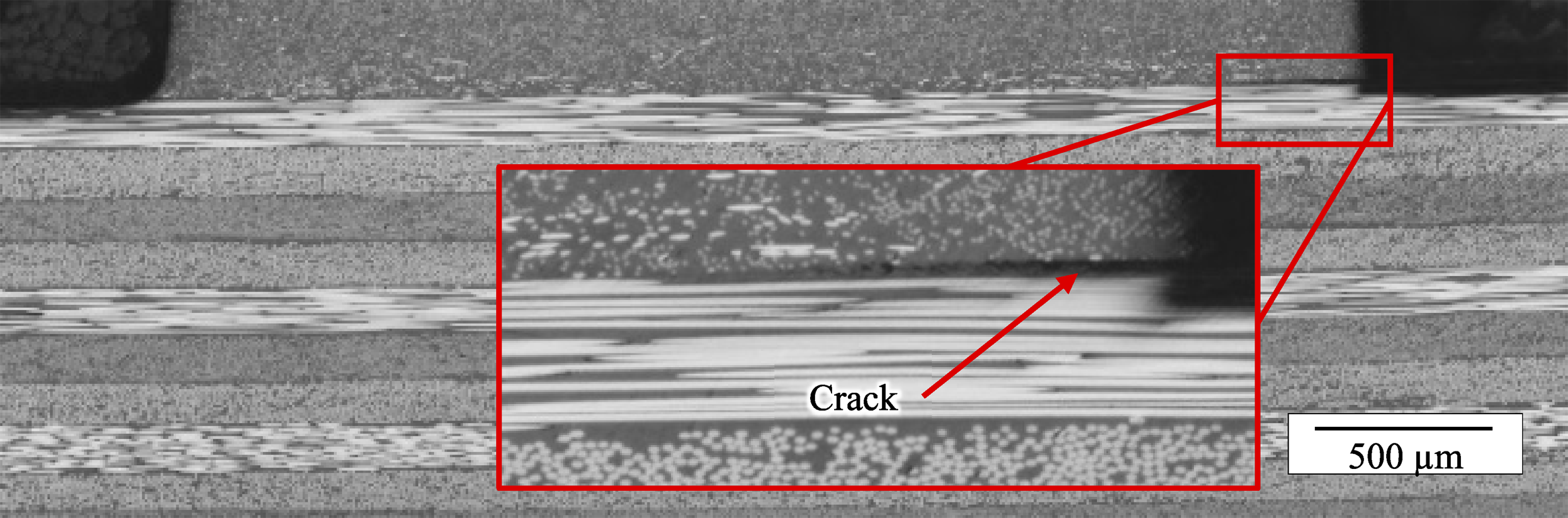
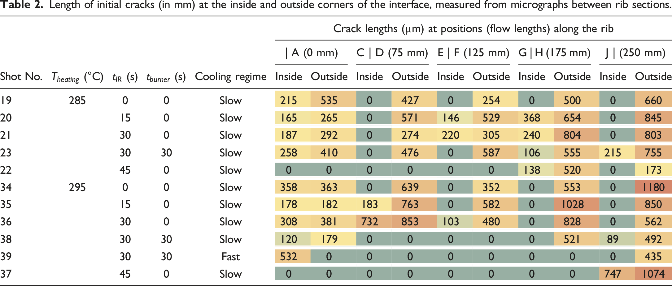
Some specimens had initial cracks at the interface, as can be seen in Figure 11 exemplarily. µCT scans revealed that these cracks did not originate from mechanical preparation of the cross section but were present further along the rib. The initial crack lengths, measured from the micrographs are summarised in Table 2. The colouring there is intended to aid the readers perception of trends. Despite the fact that only one specimen per position was analysed, three trends could be identified: 1. Inside versus outside corners: There are no or just shorter cracks at the inside corners, where the mould surface was up to 18 K hotter than at the outside corners. 2. Laminate surface temperature: Less cracks appeared for the higher laminate temperature (due to longer IR application) combined with higher mould temperature. While, for the cooler mould, 45 s of IR application (laminate surface was already molten) were required to eliminate most of the cracks, this was achieved with the 10 K hotter mould already after 30 s of IR heating. In the latter case, the laminate surface was not visibly molten. 3. Flow path length: The cracks seem to be generally longer near the flow path end, if present at all. Micrograph showing an initial crack. Length of initial cracks (in mm) at the inside and outside corners of the interface, measured from micrographs between rib sections.
From this, one could conclude that hotter moulds should avoid cracks better. But there must be another adverse effect. Considering only cases, where the laminate surface was not visibly molten, the correlation is apparent except for position A. There, at the inner corner, close to the gate (before position A), the steel was about 7 K hotter than at the inner corner far from the gate (after position J). But cracks appear at position A much more often than at position J. This could be a result of the melt flow dynamics. It is known that bent flow channels induce unsymmetric cross-sectional distributions of flow velocity, shear rates and finally the temperature due to viscous heating. 26 After entering the cavity through the gate from the inside, the melt has to make a left turn. The micrograph position |A is just after this turn and the melt flow velocity profile may have not developed symmetrically.
Boosting the mould temperature using the Bunsen burner appears to have little to no effect. At best it may have led to no crack at the inside between positions E and F for the lower mould temperature. This would be in accordance with the positive effect of mould temperature. However, it could also be that the locations of micrograph and the localised mould heating were not exactly matching.
Examining the fracture surfaces it is apparent that the initial cracks coincide with areas where the laminate surface just exhibits imprints of short fibres, but was clearly not molten completely. It is known that strong polymer joints can establish also if the substrate reached a temperature just between glass transition and melting temperature. But this so-called fusion bonding mechanism takes several orders of magnitude more time compared to completely molten substrates.18,27,28 Since in the overmoulding process the joint has to be formed in a matter of seconds or even less, complete melting is a prerequisite for substantial interdiffusion of the molecular chains. If interdiffusion and hence co-crystallisation remained incomplete, shrinkage of the injection moulded material leads to stresses in the joint which open the initial cracks by a few micrometres.
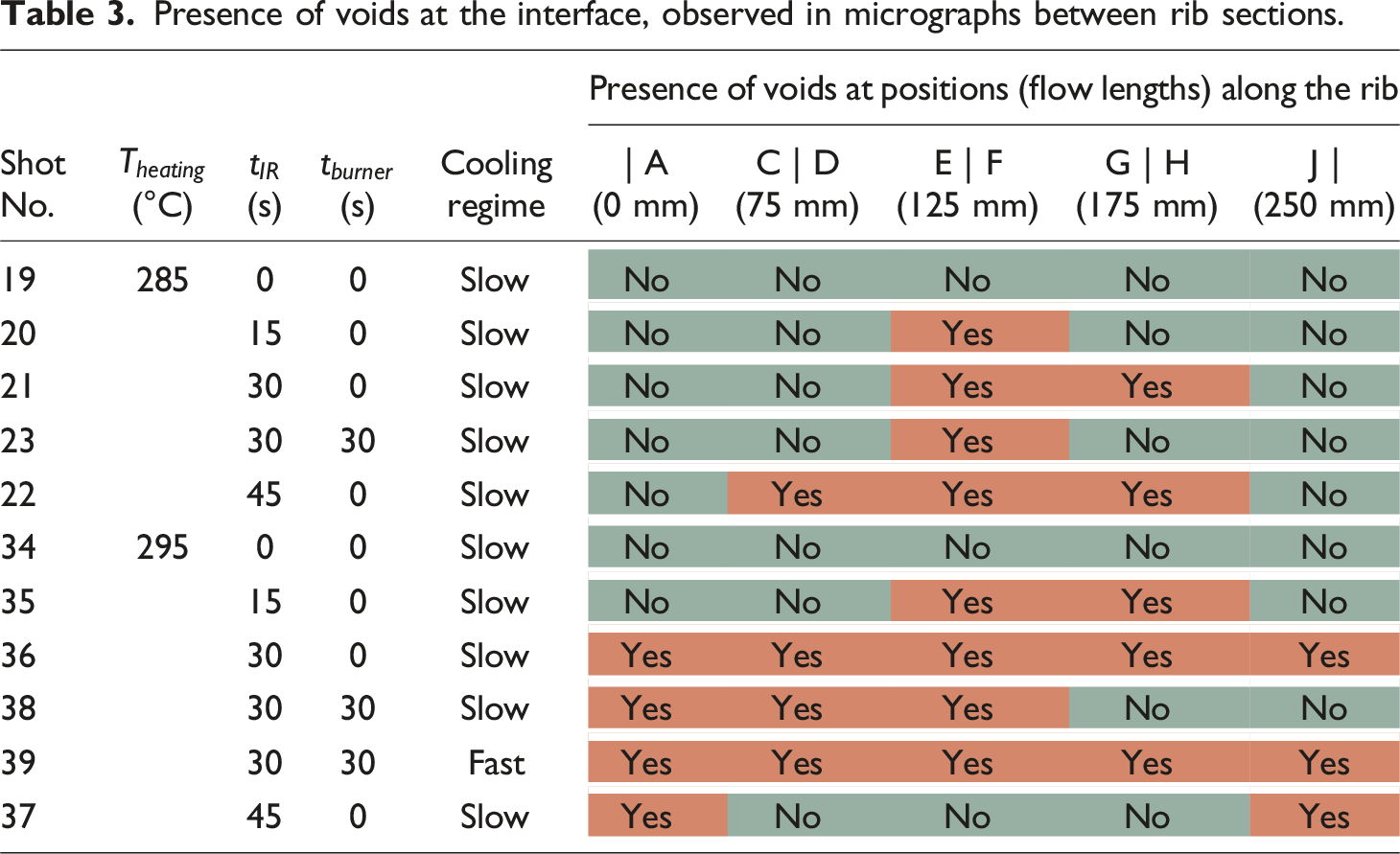
Interfacial Voids
Some micrographs show voids at the interface and within the first ply, see e.g. Figure 12. In contrast to the initial cracks, these appear rather in the centre of the cross section. The presence of voids was examined in all the micrographs and is summarised in Table 3. Two observations were made: 1. Effect of laminate temperature: Coupons to which the IR heater was not applied at all, had no voids. So, lower laminate temperatures seem to prevent voids. The higher the laminate was preheated by longer IR application, the more likely the voids formed. Interestingly, for the hotter mould, preheating the laminate until its surface melted ( Voids at the interface and within the first ply. Presence of voids at the interface, observed in micrographs between rib sections.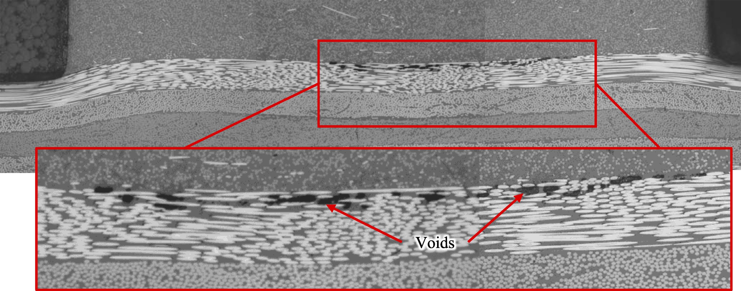
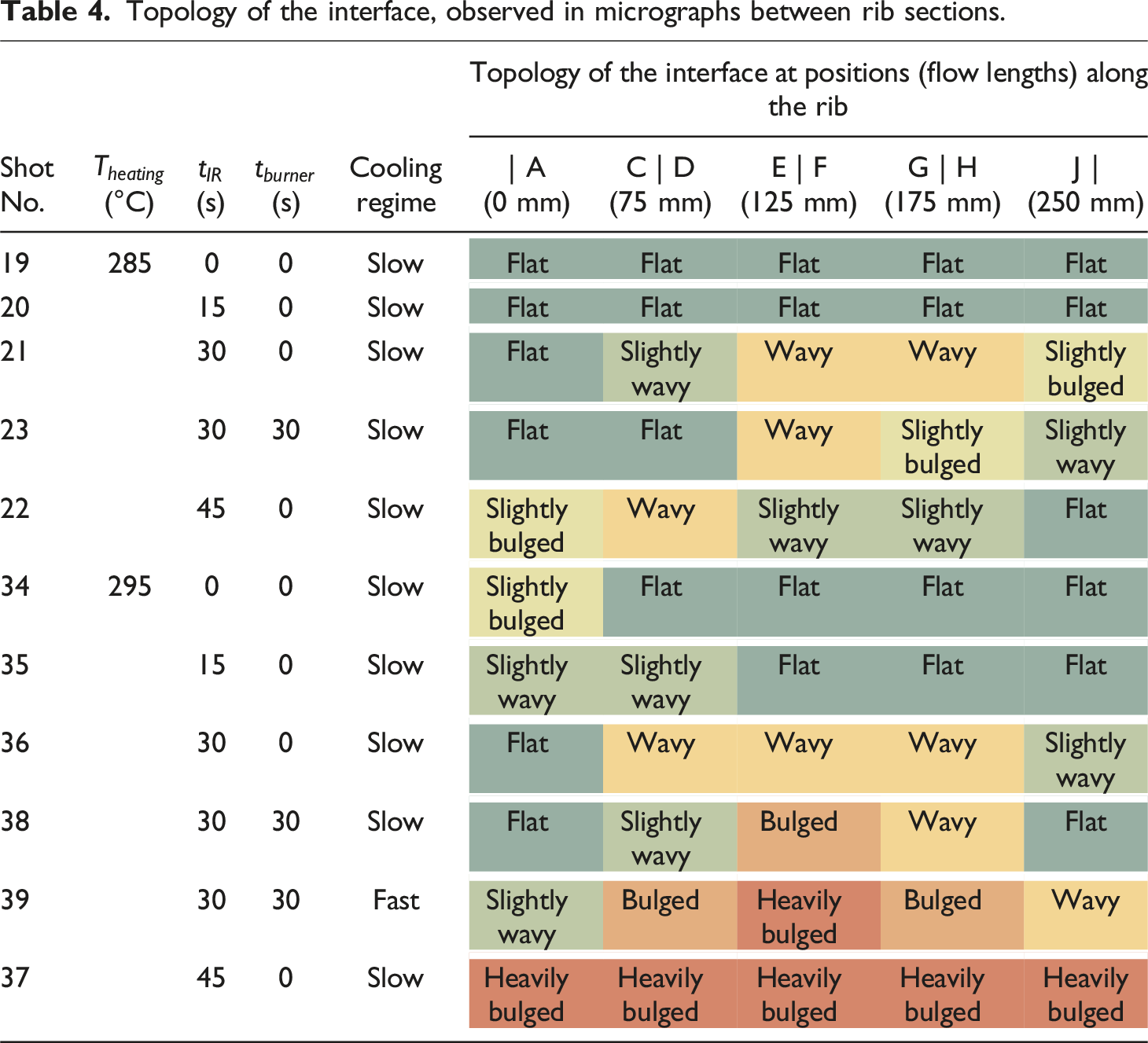
Laminate Deformation
Topology of the interface, observed in micrographs between rib sections.
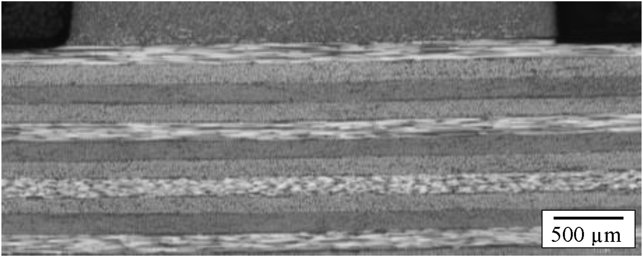
Example of a flat interface (shot 19, C | D, with
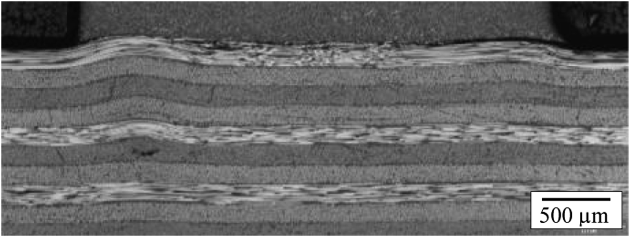
Example of a wavy interface (shot 21, G | H, with
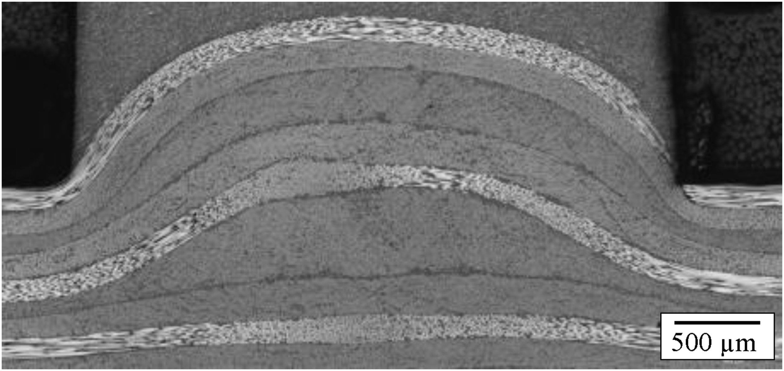
Example of a bulged interface (shot 37, C | D, with
A flat interface indicates that the laminate remained solid during overmoulding, i.e. it was not deeply molten. Wavy laminates seemed to experience some in-plane compressive stresses whilst being softened enough. Interestingly, some micrographs show transverse matrix cracks of the 0° plies, which exclusively but not always occurred when the interface was wavy. In bulged laminates it is apparent, that the 0° plies are much thicker under the bulge. This is due to excessive squeeze flow induced by the clamping force. It also indicates that the laminate was deeply molten. The internal pressure in the laminate was also sufficient to break the fibres of the 90° ply, as can be seen in Figure 15.
Fast cooling seems to have an effect, but such stronger deformation cannot have happened during cooling. So, this could be rather a result of the continuously rising mould temperature or just fluctuations of laminate preheating temperature.
Quasi-Static Pull-Off Tests
Quasi-static pull-off strength of selected rib sections from the preliminary trial.
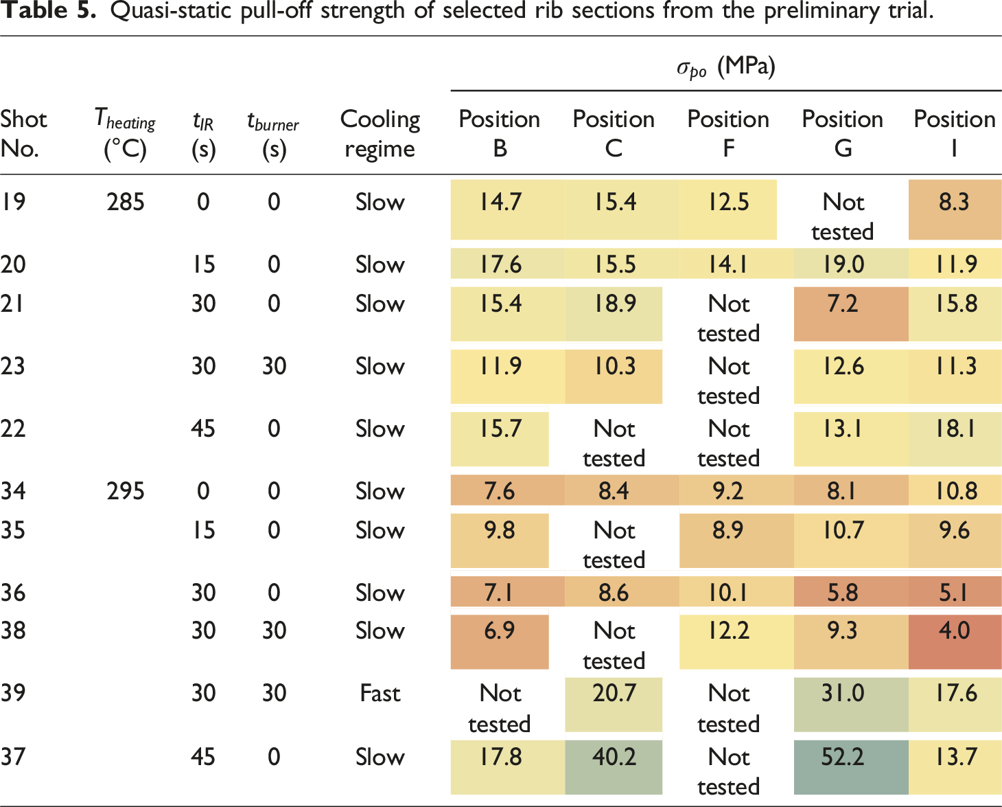
Remarkably high values were seen for shots No. 37 and 39. The fast cooled specimen (shot No. 39) showed much higher strength than No. 38, which had identical parameters but was cooled slowly. Since No. 39 showed also stronger laminate deformation it must have been at a higher preheating temperature and so the difference in strength cannot be attributed solely to the cooling regime.
Results of Main Experiments
Quasi-Static Pull-Off Tests
Figure 16 shows typical force-displacement curves. Characteristic are an often short, linear start-up phase, followed by a decreasing slope, which is presumably due to a settling movement of the wedge grippers. After that, the force increased again with the initial slope. Shortly before reaching the maximum force the slope decreased again, presumably due to crack growth. The maximum force was often associated with rapid rupture of most of the specimen. Typical force-displacement curves from quasi-static pull-off tests. (a) 0°. (b) 90°. (c) 0° with LMPAEK film. (d) 90° with LMPAEK film.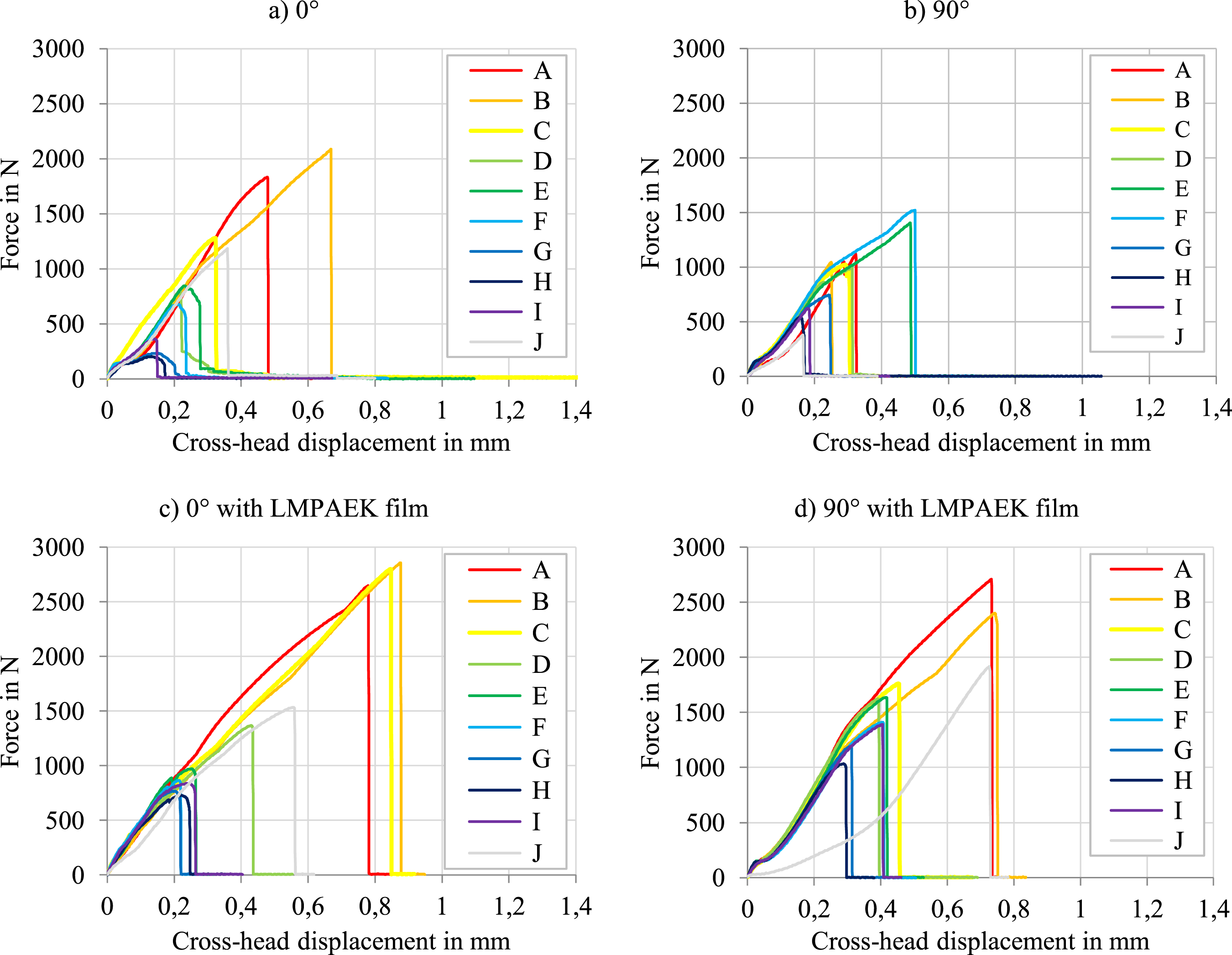
While most of the curves look similar in terms of shape, the maximum forces differ notably. It is apparent that positions A, B and C exhibited higher pull-off strengths than the others. Exceptions are sometimes the positions E and F for example of coupon number 19 and position J of all coupons with 90° laminate with LMPAEK film and 0° laminates without LMPAEK film. This is visible even better in Figure 17. There, the average values of all specimens with the same laminate configuration and position along the rib coupon are plotted versus the flow path length and the section number for clarity. Quasi-static pull-off strength versus position of the rib section.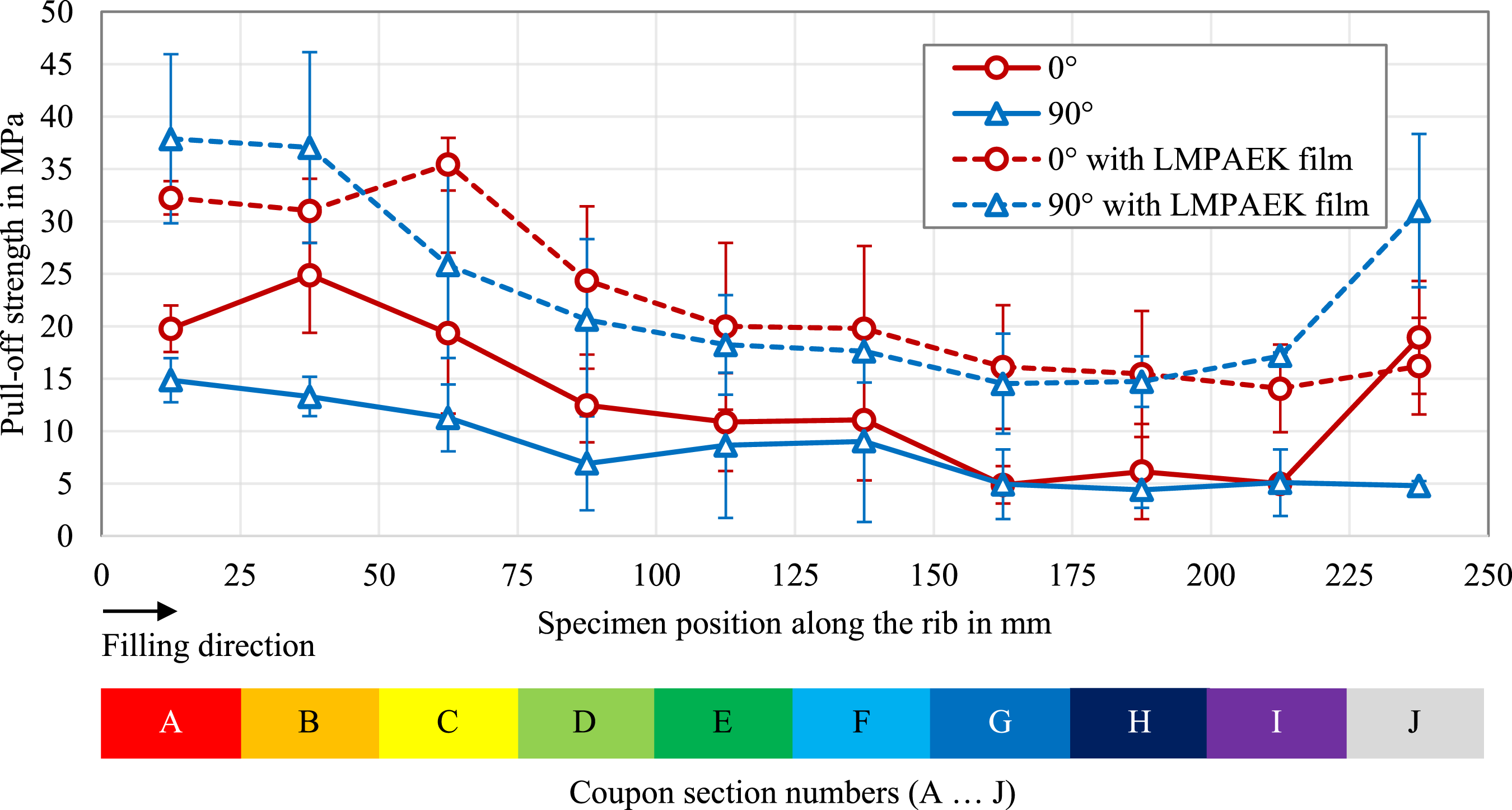
Results from quasi-static pull-off tests.
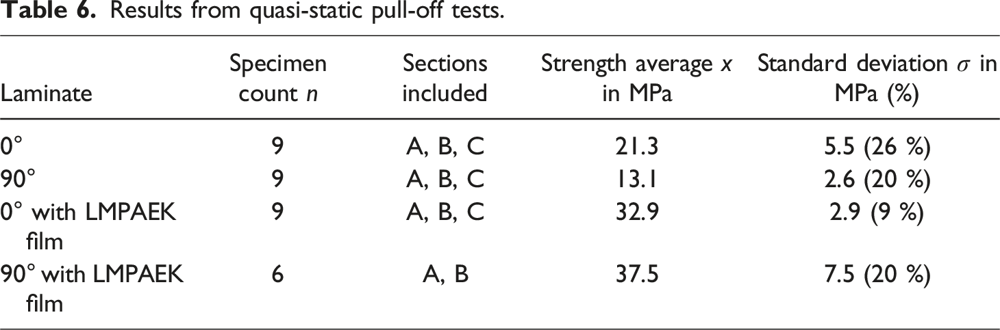
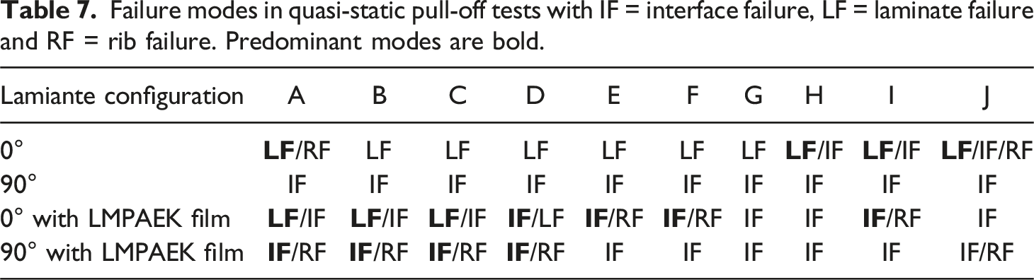
Failure modes in quasi-static pull-off tests with IF = interface failure, LF = laminate failure and RF = rib failure. Predominant modes are bold.
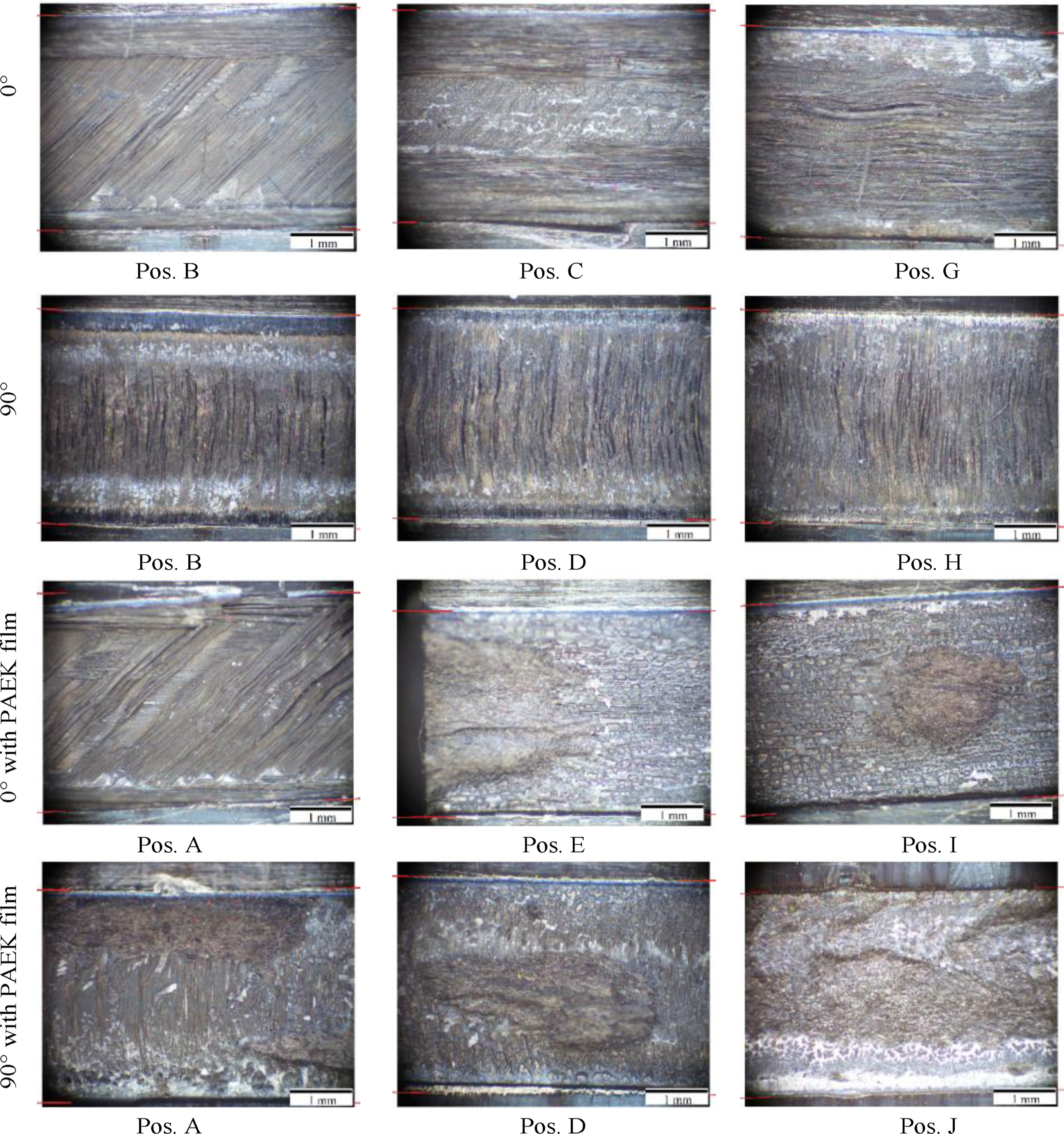
Representative images of fracture surfaces on the laminate side for all tested laminate configurations and selected positions along the rib. Red lines indicate the boundaries of the interface.
Apparently, there are distinct patterns depending on the location along the rib. Specimens at positions close to the gate with 0° laminates with and without LMPAEK film predominantly failed by delamination between first and second ply and, to a smaller extent, also in the first ply. Presumably, the crack is initiated in the corner edge between laminate and rib. Continuous fibre-reinforced material is often also found within the base of the rib because it flowed there due to the clamping force. So, the corner edge only consisted of laminate material and the corner acted as a notch, concentrating stresses transverse to the fibre. The transverse tensile strength of UD laminates is generally low and so the intralaminar matrix crack progressed deeper into the first ply. When it arrived at the interface to the 45° ply, it was deflected and continued to grow as a delamination towards the rib centre.
Further along the rib, the 0° specimens without LMPAEK film show less delamination between first and second ply while the portion of interface failure increases. Interestingly, the interfacial voids are visible as a cellular structure at the remaining delamination surface, so underneath the first ply.
With LMPAEK film, the 0° specimens failed predominantly the resin-rich interface layer. The voids covered the interface area almost completely. Nevertheless, there are remainders of injection moulding material still attached to laminate, see the positions E and I.
The 90° specimens without LMPAEK film separated completely through the interface but with a remarkable extent of intra-ply delamination and transverse cracks too. The path of crack growth could not be identified clearly. However, at the corner edges there is a band of very smooth laminate surface reaching about 200 µm to 300 µm into the rib centre. These are initial cracks, also observed in the micrographs. In 0° specimens these are much shorter in range of a few micrometres.
90° specimens with LMPAEK film failed mostly through the interface but also within the rib. Although the void content increased along the flow path, injection moulding material remained at the laminate here and there. As µCT-scans revealed, the interfacial voids sometimes do not cover the whole interface. Most probably, in these cases the crack is often diverted into the rib, leading to remainders of the rib material on the laminate. However, the mechanisms that determine the local changes of fracture mode should be investigated in future studies.
Results of the Fatigue Tests
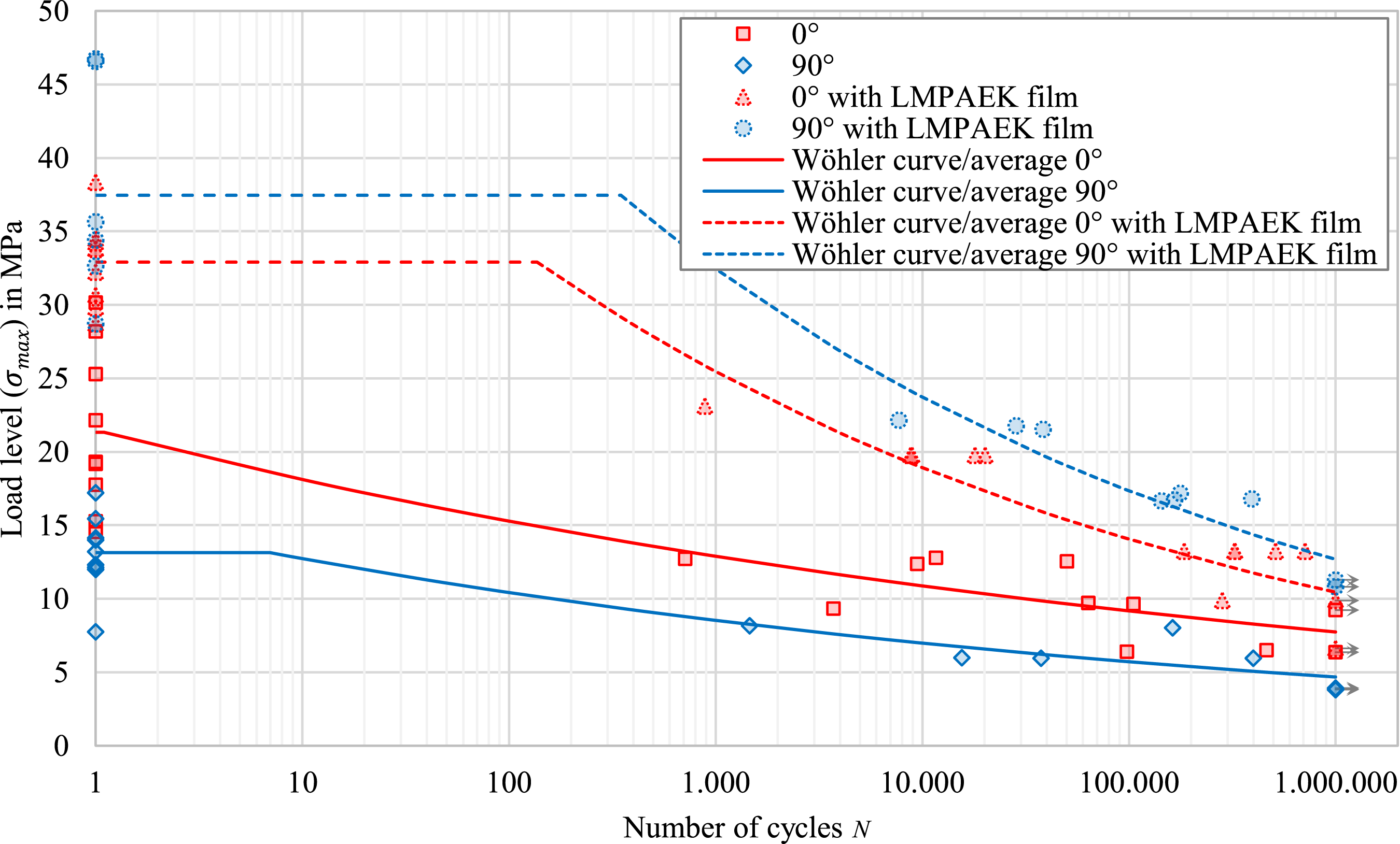
The S-N-plot in Figure 19 shows the results of the selected close-to gate sections which were tested under cyclic fatigue loading. Normal probability plots were used to identify outliers. These are plotted with grey symbols. The effects of LMPAEK film and fibre orientation as observed from quasi-static tests continued accordingly in the fatigue tests. Specimens with LMPAEK film survived longer at higher load levels. S-N-plot of the fatigue test results. Survivors are marked with an arrow, outliers plotted with grey symbols. For fitted Wöhler curves as well as a comparison of only the valid data points (without outliers) with the results from the monotonic, quasi-static tests, the reader is referred to Figure 28.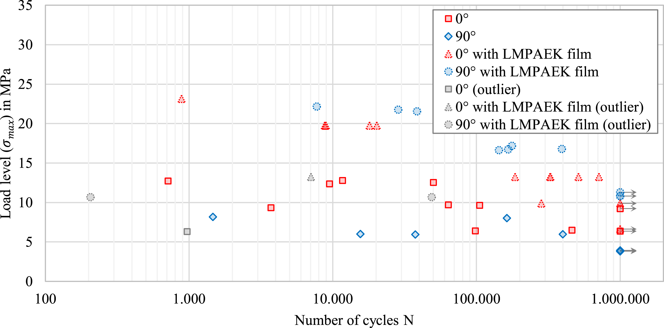
Similar to the quasi-static tests, fracture surfaces show a mixture of cohesive and substrate failure modes within the interface, the injection moulded material and the laminate. But in particular for 90° with LMPAEK film, it appears that the residues of short fibre-reinforced material are larger in fatigue specimens. When looking at the end faces of rib and laminate of these specimens, it is prominent that there is often a trapezoidal block in the centre of the cross section, adhering to the laminate. In the rib, there are often characteristic cracks, propagating from the upper corners of the trapeze. Figure 20 presents some examples. Remarkably, at the opposite end faces, fracture went just through the interface and no injection moulded material remained on the laminate. End faces of fatigue specimens (90° with LMPAEK film) where a larger, often trapezoidal block of injection moulded material remained at the laminate. The rib above shows characteristic cracks, propagating from the upper corners of the trapezoidal remainders.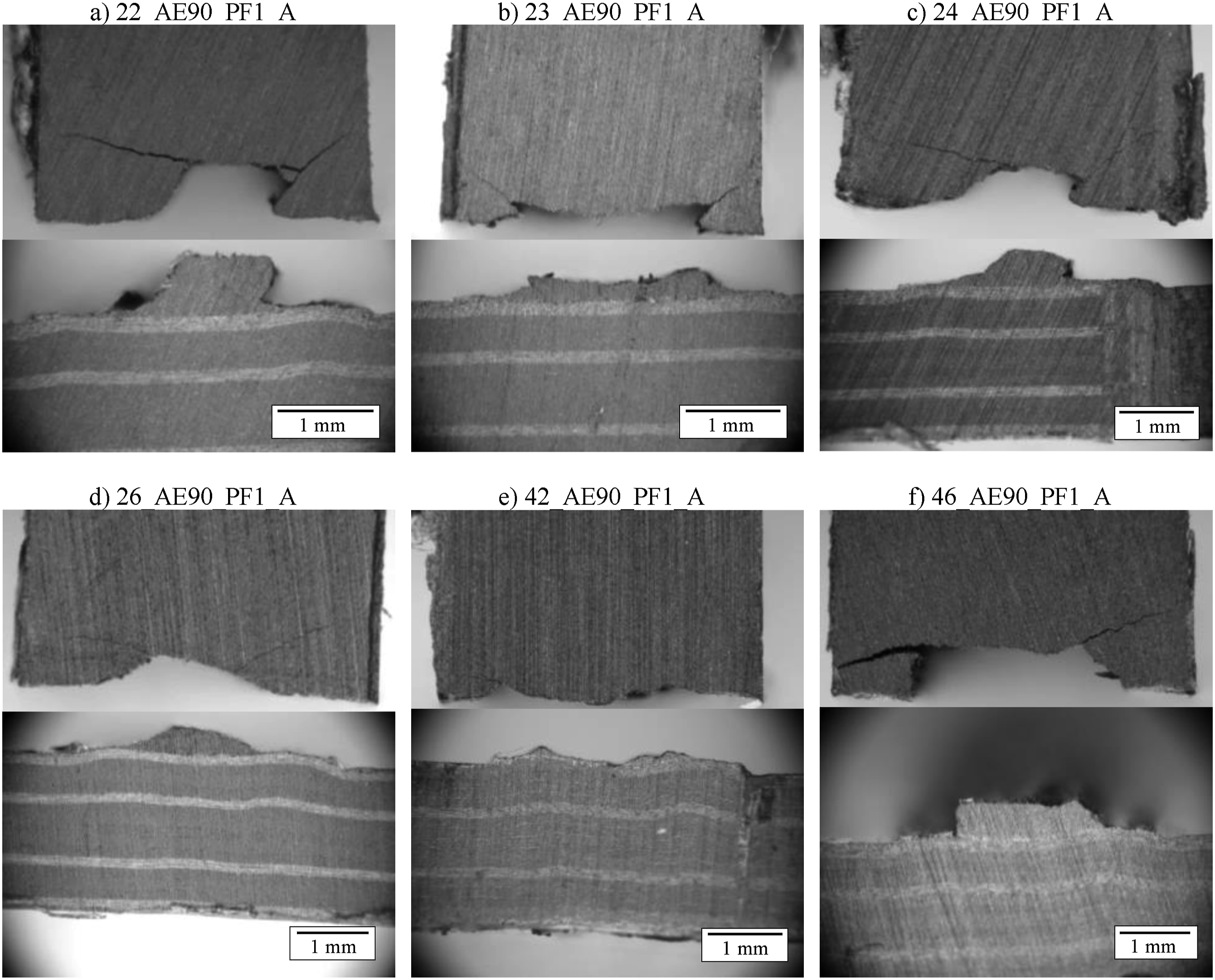
Discussion
Choice of Process Parameters Based on Preliminary Trial
Despite the low number of specimens and therefore not statistically secured results, the preliminary trial provided some indications. As the micrographs from the preliminary trial and the evaluated quality aspects show, the variation of processing parameters covered interesting combinations of process parameters. It seems that there are partly overlapping processing windows regarding the considered quality aspects. For avoiding initial cracks both the mould and laminate temperatures should be chosen rather high, where the laminate should be almost or already molten. Interfacial voids were observed more often at higher mould temperature and when the laminate was either not or very long exposed to the IR heater. The topology of the interface, i.e. whether it remained flat as the laminate surface or protruded into the rib, is clearly dependent on the laminate temperature. Obviously, longer exposure to the IR heater increases the laminate temperature, gradually melting and softening the matrix so that it can flow easier under the clamping force of the machine. In extreme situations which should occur also in the single-step process with completely molten laminates, the continuous fibres may be damaged if they run not parallel to the cavity contour, see Figure 15. In order to avoid this, the contour edges should be rounded.
Highest strength seemed to be achievable when the laminate bulged into the cavity. There were no voids and no initial cracks. This was the case for the centre sections of the coupon manufactured with the hotter mould and
In order to reduce the thermal gradient around the cavity, the mould was equipped with thermal insulation prior to the main experiment. Consequently, the temperature differences were reduced from up to 18 K to not more than 5 K.
LMPAEK Layer before and after Overmoulding
Figure 21 shows that LMPAEK from the additional 60 µm thick film partly migrated into the top ply during press consolidation. A clear interface between film and fibre-reinforced ply is hardly noticeable. Approximately 20 µm to 30 µm of the initial film thickness remained there without any continuous fibres. After overmoulding, micrographs of the interface in Figure 21 indicate that the resin-rich layer further decreases as short fibres are dispersed as close as a few times the fibre diameter of around 6 µm. Micrographs of laminates and overmoulded interfaces (dashed lines) without and with additional LMPAEK-film.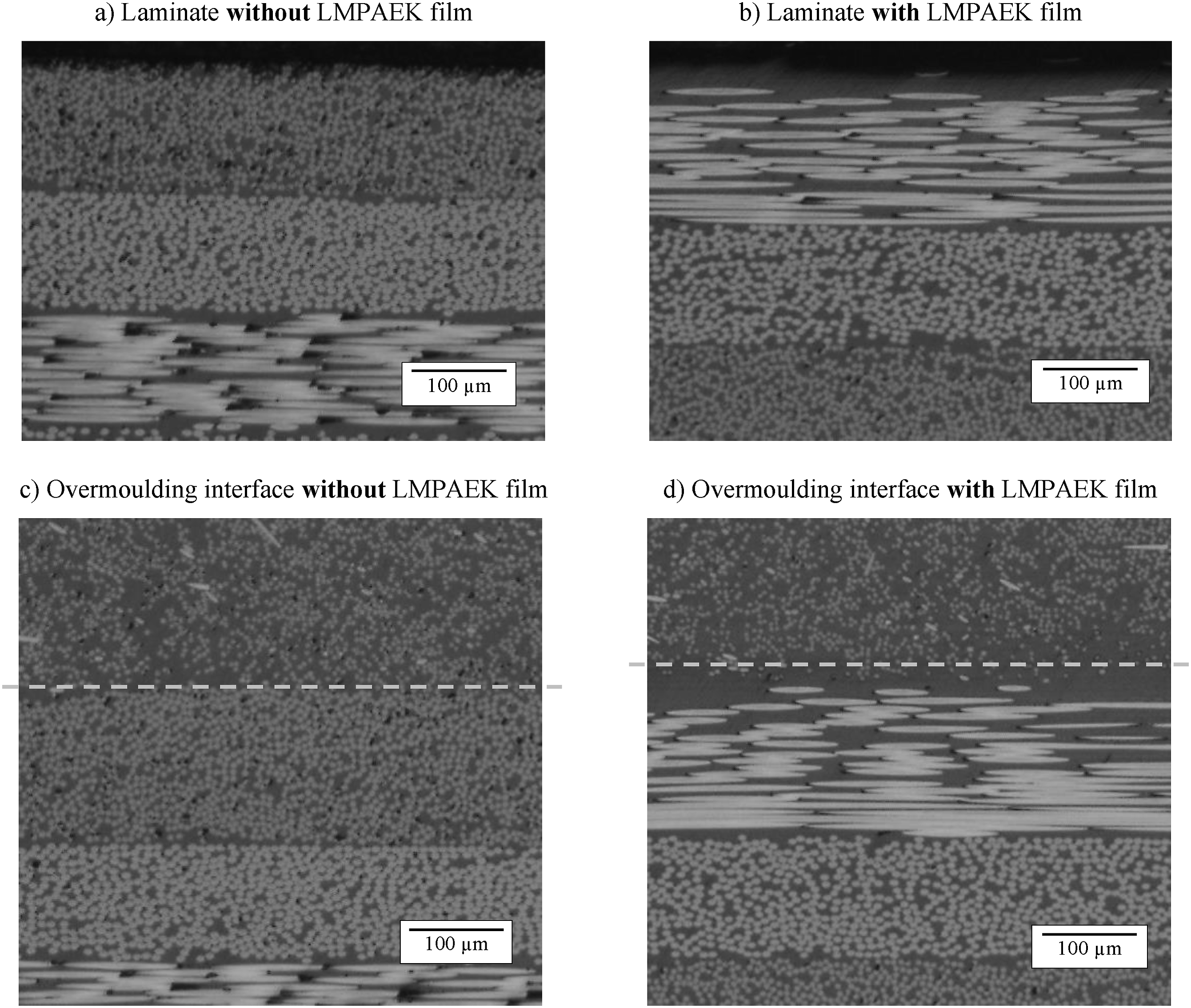
Whether there is a distinct separation or a gradual blend of LMPAEK and PEEK cannot be concluded using optical microscopy. However, it seems that the injection moulded material replaced some LMPAEK from the laminate surface. Another experiment which is not further described here, shows that this wash-out effect can occur. There, a black coloured laminate made from woven glass fibre-reinforced polypropylene (PP) was overmoulded with a short glass fibre-filled PP. The coupon was designed so that the melt overflowed the laminate and continued to fill the cavity beyond the laminate’s edge. From Figure 22 it is evident that some of the black-coloured laminate polymer was washed out and carried away for several millimetres by the natural-coloured moulding compound. Black-coloured PP, washed out from a laminate by the overflowing natural coloured PP melt.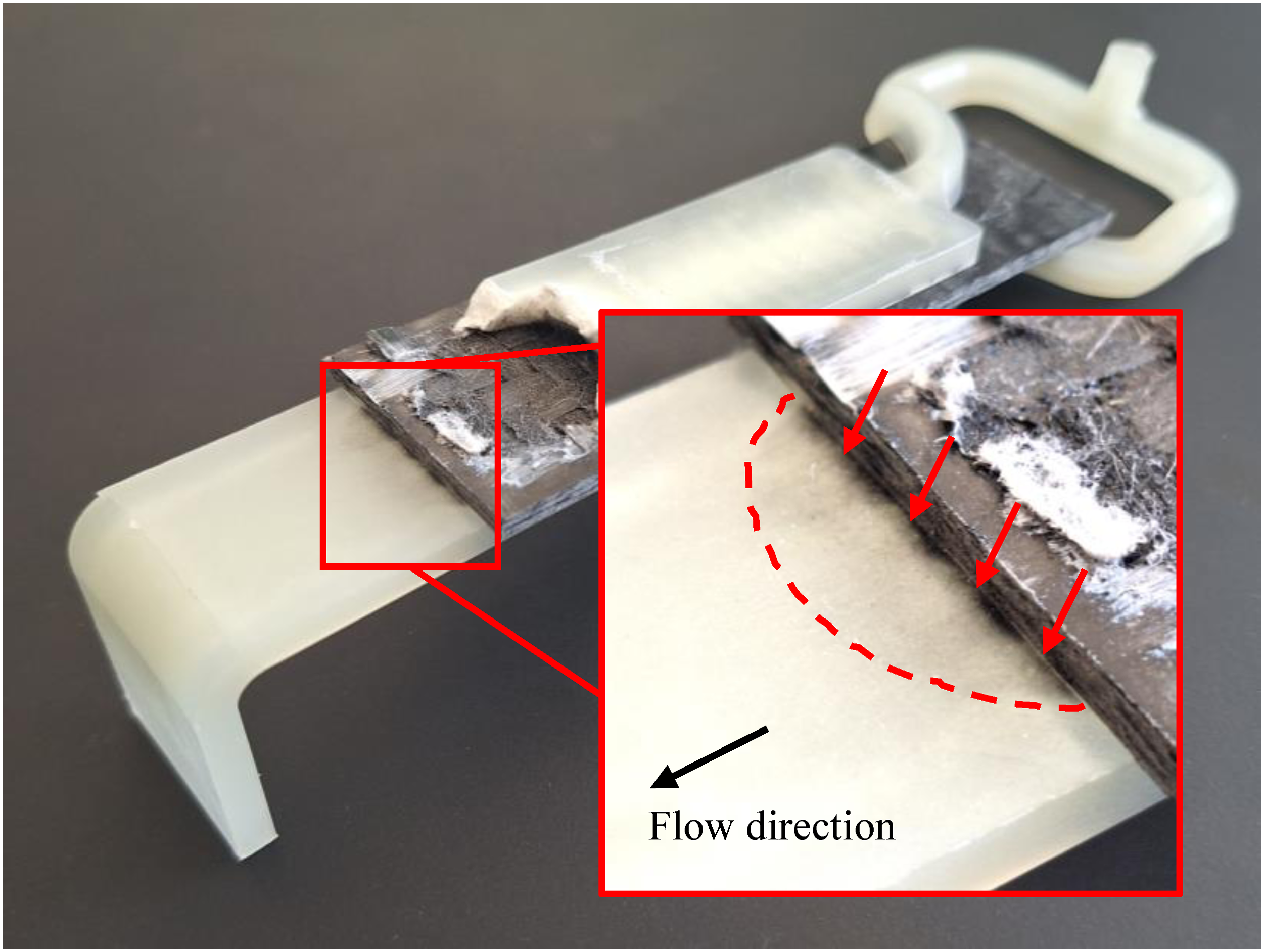
In yet another experiment with a similar rib coupon to the ones used here, made also from 90HMF40 but a woven carbon fibre-reinforced LMPAEK laminate, such wash-out phenomenon was observed too. Figure 23 shows how the resin-rich pockets within the woven fabric laminate surface are replaced increasingly towards the centre of the rib, indicating a wash-out of polymer from the laminate.
29
Cross sectional micrograph of another rib coupon. The resin-rich pockets within the woven fabric laminate surface are replaced increasingly towards the centre of the rib, indicating a wash-out of polymer from the laminate.
29
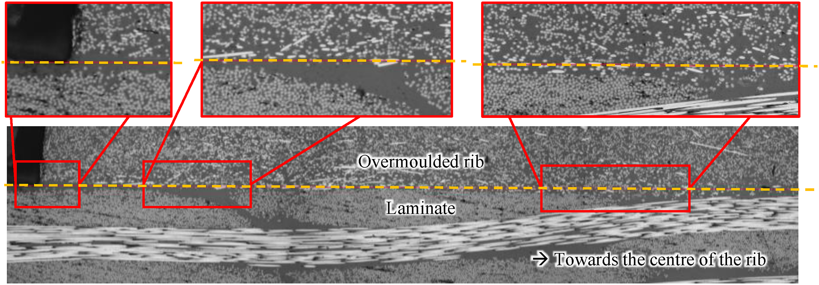
Both examples show that the extent to which laminates are washed out depends on the temperatures and melt flows. Hence, part designs and gate positionings inducing a long-lasting overflow of larger areas could erode resin-rich surfaces. Consequently, findings on the effects of resin-rich layers on joint strength should be applied with care to other components.
Effect of the Flow Path Length
A dependency of the pull-off strength on the flow path length could be expected based on the literature because melt flow and hence the thermal situation can vary locally and eventually lead to varying degrees of melting, healing and trans-crystalline morphology. For example, Donderwinkel et al. 18 reported a decreasing strength close to the flow path end, while Geyer et al. 30 observed a reduction already much closer to the gate. Indeed, in our study, the pull-off strength varied with the distance from the gate. High values of quasi-static pull-off strength were observed near the gate and in some cases also near the flow path end. The other positions are weaker, most likely due to the more intense void phenomenon there. Hence, variation of the degree of healing along the flow path is not the only driver for flow path length dependent joint strength.
A numerical injection moulding simulation using the Moldex3D software
31
was conducted to obtain pressure and temperature histories for several locations along the rib. The results in Figure 24 show that the packing pressure was effective for up to 2 s longer at the positions closer to the gate. Interestingly, the temperature history at the interface is almost equal except for positions 1 and 8, which are the beginning and end of the rib respectively. There, the temperature is up to 5 K higher, while the other positions have more or less the same temperature. The difference can be explained by the dome features at each end of the rib, which were intentionally placed there to homogenise the flow front. Since more melt is accumulated there, it takes longer to cool. Hence the adjacent positions 1 and 8 remain hotter for longer. Simulated pressure and temperature histories at sprue and interface.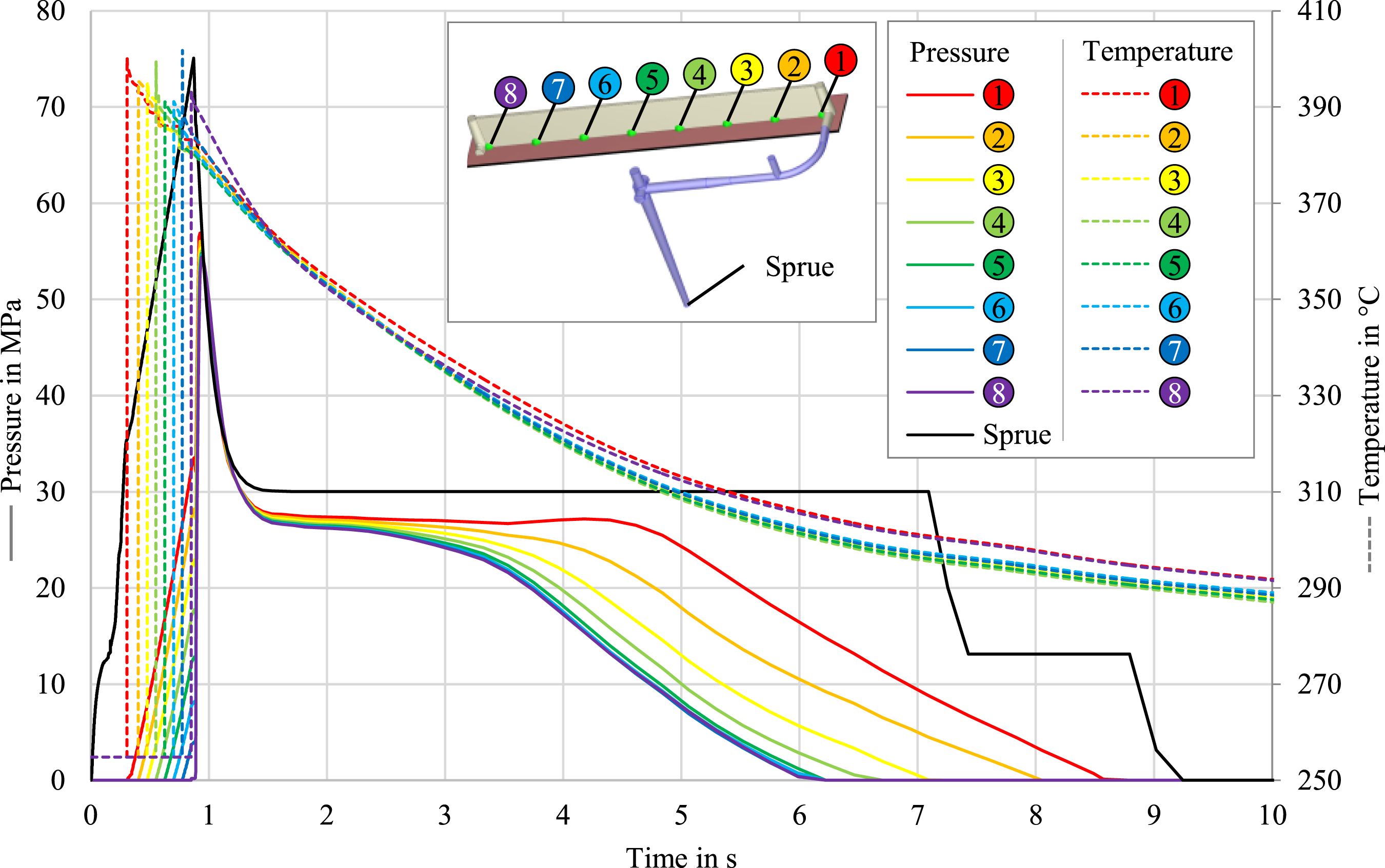
Interfacial Voids Phenomenon
The fracture surfaces exhibited a distinct void pattern at or close to the interface. As can be seen from Figures 18 and 25, the void density can be very high, covering most of the interface area. To our knowledge, such foam-like structures at some of the fracture surfaces on overmoulded composites have not been described in the literature yet. Close-up of a fracture surface (laminate side of specimen 16_AE0_PF1_F). Clearly visible is the cellular structure of the interfacial void layer on top of the continuous fibres.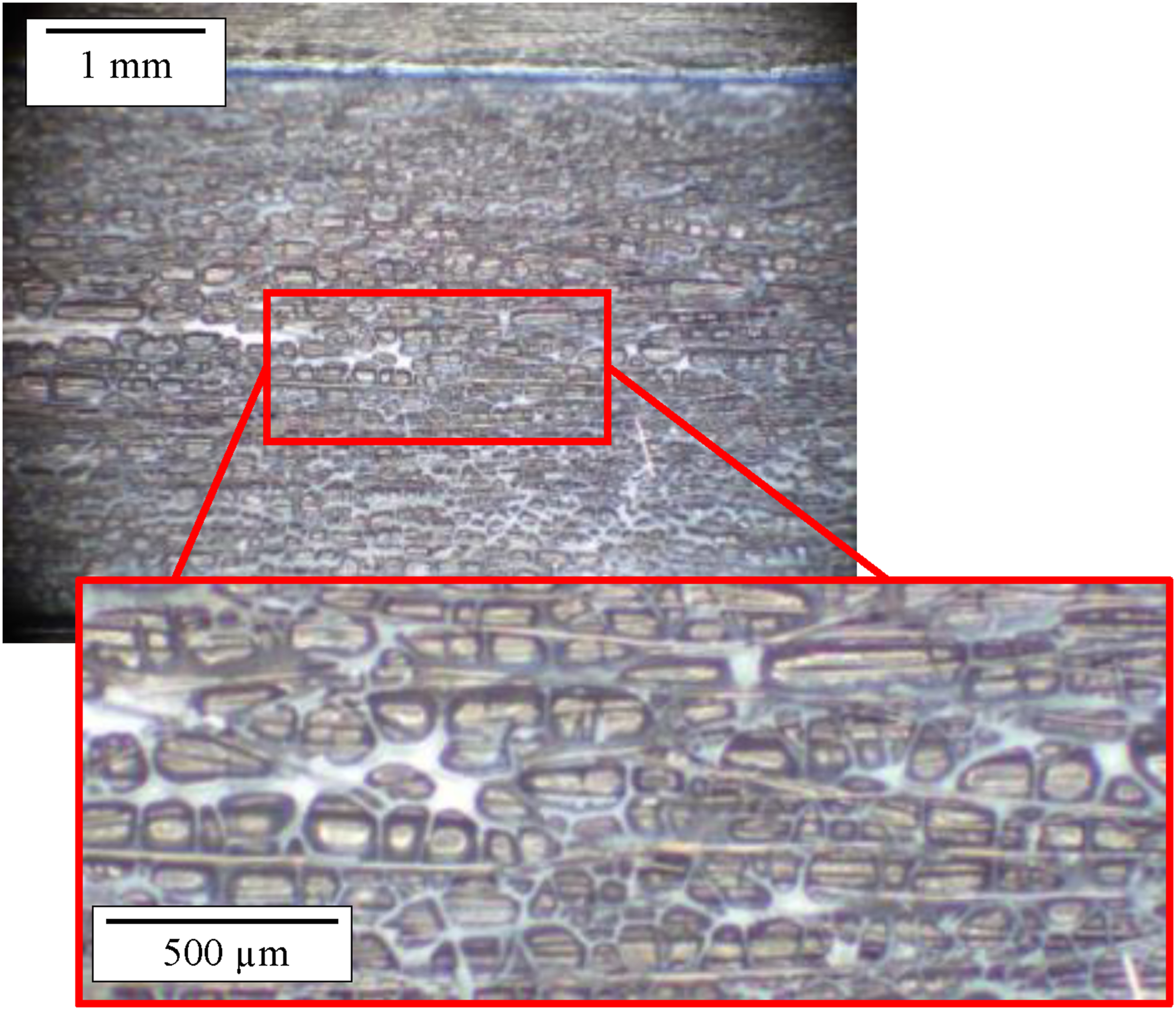
For the void formation process, we propose the following hypothesis. In traditional injection moulding, internal voids result from uncompensated shrinkage. 32 When component or runner are partly frozen, a molten core remains being cut off from the sprue. The material continues to shrink as it cools. But shrinkage of the molten core is hindered by the solidified surrounding material. When its internal pressure decreased close to zero, bubbles can grow within the melt which are filled with vacuum, previously dissolved gas or even water vapor. In the overmoulding coupon, we assume to have a similar situation especially at the interface. The chosen combination of PEEK and LMPAEK may be contributing to the void phenomenon. The LMPAEK polymer not only melts at lower temperatures than PEEK, also it solidifies at lower temperature. During dual-step overmoulding, the PEEK transfers additional heat into the preheated laminate, leading to a thin molten layer. When the PEEK then cools and solidifies, there may be a situation in which the interface lies within the molten core region. If then the packing pressure does not effectively compensate for the shrinkage of the laminate because the rib or the runner are frozen already, the pores begin to form and grow until the molten core is also frozen.
This would also explain the observed effects from the preliminary trial with one exception. For
The observed effect of higher mould temperature leading to more voids can be explained less clearly. A colder mould could lead to a smaller molten core at the interface which solidifies early enough before the packing pressure is cut off. On the other hand, part and runner should freeze earlier due to the cooler mould.
The injection moulding simulation results support the assumption that local packing pressure history is determinant for the interface voids. When comparing Figures 17, 18 and 24, it is noticeable that the positions with packing pressure acting for longer correlate with those showing higher pull-off strengths and less interfacial voids. However, advanced injection moulding simulations including a more complex material model being capable of accurately predicting compressible material flow, anisotropic viscosity, anisotropic thermal conductivity and squeeze flow as well as phase changes and viscoelasticity could help to predict the likelihood of void formation for any overmoulded component accurately.
Effect of a Resin-Rich Interface Layer
As discussed above, the PEEK/LMPAEK material combination might be more sensitive to insufficient packing pressure than PEEK-PEEK overmouldings. However, although the void phenomenon is more pronounced in specimens with LMPAEK film and although these reduce the cross section, specimens with additional LMPAEK film show significantly higher rib pull-off strengths than those without. Comparing the fracture surfaces in Figure 18, partial substrate failure of the rib occurred rather for specimens with additional LMPAEK film. Analogous to adhesive bonds, there could be an optimum thickness of the polymer interlayer, which results in maximum interface strength.
Effect of Fibre Orientation
The effect of the top-ply orientation with respect to the rib on the pull-off strength is significant only for specimens without additional LMPAEK film and rather close to the gate. In these cases, 0° specimens show higher strengths. The crack typically grows into the 0° ply until it arrives at the 45° ply where it is deflected and continues as a delamination. In some cases, the specimen end faces showed also deeper fracture down to the third ply, see Figure 26. However, this is considered to be an effect of the end face where all 0° and 45° fibres are interrupted. The farther the 0° specimens are from the gate, the more predominantly they fail in the interface before the crack turns into the laminate. Close-up of the front face of the laminate after rib pull-off (0° specimen, position C). The first ply (0°) is almost completed ripped off and rupture progressed throughout the second ply (−45°) and even the third ply (90°) partly delaminated.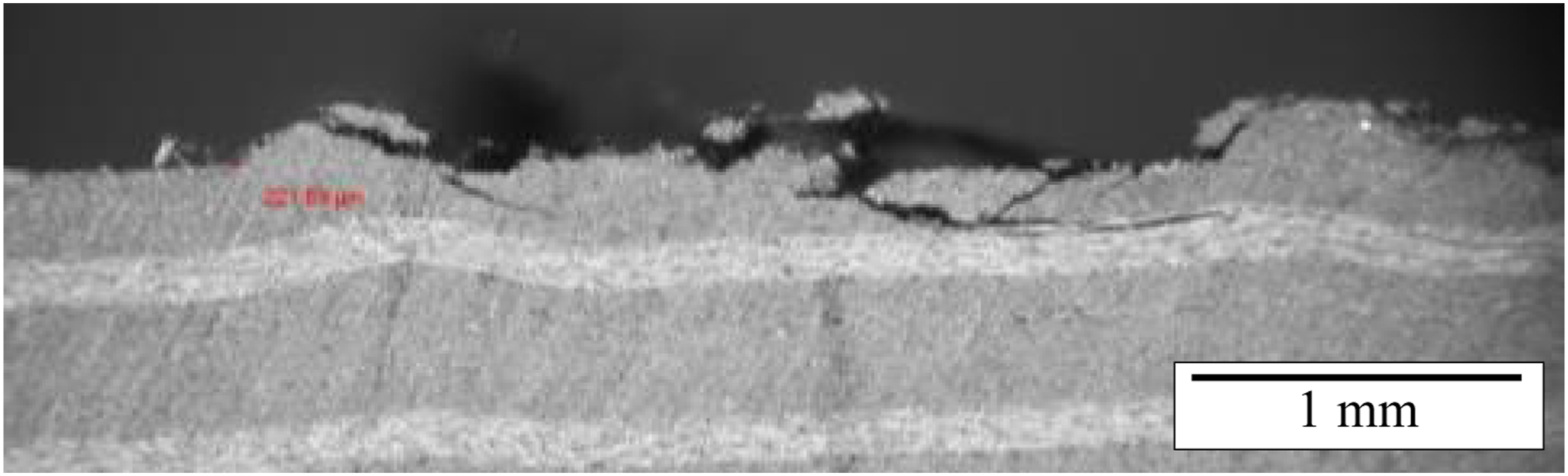
Crack initiation in 0° specimens takes place in two different modes. If the interface remined flat enough the crack initiates at the interface close to the corner edge. If more laminate material was displaced into the rib cavity, the cracks initiates in the corner edge within the 0° ply.
90° specimens, regardless of the LMPAEK film, exhibit some inter-fibre damage but never broken continuous fibres so that the fracture is forced to stay above the top ply. With LMPAEK film the amount of remaining injection moulded material on the laminate is much higher.
In 90° specimens the interface cannot move away from the corner edges which is probably why failure is always initiated there. But of course, initial cracks are also located there and are larger for 90° than for 0° specimens. Figure 27 shows typical initial cracks for the four tested laminate configurations. Initial cracks are likely to occur at the interface if the laminate is too cold to melt when the injected compound touches it. We hypothesize that a layer of interfacial voids provides a greater compliance in the normal direction. When materials cool and shrink then, this layer relaxes stresses so that initial cracks could be reduced. Besides, the resin-rich layer actually is a good thermal insulation, reducing the heat loss of the laminate to the cooler mould. This is particularly beneficial when the outer ply runs perpendicular to the rib. Due to the higher thermal conductivity in fibre direction, greater heat loss to the mould means a higher risk of incomplete melting, interdiffusion and healing. Accordingly, with an additional LMPAEK layer, initial cracks are greatly reduced at the corner edges of specimens with a 90° top ply, see Figure 18. Typical initial crack patterns for the four tested laminate configurations.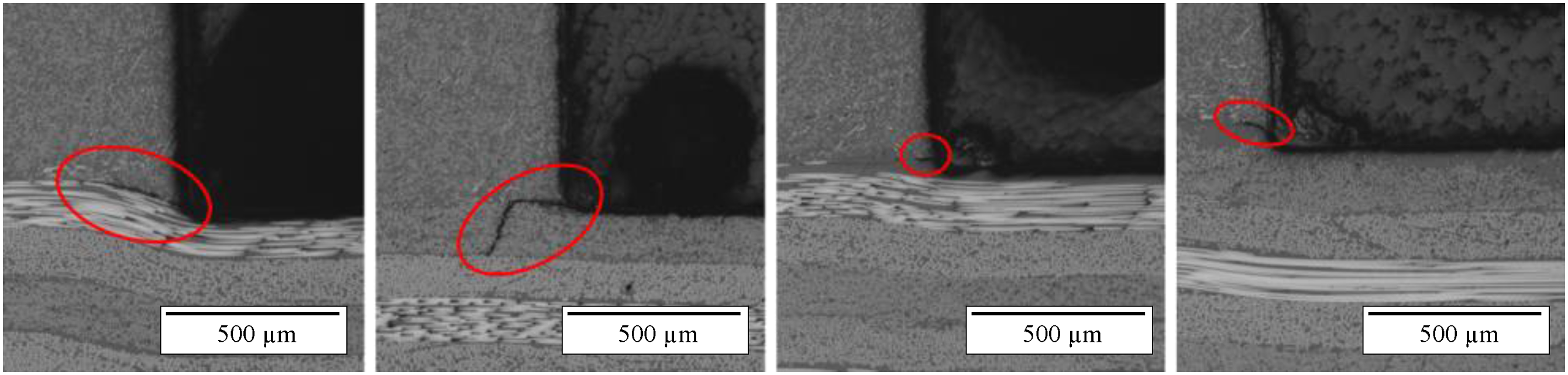
It would be interesting to study the crack initiation and growth in micro-scale simulations or in situ µCT scans under applied load. Also, the effect of short fibre orientation may play a role which should be investigated further using advanced simulations in future studies.
Failure Behaviour under Cyclic Fatigue Loading
The failure mechanisms under cyclic loading appear to be similar. For 90° specimens there is a noticeable difference. The fracture surfaces show the usual initial cracks, which presumably grow at first similar to the quasi-static tests. At some point however, the short fibre-reinforced material must have taken more damage under cyclic loading and the crack was diverted earlier into the rib so that larger portions of it remained on the laminate. We hypothesize that this has to do with the short fibre-reinforcement. Stresses are concentrated locally around the numerous fibre ends. Perhaps more micro cracks develop from there under cyclic loading. If such micro cracks occur in the vicinity of the interfacial crack tip, the crack rather grows into the rib. The orientation of short fibres depends on the melt flow kinetics. In micrographs of the rib cross section, one can clearly see that higher orientation occurs parallel to the cavity walls and the interface. Thus except for the symmetry plane of the rib, the plane of higher orientation is inclined with respect to the laminate, providing a potential preferred path for crack growth. In accordance with this theory, the characteristic cracks observed in the rib in Figure 20 run more or less parallel to the higher oriented short fibres. Consequently, the short fibre orientation should be studied in more detail in future studies on fatigue of overmoulded components. Potentially this could lead to more precise predictions of fatigue strength.
As stated, probably the initial cracks at the corner edges between rib and laminate grow at first towards the rib’s symmetry plane. Since one end face of 90° specimens shows larger residues of injection moulded material and the opposite face does not, the direction of crack growth probably changes over the course of the fatigue test. Unfortunately, it cannot be conclusively told from the observations how it went exactly.
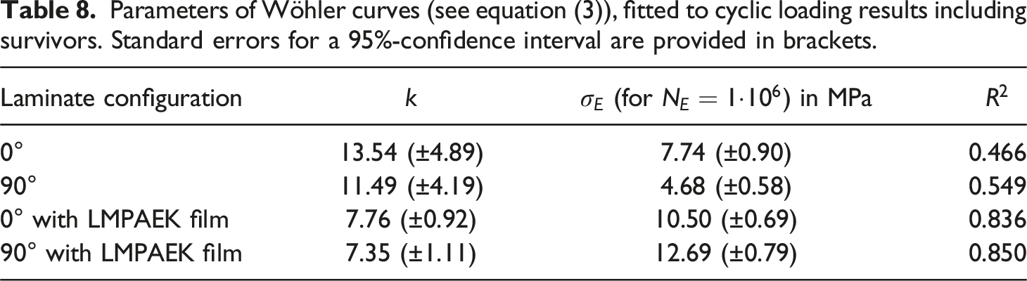
Apart from investigating the fracture behaviour, the experiment aimed at obtaining a first impression of the general fatigue strength for several load levels. The fatigue behaviour of many materials can be described by a Wöhler curve which, plotted in a common S-N-plot, is defined as: Results of the cyclic fatigue tests with fitted Wöhler curves, intersected with the average pull-off strengths from the quasistatic, monotonic tests at Parameters of Wöhler curves (see equation (3)), fitted to cyclic loading results including survivors. Standard errors for a 95%-confidence interval are provided in brackets.
Dual-step versus Single-step Processes
There are clearly some challenges inherent to the dual-step overmoulding process studied here. But locally higher heating of the laminate could help to resolve the cold spots and sub-optimal weld formation in the dual-step process. Similarly, differential mould tempering with hotter spots around the interface could be considered.
In the single-step process, excessive migration of laminate material into the cavity is very likely to occur, given that most of it is still viscous when the clamping force is established. It is debateable whether higher pull-off strengths observed after the single-step process originate from a kind of mechanical interlocking, a larger interface area15,34 or even a different, eventually stronger, trans-crystalline structure.35,36 Interestingly, Stegelmann et al. 34 reported that, for some materials processed in single-step overmoulding, a thin layer of matrix polymer can be squeezed out of the laminate and speculated whether this is responsible for lower pull-off strength. Such effect is more likely for woven laminate material rather than unidirectional tapes and when the fibre volume content is not too high.
The observed interfacial voids can also form in the single-step process. Although neither mentioned nor discussed in their study, Valverde et al. 16 showed a micrograph of a similar rib coupon which was made using the single-step process and exhibits voids right at the interface. Since they used carbon fibre-reinforced PPS material, this also proves that the interfacial voids are not exclusively occurring for combinations of polymers with different melting temperature.
Evaluation of the Simple Injection Mould Concept
The concept of dual-step overmoulding using a mould, designed as simple as possible, without an oil tempering system and simple cold runners was investigated. Although it would be desirable to waive on the oil tempering and on a hot runner system, we conclude that both are strongly recommended for processing carbon fibre-reinforced high-performance thermoplastics. Such material is quite sensitive to inhomogeneous mould temperature, especially in the dual-step process.
Conclusions
Rib coupons were overmoulded in the dual-step process and sections of these were tested under quasi-static and cyclic pull-off loads to investigate the effects of a matrix rich interlayer and the orientation of the adjacent unidirectional ply. A preliminary experiment was conducted to investigate effects of process parameters on the coupon quality and pull-off strength.
The orientation of the first ply with respect to the filling direction showed a significant effect, when no additional LMPAEK-rich layer was present at the laminate surface. Specimens with the ply oriented parallel to the rib showed more than 60% higher pull-off strength compared to 90°-specimens. This was attributed to predominant substrate failure within the laminate in the 0° configuration.
A resin-rich surface layer was achieved by adding a polymer film to the stacking prior to hot press consolidation. The resultant layer thickness had less than half of the film thickness due to migration of continuous fibres into the film. The resin-rich layer increased the pull-off strength significantly under both quasi-static and cyclic fatigue loading. It also equalised the effect of first ply orientation. However, interfacial voids were more pronounced if there was a resin-rich layer.
To our knowledge, the observed interfacial void phenomenon has not been reported and discussed before. According to our hypothesis it originates from a prematurely frozen runner and the consequent cut-off from packing pressure before the joint is frozen. The combination of PEEK and LMPAEK polymers with different freeze temperatures and rather increases the probability of such voids presumably. With a hot runner system and advanced mould temperature control the voids should be avoidable. From the preliminary trial it can be concluded that a deeply or even completely molten laminate (as in the single-step process) could help to avoid the interfacial voids. The mechanism behind is that the normal pressure on the laminate due to clamping force of the injection moulding machine can be distributed within the laminate as a hydrostatic pressure as long as the laminate is molten. Then, even if the injection moulding material freezes and packing pressure is no more acting sufficiently at the interface, the hydrostatic pressure within the laminate can act as a substitute packing pressure and counteract void formation.
As far as we know, the fatigue behaviour of PEEK/LMPAEK overmouldings was also investigated for the first time. As expected, the pull-off strength decreased under a cyclic fatigue loading. Due to the void phenomenon only the first two or three specimens of each coupon could be tested. This reduced the number of specimens and only one load ratio of R = 0.1 was tested. Despite the large scatter, simple Wöhler curves were fitted, illustrating the distinct effects of a resin-rich laminate surface and the fibre orientation. However, further investigations are necessary to find out whether an endurance limit exists and how overmoulded joints behave under different load ratios. Also, the effect of initial cracks and the course of crack growth are to be investigated further.
In this study, we followed the concept of dual-step overmoulding using a mould, being designed as simple as possible, without an oil tempering system and with just simple cold runners was investigated. Although it would be desirable to waive on the oil tempering and on a hot runner system, we conclude that both are strongly recommended for processing carbon fibre-reinforced high-performance thermoplastics.
The dual-step process clearly conserves the quality of the laminate part better. Laminate material migrates less into the cavity compared to the single-step process. Consequently, local deviations of fibre orientation are greatly reduced. However, the risk of cold spots at the corner edges is higher in the dual-step process because the laminate brings less heat into the joint. This can lead to locally incomplete melting, interdiffusion and co-crystallisation, leading to a weaker bond or even initial cracks. Locally adapted heating of the laminate and or locally higher mould temperature could help to resolve such problems.
Numerical simulations of the manufacturing process could help to optimise processing parameters, part and mould design and to better understand the mechanisms in the material. Especially accurate predictions of laminate deformation, interfacial void formation and fracture mechanics-based strength prediction would be valuable. However, these are still under research and not yet available for the standard user. 37
In summary, the rib pull-off test yields promising results for serial applications of PEEK/LMPAEK overmoulding. Especially the high apparent strength at optimal specimen quality and the positive effects of additional polymer layer at the interface are very promising. Nevertheless, it remains a challenging task to characterise the strength of the interface itself, since laminate material may migrate into the injection moulding, leading to failure elsewhere but not in the interface.
Footnotes
Declaration of conflicting interests
The author(s) declared no potential conflicts of interest with respect to the research, authorship, and/or publication of this article.
Funding
The author(s) disclosed receipt of the following financial support for the research, authorship, and/or publication of this article: This work was supported by the German Federal Ministry for Economic Affairs and Climate Action [funding number 20W1914B] and by the European Regional Development Fund (ERDF). The support of Victrex Europa GmbH through material supply is also gratefully acknowledged.
Data Availability Statement
The datasets generated during and/or analysed during the current study are available from the corresponding author on reasonable request.