
Abstract
Polypropylene (PP) thermoplastic composites were fabricated using recycled carbon fibres (rCFs; recovered from composite parts) and waste CFs (wCFs; generated during post-manufacturing processes). Both staple CFs (average 60 mm long) were blended with staple PP resin fibres (60 mm long) and then converted into yarns prior to the composite fabrication using hot-pressed moulding technique. It is found that the composites fabricated from wCFs contained longer CFs (40 mm long) and exhibited better electrical and mechanical properties (conductivity: 10.75 × 10³ S m−1; tensile strength 160 MPa and modulus 45 GPa) compared with the composites fabricated from rCFs. It was concluded and recommended that both composite materials could be used as cost-effective and heating elements in lightweight applications.
Introduction
The intention to use recycled and waste carbon fibres (rCFs and wCFs, respectively) is of current interest, particularly as the general consensus of opinion is that recycling of CF waste will become key environmental and economic concerns. 1 Recently, it is reported that the current available technologies of recovering CFs from end of life composites retain 80–85% strength of their virgin state 2,3 and proven to reuse into new composites. 4,5 Moreover, the cost of virgin CFs is high (£20–40 kg−1, depending on grade), reflecting the energy consumption in its manufacture, 6 and so recovery and recycling of wCFs offer sound technoeconomic benefits for producing fibre-reinforced polymer (FRP) composites with such raw materials. On the other hand, the worldwide volume of CF composite usage grows, and it can be reasoned that in addition to end of life waste, the potential tonnage of process virgin wCFs from the successive manufacturing stages will quickly reach significant levels. 7 Therefore, in recent years, the use of rCFs and wCFs in new composites have gained growing interest in many fields of applications. 8 –10
Currently many attentions are paid to use the rCFs as conductive fillers into both thermoplastic and thermoset composites due to the conductive nature of the CFs. However, the thermoplastic composites are generally preferred for many reasons such as lighter weight and easy processing, but there are some restrictions in using them for certain applications owing to their inherently poor electrical conductivity. Although, many attempts have been made to develop conductive fibre-reinforced thermoplastic materials by mixing conductive nano/micro fillers, 11 carbon black, 12 –14 carbon nanotubes, 15,16 using conductive films 17 or milled carbon fibres (<1 mm long), 18,19 those approaches have resulted in composites with good conductivity (7 × 10³ S m−1 for carbon black-filled polypropylene (PP)) 12 but with poor mechanical performance (flexural strength 40–50 MPa and modulus 13 GPa for 22% milled CF-filled PP thermoplastic composites). 18 The reasons for poor mechanical properties of those composites were due to the limitation of the reinforcing effect of the fillers. Therefore, poor mechanical properties of the filler-based conductive plastics still restrict their wider end uses in many areas. Recently, another method has been approached to use chopped (5 mm long) rCFs as reinforcing elements 19 –21 to produce conductive thermoplastic composites, where the chopped/short rCFs were dry blended with polyethylene polymer chips and then extruded through a spinneret using a twin-screw melt extrusion technique. This method can produce conductive thermoplastic but insignificant improvement in mechanical properties (tensile stress 22.3 MPa with 30% CF filled by volume) was reported, 19 which was probably due to very short CFs used.
Recently, Technical Fibres Products Ltd (UK, http://www.tfpglobal.com) produced short rCFs (maximum 12 mm length) in random nonwoven wet-laid veil to develop conductive CF sheet. The composite made from the veil and acrylic resin 21 shows moderate electrical conductivity of 2.8 × 10³ S m−1 and found that the electrical conductivity of the material was increased with increasing the CF length as the longer fibres tend to create more contact points increasing the amount of direct conduction path. But, the nonwoven performs, which is generally produced from short CFs (5–12 mm length) slurry in wet-lay process, has some limitations to improve the mechanical properties of the composites due to insufficient fibre length and random orientation of CFs.
To achieve conductive composites with better mechanical properties from shorter to moderate length (5–50 mm) of CFs reinforcement, the fibres should be aligned in the matrix. However, aligning of shorter CFs in matrix is a challenge; therefore, most of the previous published works were based on random CFs reinforcement. In this work, a different approach has been taken to use the discontinuous, longer CFs as reinforcing elements with better alignment in thermoplastic matrix to improve both electrical and mechanical properties of the composites, which is totally different from all previous works. This work was proposed to (i) achieve effective reinforcement from aligned and longer CF fillers, (ii) carry out comparison studies of both rCFs and wCFs as conductive reinforcing elements in same thermoplastic matrix and (iii) potentially use both rCFs and wCFs in new lightweight composites. Prior to those objectives, commingled hybrid yarns of CFs/matrix fibres were produced from a recently patented technology 22 and then unidirectional (UD) composites were fabricated. The electrical and mechanical properties of UD composite samples produced were investigated.
Materials
Carbon fibres
Two types of CFs were used in this study. First, rCFs (TR50S grade, Grafil, Sacramento, California, USA), average 60 mm long, were recovered from scrape TR50 S CF–epoxy composite which was heated treated at 500°C for 10 min in air at atmospheric pressure to completely burn off the epoxy resin matrix And the fibres were then cut to 60 mm length to be processed (supplied by Milled Carbon Ltd, Birmingham, UK). Second, waste of virgin CF tows (Grafil, TR50S grade, generated as selvedge waste from weaving machine), average 60 mm long, were processed (supplied by Sigmatex, Cheshire, UK). Figure 1 shows both types CFs as received.
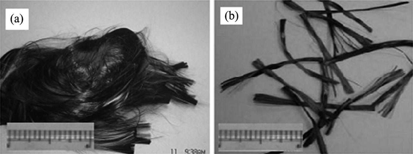
(a) Recovered CFs from CFRP and (b) waste (virgin) CFs. CF:carbon fibre; CFRP: carbon fibre-reinforced polymer; CF: carbon fibre.
Resin fibres
Commercially available PP staple (average 60 mm long and 3.3 dtex) fibres (melting temperature 164.5°C, melt flow index 40.2 g/10 min, crystallinity 50%) were sourced from Drake Extrusion, Bradford, UK. The PP fibres were used as thermoplastic resin fibre in the CF/PP hybrid composite yarns.
Experimental
Characterization of CFs
Single-fibre tensile tests were carried out for both types of fibres in accordance with BS ISO 11566 (1996) standard for 10 specimens tested at 25 mm gauge length. SEM was used to observe the 20 fibre surfaces and their geometries. The SEM micrographs obtained (Figure 2) were used to determine the diameter of the fibres.
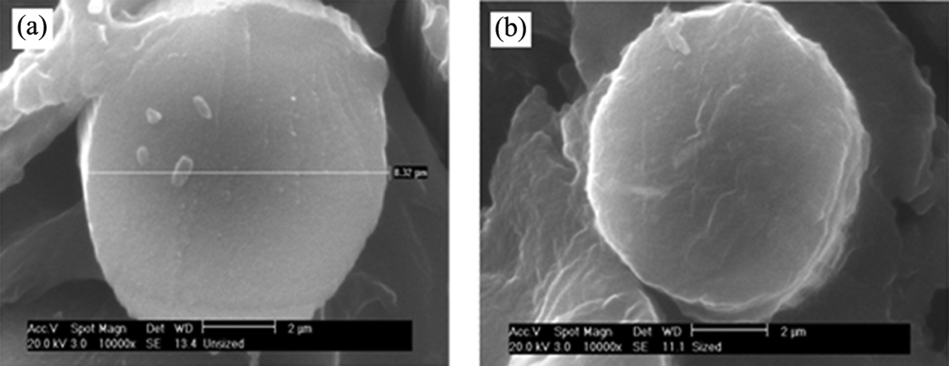
Diameter measurement of (a) rCF and (b) wCF using SEM. rCF: recycled carbon fibre; wCF: waste carbon fibre; SEM: scanning electron microscopy.
Composite fabrication
Spun yarns (yarn-reinforced CFs (YrCFs) and yarn waste CFs (YwCFs)) were produced from the blends of rCFs and wCFs with PP resin fibres using 50:50 weight ratios, respectively, by a modified carding and spinning processes. 5 The blends of CF/PP staple fibres were produced using a carding process to obtain a continuous sliver (weight; 7 ± 0.5 g m−1), which was subsequently drafted to convert into a wrap spun yarn of 1100 ± 100 tex 5 by hollow spindle spinning process. The intermingling of the staple rCFs and wCFs with the matrix fibres was achieved during the carding process and found that the crimped PP resin fibres acted as carriers for the uncrimped staple CFs. This provided the required fibre–fibre cohesion that helped individual separation of the CFs (termed opening) with minimum fibre breakage and good blending. The degree of intermingling of the fibres was assessed by an image analysis technique using the software Image Pro Plus (Media Cybernetics, Inc.). 5 Both the yarns produced were wound onto a steel frame unidirectionally (Figure 3(a)), and the layers were subsequently compressed and consolidated using hot compression moulding plates at 220 C under 20 bar pressure for 15 min (Figure 3(b)). Two types of composite plaques: C1 and C2 were fabricated using the rCFs/PP and wCFs/PP yarns, respectively, and the average nominal thickness of both the laminates was measured to be 1.4 mm.
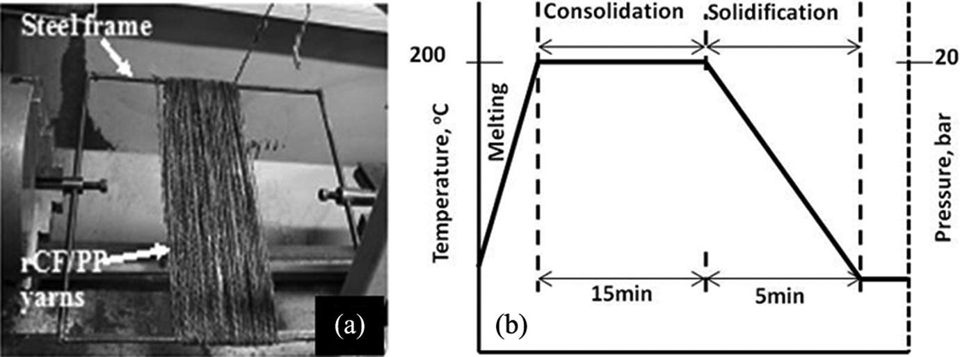
(a) rCF/PP yarns and yarn winding arrangement and (b) process cycle for composite moulding. rCF: recycled carbon fibre; PP: polypropylene.
Fibre volume fraction, CF orientation and mechanical testing of composites
Specimens from each plaque were used to determine CF mass fraction by pyrolysis in accordance with ASTM D2548-68. 23 The fibre volume percentages were determined from the mass fraction of CF. The mean fibre lengths and length distributions were measured by the Baer diagram/fibrogram technique 24,25 for 200 sample fibres from the specimens. To determine fibre orientation, optical microscopic observations (reflective mode) were made of polished cross sections taken at right angles to the axes of the sliver and yarn samples encapsulated in epoxy resin, and of the respective composite samples. The CFs that met the cross-sectional plane have either a circular or elliptical footprint; the former if aligned with the considered axis, the latter if inclined to the axis. The orientation of each fibre to the considered axis was, therefore, calculated from its ellipticity. 26,27 Tensile and flexural properties of the composite specimens were measured according to BS EN ISO 527-1:1996 and ISO 14125 standards, respectively.
Measurement of electrical conductivity of the composites
A four-probe technique was used to determine the conductivity and resistivity of the composite specimens (1.4 mm thick and 14.6 mm width) taken from each plaque, as depicted in Figure 4(a). Current was applied via probes 1 and 2, and the associated voltage was measured at probes 3 and 4. In order to obtain an adequate measure of the resistance of each sample, three probe separations (divided by probes 3 and 4) were used and the resistivity (ρ) was then obtained via equation (1). (a) Four-probe set-up during intrinsic resistance measurement, (b) arrangement for temperature measurement in different lengths and (c) brass block to reduce contact resistance of the composite specimen.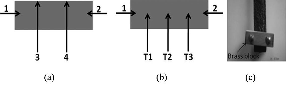
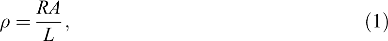
where, R is the measured resistance, A = 20.4 mm2 is the cross-sectional area of the specimen and L is the measurement length of the voltage drop (i.e. probe separation, Table 1).
Resistance of the C1 composite in different probe lengths and average values for both C1 and C2 composites.
In all cases, the current was ramped from −5 to 5 mA in 0.01 mA steps, and the voltage was simultaneously measured using a Keighley 2400 source meter and two Keithley (Berkshire, UK) 6514 system electrometers.
Temperature measurement
Temperature of the composite specimen increases as current passes through it depending on the resistance of the material. K-type thermocouples were attached to the specimens to measure the temperature rise with the increasing current. Different voltages were applied to the end of the each specimen via probes 1 and 2 as shown in Figure 4(b), and the associated temperature rise was recorded on a thermocouple data logger (TC-08; Pico Technology, Cambridgeshire, UK). To reduce contact resistance to a minimum, contact was achieved using brass blocks clamping the two ends of each sample (Figure 4(c)). The temperature was monitored at three different positions (0.25, 0.5 and 0.75 mm of the total length of the tested sample) along the sample as shown in Figure 4(b).
Results and discussion
Mechanical properties of composites
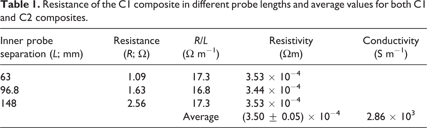
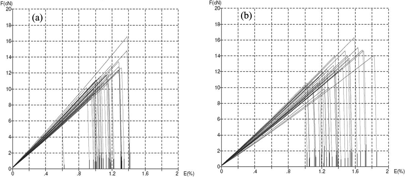
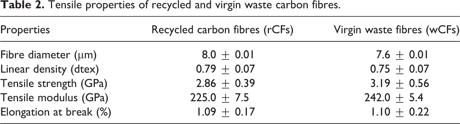
The load-extension curves obtained from the tensile testing of 20 single filaments of rCFs and wCFs (Figure 5(a) and (b)) and the summary of the test results were listed in Table 2. The results showed that the rCFs had up to 90% of the virgin fibre strength (rCFs = 2.86 GPa and wCFs = 3.19 GPa) and approximately 7% lower in modulus (rCFs = 225 GPa and wCFs = 242 GPa). The change in other properties such as fibre diameter and breaking extension was found to be insignificant for rCFs compared with wCFs (Table 2). As a result of recovery process at 500°C, the rCFs become more brittle and then broke more readily during the yarn production process due to unsized surface (size was removed during the recovery process). 5 Therefore, composite yarns produced from rCFs/PP blends by carding and the hollow spindle wrap spinning method contained 20 ± 1 mm long rCFs (Figure 6(a)). On the other hand, less CFs breakage occurred during wCFs carding and spinning process, which was due to epoxy-based sizing materials on the fibre surface protecting the fibres from surface abrasion during carding process. 5 Therefore, the average CFs length in YwCFs was found to be 40 mm ± 5 (Figure 6(b)).
Load-extension curves of (a) recycled and (b) virgin waste carbon fibres.
Length distribution of CFs in (a) YrCF and (b)YwCF yarn samples. CF: carbon fibre; YrCF: yarn-recycled carbon fibre; YwCF: yarn waste carbon fibre.
Tensile properties of recycled and virgin waste carbon fibres.
It is found that the composite sample C1 fabricated from the YrCFs contained 40% rCFs by weight (25.5% by volume) and C2 composite made of YwCFs contained 46% wCFs by weight (30.5% by volume), respectively. The reduction in CFs content may be attributed to the loss of the very short lengths of broken fibres that occurred during the carding process. Figure 7(a) shows that composite C1 exhibits tensile and flexural strengths of 115 MPa and 125 MPa, respectively, whereas the composite C2 have approximately 40% higher values (tensile strength of 160 MPa and flexural strength of 154 MPa). The tensile and flexural moduli were found to be 32 and 27 GPa for C2 composites, respectively. For C1 composites, the values were found to be 21 and 17 GPa, respectively (Figure 7(b)). The tensile modulus was increased by 52%, and flexural modulus was increased 42% higher for C2 composites compared with C1 composite. Better mechanical properties were obtained for the wCFs-reinforced composite C2 due to the longer CFs used and the higher fibre volume fraction found in the composite. It was also found from the CFs orientation measurement that the wCFs (composite C2) were better than that of rCFs (composite C1) as 90% of wCFs (C2) were found to be aligned at 10° from the machine direction, whereas the same percentage count of rCFs (C1) were aligned at 20° from the machine direction (Figure 8(a) and (b)). This better alignment of CFs in C2 composites compared to C1, was due to the less fibre breakage during commingling process (carding) of sized CFs with resin fibres compared with unsized rCFs, which resulted in longer fibre length (Figure 6).
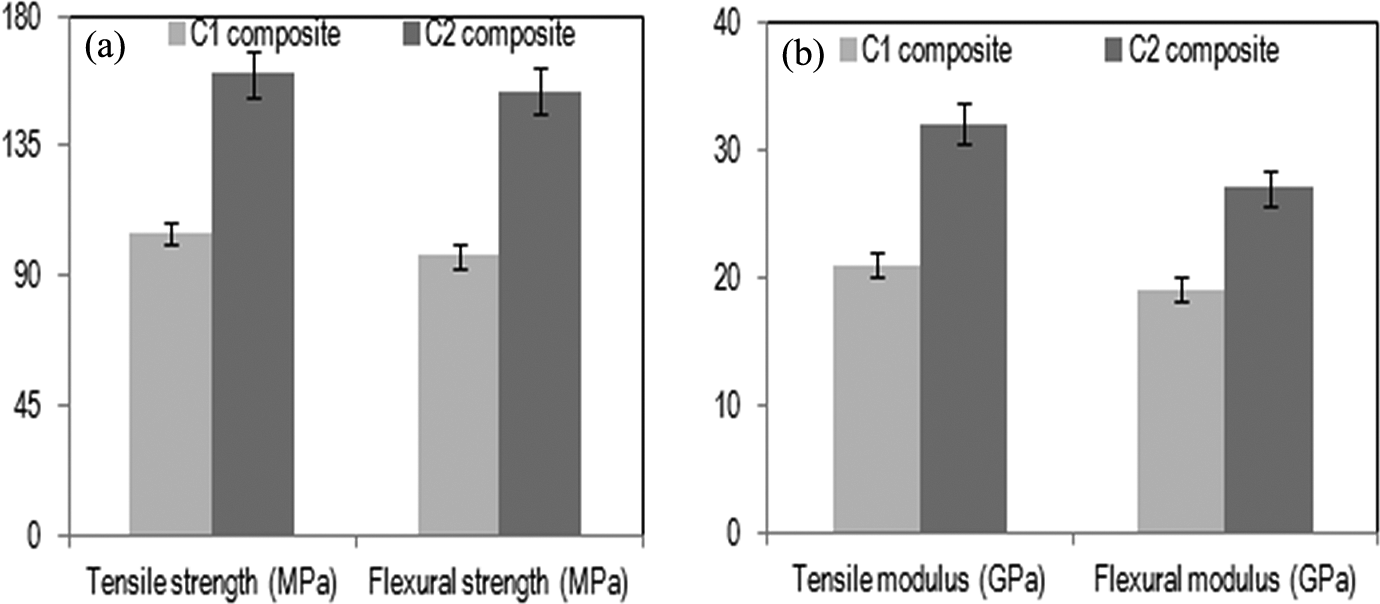
Tensile and flexural properties of the composites C1 and C2; (a) stengths and (b) moduli.
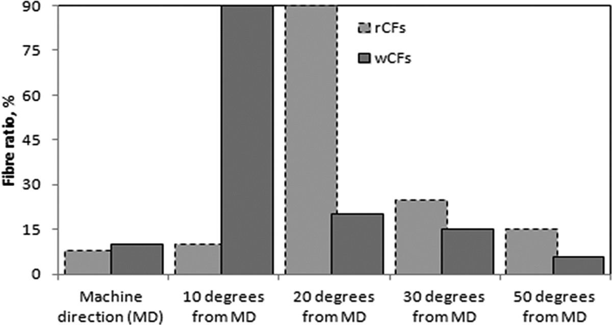
Fibre orientation in (a) C1 and (b) C2 composites.
Electrical properties of composites
By measuring the electrical properties, the results showed that the resistance of C1 varied along the specimen length controlled by the separations between the inner probes but the resistivity was quite consistent (Table 1). The average resistivity of 25.5% CFs volume fraction in composite C1 was 3.50 ± 0.05 × 10⁻⁴ Ωm and that of 30.5% CFs volume fraction in composite C2 was 0.93 ± 0.05 × 10⁻⁴ Ωm (Table 3) were in good agreement compared with the resistivity of pure carbon (0.35 × 10⁻⁴ Ωm). 28,29 By comparing the summary of the electrical results (Table 3), it is found that the sample C1 with 20 mm CF long had a conductivity of 2.86 × 10³ S m−1 and the C2 sample of 40 mm CF long had a conductivity of 10.75 × 10³ S m−1. The lower resistivity or the better conductivity of composite C2 can be referred to the high CF%, longer and more aligned CFs in the composite compared with lower volume fraction, shorter and less oriented CFs in C1 composite. The reason behind the higher conductivity of C2 composites was also assumed that longer and more aligned CFs tend to create higher contact points than shorter and less aligned CFs, and hence, increasing the amount of direct conduction path in C2 composite helped quicker pass of current through the material.
Resistivity and conductivity of the composites C1 and C2.
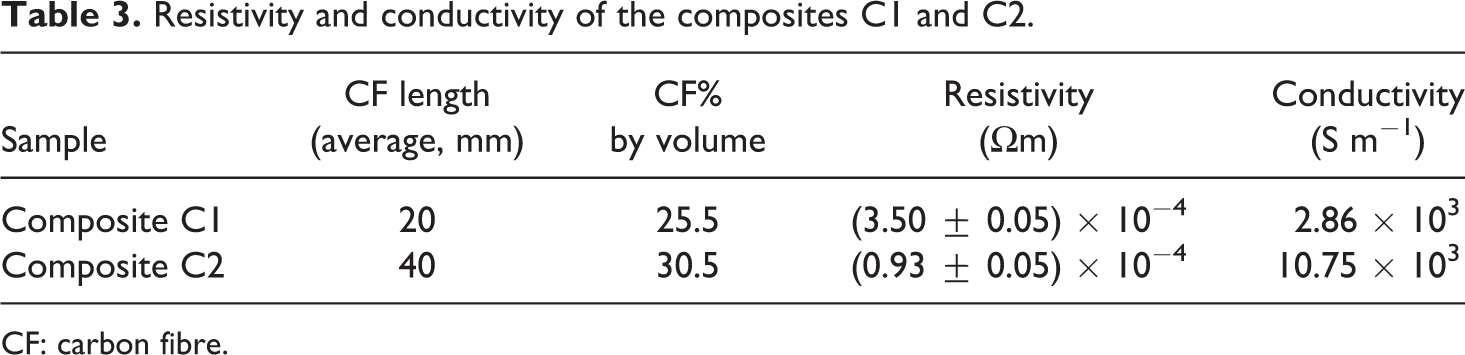
CF: carbon fibre.
The temperature values were measured for an applied voltage of 5 V and a current of 0.9 A to the ends of the C1 specimen via probes 1 and 2. The temperature of the samples was monitored at three positions along the length. The contact resistance at those positions controlled the current that the sample can pass and hence the temperature rises along the sample. It was found that in three zones of the both specimens showed that the path of the temperature rising to reach the final stages were fairly consistent along the sample length (Figure 9), which meant that CFs in the composite specimens are well distributed. The final temperature values were also reasonably consistent along the sample length; however, the slight variations were probably due to the morphology of the sample. The morphological variation may be occurred due to local CF network structure that depends on CF length and distribution in the specimen. The key feature of these results is that the temperature remains low for certain amount of time (Figure 10), until the current suddenly increases (resistance decreases as the voltage is fixed) and hence the temperature dramatically rises.
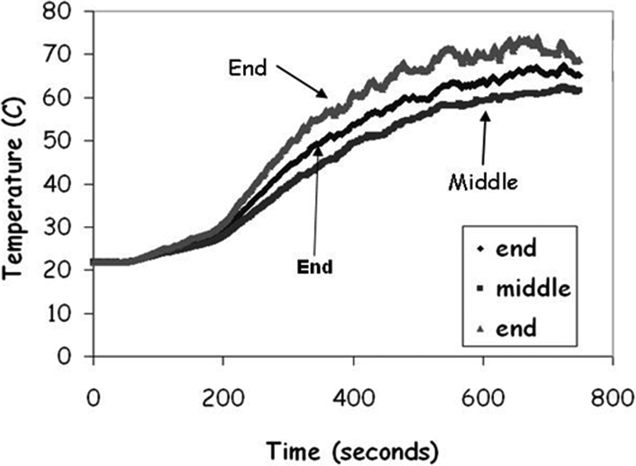
Temperature measurement in three different zones of C1 specimen.
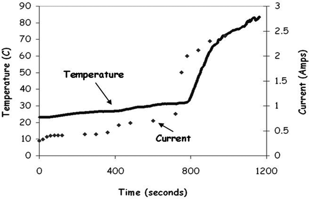
Simultaneous temperature and current measurements for the C1 composite.
By examining the contact points 1 and 2 after the test suggested, it is noticed that local heating occurs at these contacts. This is due to the local temperature rise until the polymer softens. As the polymer start to soften, the contact with the CF network is improved, the contact resistance reduces and so the current increases. If the sample is allowed to cool and then tested again, without removing the contacts, then the temperature rises immediately as the contact resistance has already been lowered (Figure 11). The results showed that if the contact resistance is high, then the inception time to ‘break down’ the contact resistance could vary significantly and would be unpredictable. It is also seen that if good contact could be made in the first instance (i.e. the contact resistance is low), then the temperature rise could reach a maximum in around 5 min, which was achieved in experiment using brass blocks method for C1 (Figure 12). As the brass blocks gave a much lower contact resistance, higher current was allowed to pass into the samples. The current for any applied particular voltage remained constant through each experiment, confirming that the brass blocks were providing both a low contact resistance and a consistent one.
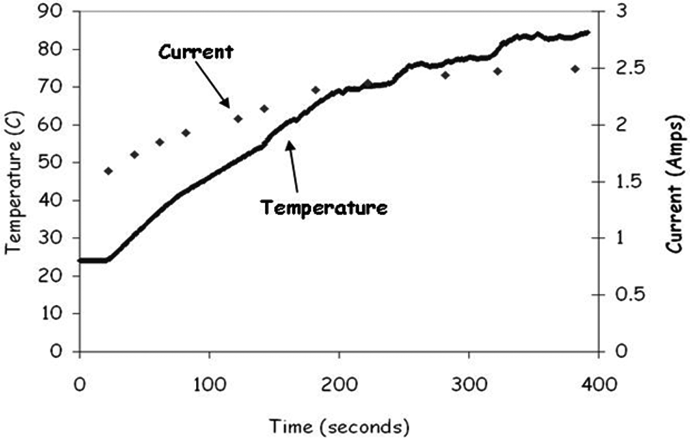
Simultaneous temperature and current measurement for the pretested specimen without removing the contacts after first test.
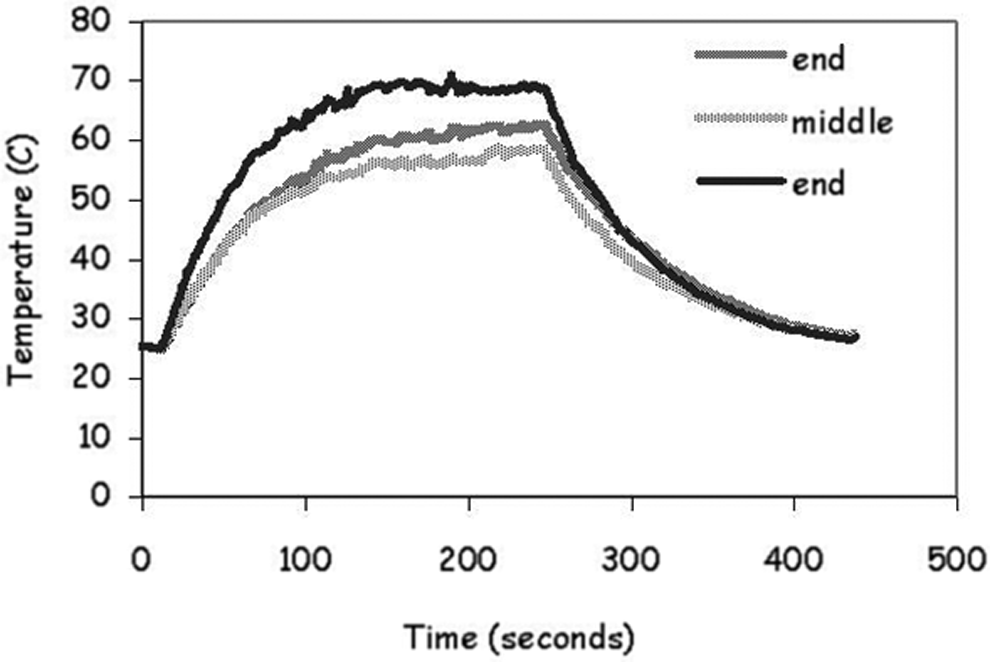
Temperature measurement in three different zones of C1 specimen using brass block as a low contact resistance.
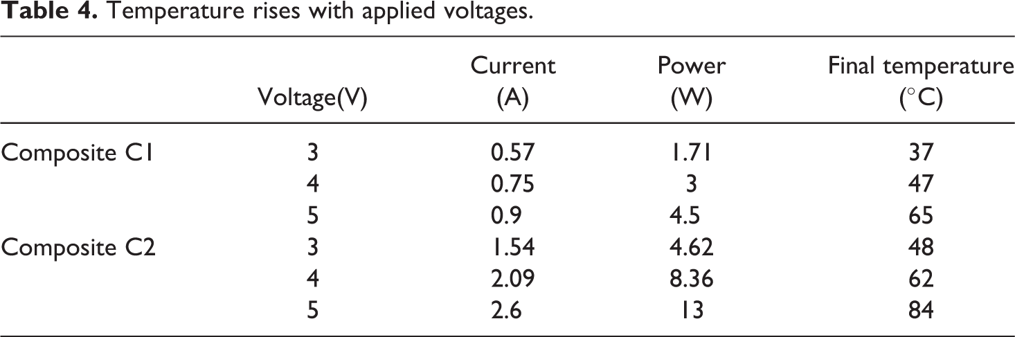
Table 4 gives values for the average peak sample temperature for different applied voltages (and hence applied power). As the sample heats up, the resistance falls and so the current increases, causing a further temperature rise. The peak temperature occurs when these two processes reach a balance. The results show that as the applied voltage increased, the maximum temperature applied also increased. It was seen that the sample with the highest volume fraction of CFs (C2) had 3 times higher current flow compared with C1 when 3 Vwas applied and reached a plateau temperature of 48°C (37°C for C1) with the same applied voltage (Table 4). Similar effects were also found while applying other voltages (4 and 5 V; Table 4). The plateau temperature recorded was 84°C for C2 and 65°C for C1, when 5 V was applied (Table 4). Because of the longer, more aligned and higher percentage CFs, C2 had higher rate of heating with the same applied voltage compared with C1; however, both composite samples were seen to withstand those temperatures without showing the softening of the PP matrix during the experiment.
Temperature rises with applied voltages.
Conclusion
PP thermoplastic composite structures that contained 25.5% rCFs and 30.5% wCFs by volume showed reasonable mechanical properties and electrical conductivity. It was observed that the temperature rising through the material was significantly constant along the sample length, and this could be advantageous for low temperature heating applications. It was concluded that the composite C2 of longer and more aligned CFs exhibited better mechanical and electrical properties than the composite C1 of shorter CFs.
Footnotes
Declaration of Conflicting Interests
The author(s) declared no potential conflicts of interest with respect to the research, authorship, and/or publication of this article.
Funding
The author(s) disclosed receipt of the following financial support for the research, authorship, and/or publication of this article: The work presented in this article was carried out under Fibre Cycle project, which was co-funded by Technology Strategy Board’s Collaborative Research and Development Programme (Fibre Cycle; grant number GR/R80605/01) and industrial partners: Tilsatec Ltd.; Advanced Composites Group Ltd. (UK); NetComposites; Exel Composites (UK) and Sigmatex (UK).
Acknowledgement
Authors thank Dr Peter Hine, School of Physics and Astronomy, University of Leeds, UK, for his support in carrying out the project.