
Abstract
This study investigates a novel post-processing technique aimed at enhancing the mechanical properties of 3D-printed polypropylene-carbon fiber (PP-CF) composite parts. The method involves printing components with internal voids to reduce weight and printing time, subsequently filling these voids with a low-cost resin known for its superior mechanical properties. Through systematic experimentation varying infill density and pattern, key quantitative findings were obtained. Tensile strength generally increased with higher infill density, reaching a maximum of 55.664 MPa for the resin-filled triangle infill pattern with 60% infill density. Impact energy showed a decreasing trend with increasing infill density, with the highest impact energy of 0.5 J recorded for the resin-filled triangle infill pattern with 60% infill density. Microstructural analysis revealed that the triangle infill pattern at 60% infill density exhibited the most effective resin penetration, contributing to superior mechanical performance. These findings emphasize the importance of infill pattern selection in resin distribution and mechanical enhancement in 3D-printed composite materials.
Keywords
Introduction
In recent years, the advent of 3D printing technologies, specifically Fused Deposition Modeling (FDM), has revolutionized manufacturing processes, offering cost-effective and versatile solutions for producing complex geometries. FDM involves the layer-by-layer deposition of thermoplastic materials to build three-dimensional objects.1,2 Despite its numerous advantages, such as customization and rapid prototyping, FDM-printed parts often exhibit anisotropic mechanical properties and susceptibility to delamination. To address these challenges, various post-processing techniques have been explored. Some of the most effective post-processing techniques for FDM-printed parts include sanding, gluing, welding, vapor smoothing, polishing, priming painting, electroplating, and resin filling.3,4
One notable post-processing method is resin filling, which involves infusing the internal voids or infill structures of a 3D-printed part with a resin material. Infill, in the context of 3D printing, refers to the lattice-like or honeycomb structure inside a printed object that provides structural support. This internal structure can be modified by adjusting its density during the printing process. This innovation contributes to the overall effectiveness of resin filling as a post-processing technique in augmenting the mechanical properties of 3D-printed parts. Saraf and Barodiya 5 reviewed the diverse post-processing techniques for FDM 3D printed parts, including resin filling. The authors present an extensive overview of the resin filling process, discussing its advantages and limitations, and highlighting its applications in various fields. Hussam et al. 6 enhanced mechanical properties in FDM-printed ABS specimens. They achieve an impressive 86% tensile strength compared to injection molding and introduce a post-filling technique, resulting in a 151% improvement in strength-to-weight ratio and a 51% cost reduction. Belter and Dollar 7 investigated the enhancement of 3D-printed part strength and stiffness by strategically introducing voids in the printed components and subsequently filling them with high-strength resins. Their findings indicate a substantial improvement, with overall part strength increased by up to 45% and stiffness by up to 25%.
Resin filling of infill structures in 3D-printed parts is a strategic post-processing technique that synergistically combines the advantages of 3D printing with the enhanced mechanical properties of resin materials. This method proves valuable in applications demanding improved strength, energy absorption, and overall performance of printed components. The choice of infill density significantly influences the mechanical properties of the printed parts, impacting factors such as strength, stiffness, and weight.6–8 While prior studies have investigated the effects of infill on the overall mechanical performance of FDM-printed parts, there remains a gap in understanding the influence of infill in conjunction with additional materials, such as epoxy resin, on the mechanical behavior.
PP (Polypropylene) was chosen for its versatile properties, including excellent strength, stiffness, and chemical resistance, making it suitable for various applications. Its semi-crystalline nature allows for precise control over crystallinity, influencing mechanical properties. Additionally, PP is cost-effective and exhibits good compatibility with 3D printing processes, ensuring smooth extrusion and high-quality prints. Compared to other commonly used materials like PLA and ABS, PP offers a compelling balance of mechanical performance, ease of printing, and cost-effectiveness, making it an ideal choice for enhancing the mechanical properties of 3D-printed parts. 9
In the realm of post-processing techniques for 3D-printed parts, this study introduces a novel approach by employing Carbon Fiber (CF) reinforced Polypropylene (PP) filament instead of the commonly used ABS and PLA materials. 10 Polypropylene (PP) stands out as a highly versatile semi-crystalline polymer, offering adaptability to fulfill specific processing and application needs with an optimal balance of processability, strength, stiffness, and chemical resistance, all at a cost-effective level. This departure from traditional thermoplastics stems from the unique advantages offered by CF-reinforced PP, which include enhanced mechanical strength, durability, and chemical resistance. Unlike the conventional choices of ABS and PLA, CF-reinforced PP provides a superior combination of properties suitable for applications requiring robust mechanical performance. The incorporation of CF reinforcement contributes to increased tensile strength, impact resistance, and overall part durability, making it an innovative choice for 3D printing applications. This novel material selection aligns with the growing demand for high-performance materials in additive manufacturing, showcasing the potential for CF-reinforced PP filament to elevate the mechanical properties of 3D-printed components beyond the capabilities of more commonly used thermoplastics. Therefore, PP-CF material has been chosen for this study, and its usage in the literature is notably limited.8,11
In this study, the post-processing technique is implemented with the objective of enhancing mechanical properties while concurrently reducing costs and weight. The novelty of the paper lies in its innovative approach, which combines the utilization of Carbon Fiber reinforced Polypropylene (PP-CF) filament and epoxy resin post-processing techniques to significantly enhance the mechanical properties of 3D-printed parts while reducing costs and weight. The methodology involves printing components with internal voids, resulting in decreased part weight, reduced printing time, and subsequently lowering overall printing costs. Subsequently, these voids are filled with a low-cost, less dense resin known for its superior mechanical properties. To achieve internal sparsity, voids are designed and positioned through slicing software, which manages this process by adjusting the infill density and infill pattern parameters. In this particular investigation, slicing software is utilized to create sparse parts with three different infill densities (20%, 40%, and 60%) and three different infill patterns (Grid, Triangle, Trihexagon). These parts are then injected with epoxy resin, a material that is more cost-effective than PP-CF. The infill pattern facilitates optimal resin distribution throughout the entire part. Tensile tests, impact tests, and morphology analyses are conducted to evaluate the efficacy and improvements introduced by this technique.
Materials and Methods
Printing of Test Specimens
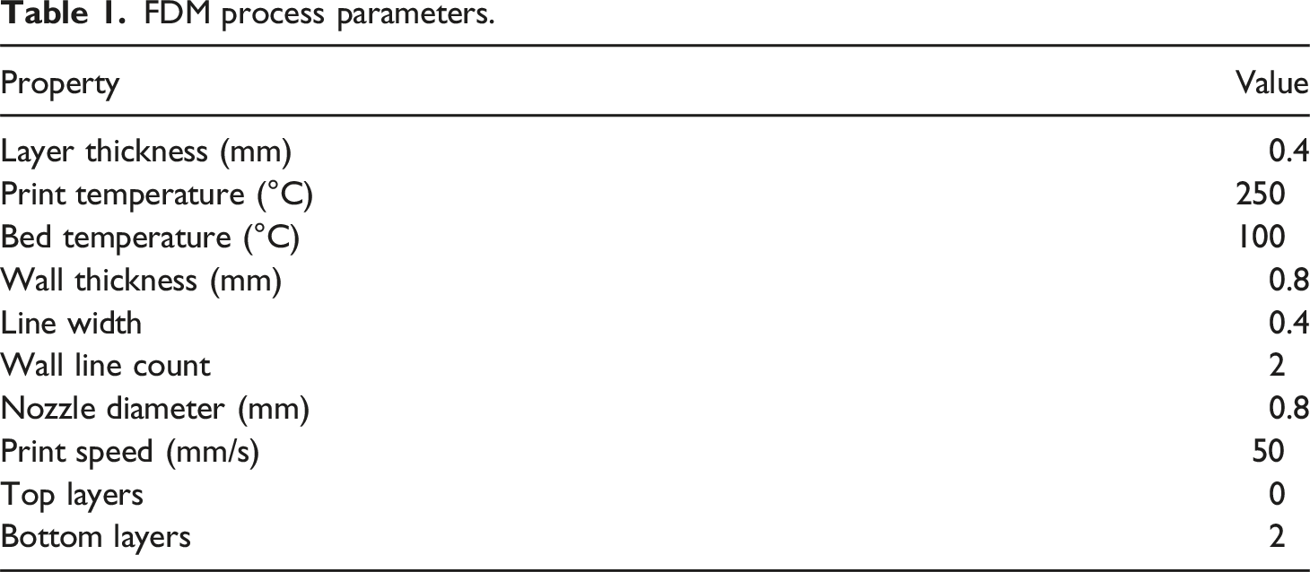
FDM process parameters.
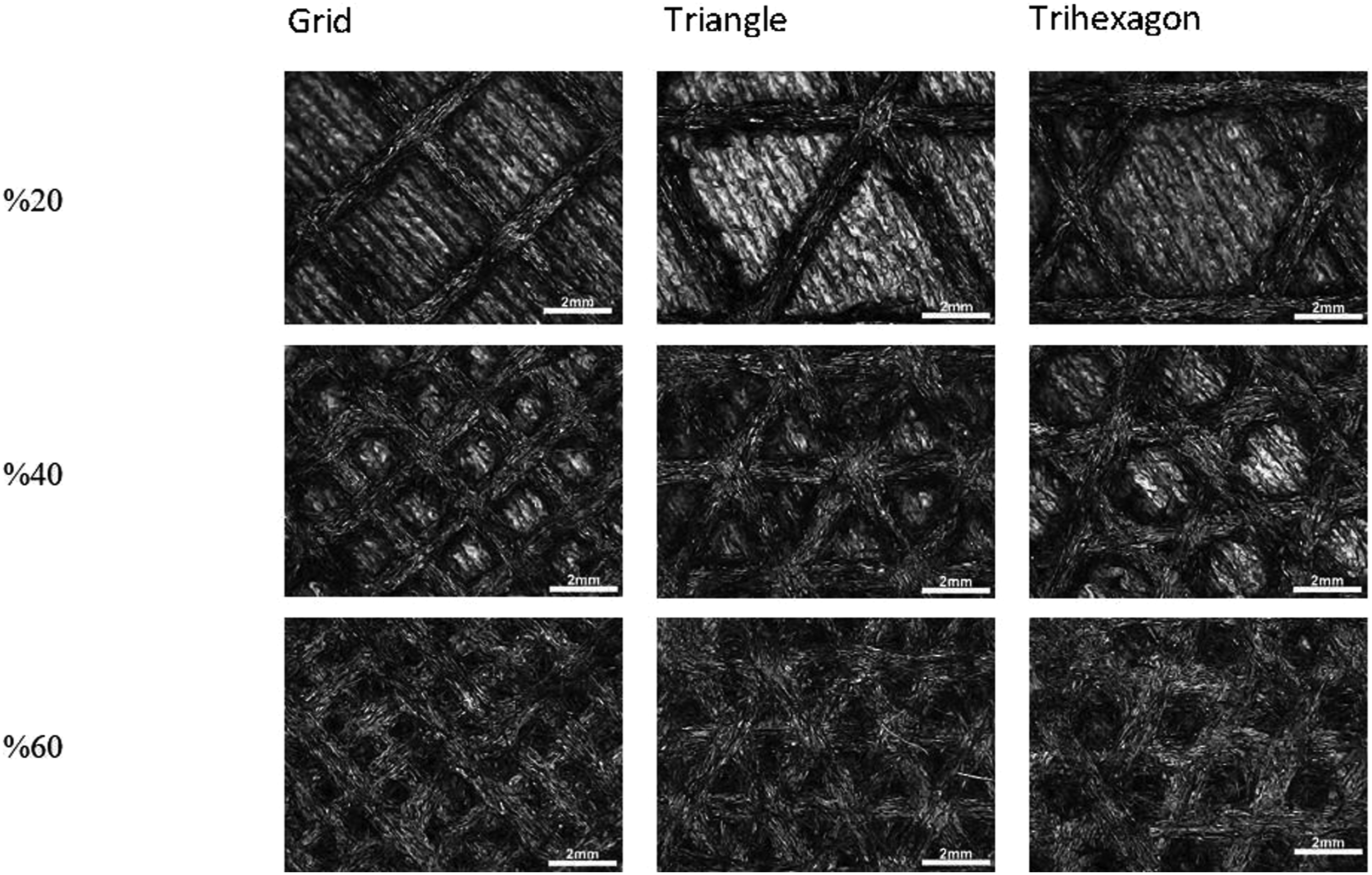
The optical microscope images of the infill densities and infill patterns of samples.
Post-processing with Epoxy Resin
Subsequent to 3D printing, the test specimens underwent post-processing with EPAKEM epoxy resin. The resin, consisting of A and B components (base and hardener), was mechanically mixed for 2 min. To eliminate air bubbles within the resin, the mixture was placed on a heated bed at 40°C for 6 min.
After degassing, the epoxy resin was injected into the infill voids of the 3D printed PP-CF samples using a syringe. In this technique, tensile and impact test specimens were 3D printed with internal voids intended to be filled with epoxy resin. The PP-CF parts were designed to have internal sparsity using slicing software, which regulates the part density through the infill percentage parameter. Three different infill percentages (20%, 40%, and 60%) were printed, each with distinct patterns facilitating resin flow throughout the entire specimen. The bottom layer was sealed, while the top layers remained open. Resin was injected through the open top surface, resembling a casting process into the pattern voids (Figure 2). This process aimed to enhance the mechanical properties of the specimens by reinforcing the internal structure. PP-CF 3D printed samples with 20% infill density, Triangle pattern: (a) 3D printed samples, (b) Resin filling of infill structures in 3D-printed parts.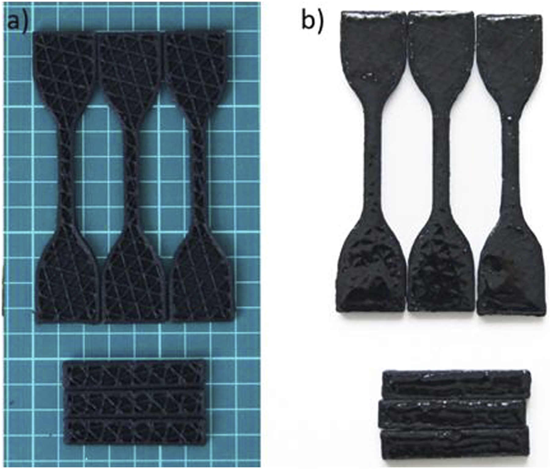
Experimental Design
Tensile tests were performed using a Shimadzu Autograph (50 kN) machine, with a testing speed of 5 mm/min at room temperature. The dog bone-shaped tensile test samples were prepared in accordance with ASTM D412 Type C specifications. The ASTM D412 Type C specimen dimensions included an overall length of 115 mm, an overall width of 25 mm, a gauge length of 25 mm, a narrow length of 33 mm, a grip length of 65 mm, a gauge width of 6 mm, a thickness of 4 mm, a radius of fillet at 14 mm, and an outer radius of 25 mm. Izod impact strength measurement was performed using a pendulum impact tester (Zwick) with a pendulum energy capacity of 6 J, following ISO 180 standards. Standard multipurpose samples of 45° V-notched Type 1A, measuring 10 × 4 × 80 mm, were used for this purpose, with a notch depth of 8 mm beneath the sample. The analysis of the fractured surfaces of PP-CF parts was carried out using scanning electron microscopy (SEM) on a Zeiss EVO MA10 device at a 10 kV acceleration voltage. Before the experiment, all samples were uniformly sized and received a gold coating on the surface. CT scan images were acquired using a GE High Speed Advantage CT Scanner, utilizing parameters of 80 kVp, 280 mAs, with a slice spacing and thickness of 1 mm each. Contact angle measurements were conducted to analyze the wetting behavior and surface adhesion of the epoxy resin on the polypropylene-carbon fiber (PP-CF) composite samples. Contact angle measurement is a crucial technique for assessing the degree of wetting of a liquid on a solid surface. Contact angle tests were conducted by depositing resin droplets, resin + hardener droplets, and water droplets onto PP-CF samples using an OCA 15EC DataPhysics instrument. Images were captured 5 s after deposition to analyze the wetting behavior and surface adhesion of the resin.
Results and Discussion
Tensile Testing
Weight of the Resin-free and resin-filled 3D printed samples.
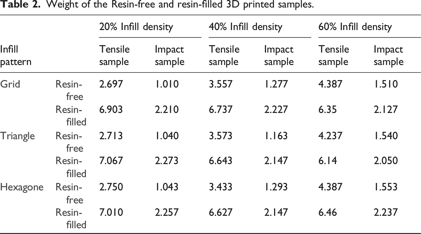
The impact of epoxy resin filling within PP-CF printed parts is illustrated in Figure 4. The variables considered were the infill density during printing and the infill pattern of the parts, consequently affecting the injected volume of epoxy. According to Figure 4 and Table 3, tensile strength generally increases with higher infill density, regardless of pattern. As expected, increased infill density and resin filling lead to heavier samples. This is because more material is present in the structure. Higher infill density implies more material present within the structure, leading to a larger cross-sectional area resisting applied forces. This inherently translates to improved load-bearing capacity and, consequently, higher tensile strength.11,12 The tensile strength of the resin-filled 3D-printed PP-CF specimens exhibited notable variations based on the infill pattern and density. The resin-filled triangle infill pattern with 60% infill density achieved the highest tensile strength, reaching 55.664 MPa due to its combination of increased material concentration, potentially favorable stress distribution, and the reinforcement provided by the resin. In contrast, the resin-filled grid infill pattern with 40% infill density demonstrated the lowest tensile strength at 41.211 MPa. The resin-filled triangle infill pattern with 60% infill density achieved the highest tensile strength but also resulted in the heaviest samples (7.067 g for resin-filled tensile samples) (Table 2). Increased material concentration generally contributes to higher strength.
13
Chadha et al.
14
reported comparable findings in their investigation of the performance of grid, triangular, and honeycomb infill patterns under both flexural and tensile loads. Stress-Strain diagram of the samples. Mechanical properties of the resin-filled 3D printed samples.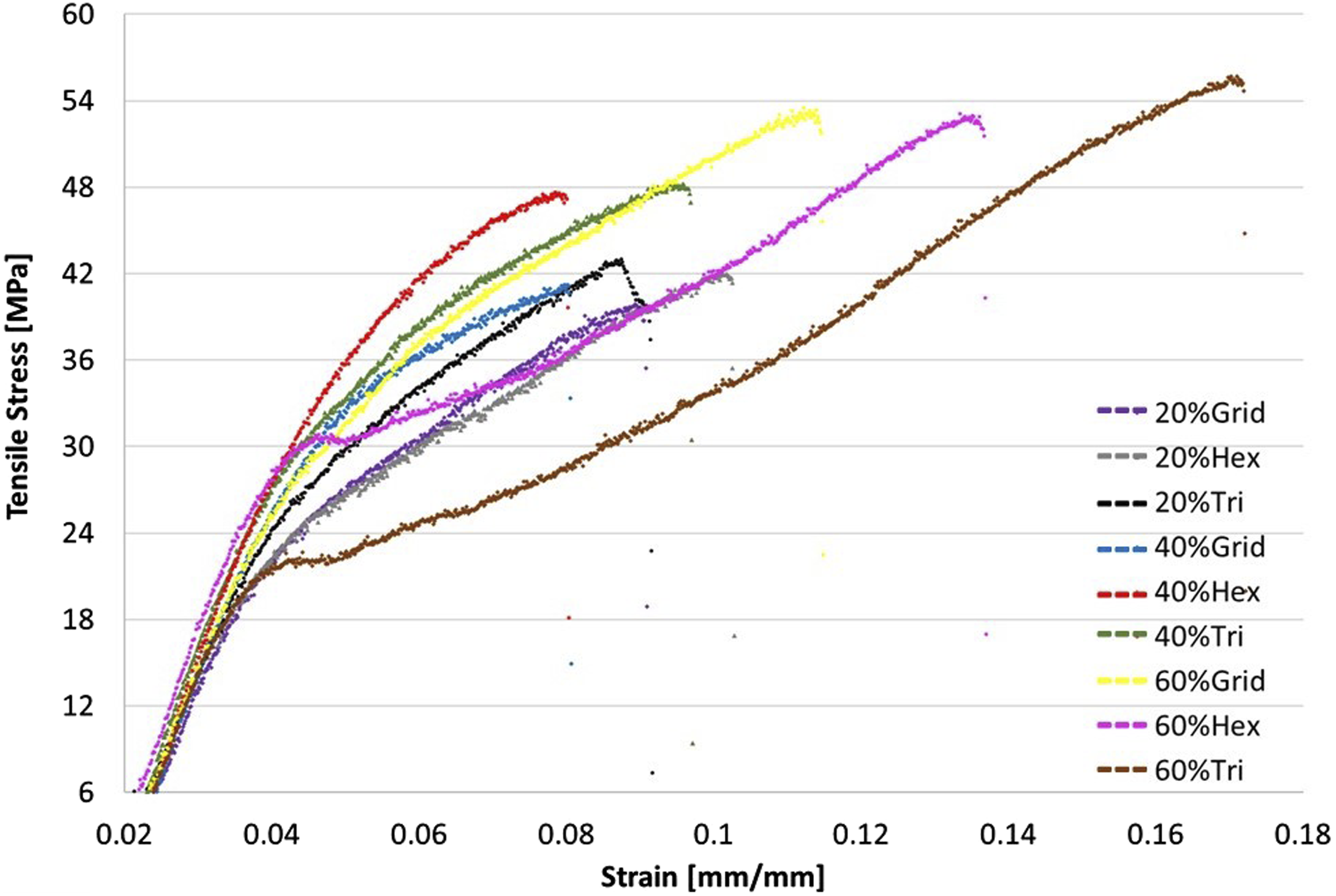
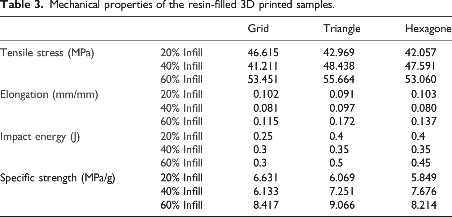
The resin-filled triangle infill pattern with 60% infill density exhibited the highest elongation of 0.172 mm/mm, suggesting increased flexibility and deformation capability (Table 3). This result suggests that the resin-filled triangle pattern, with its specific geometry, may create zones of flexibility, allowing for localized stretching before reaching the breaking point. However, flexibility in other patterns, such as grid or honeycomb, was dependent on their orientation and density which is in agreement with.15,16 While higher density generally increases stiffness and decreases elongation, the optimal density for maximizing elongation can vary depending on the pattern and material. In some cases, a moderate density like 60% might allow for enough material to resist deformation while still retaining some flexibility.
The tensile strength of resin-free samples with a 60% infill density was initially measured at 20.51 MPa. However, with the implementation of resin filling post-processing techniques, a substantial enhancement in mechanical performance was observed. The maximum tensile strength recorded after the resin filling process exhibited a significant increase of approximately 171.7%. This noteworthy enhancement underscores the effectiveness of the resin filling technique in reinforcing the material and improving its tensile strength.
Impact Testing
Analyzing impact energy (Table 3), a general decreasing trend was observed with increasing infill density. Karad et al. 17 reported that the energy absorption was maximum for all infill schemes at higher infill densities, according to the results of the Izod impact test trials on specimens. The highest impact energy of 0.5 J was recorded at the resin-filled triangle infill pattern with 60% infill density, while the resin-filled grid infill pattern with 20% infill density exhibited the lowest impact energy at 0.25 J. The difference in impact energy can be attributed to the specific geometric features and density variations among different infill patterns. The resin-filled triangle infill pattern with 60% infill density may provide a configuration that potentially enhanced energy absorption due to its geometry, allowing for localized stretching before failure. On the other hand, the resin-filled grid infill pattern with 20% infill density may have fewer opportunities for energy absorption, resulting in lower impact energy values. These variations highlight the influence of infill pattern geometry and density on the material’s response to impact forces.18,19
The specific strength of a material, expressed in megapascals per gram (MPa/g), provides a key insight into its ability to withstand applied forces relative to its weight. In our study, we observed variations in specific strength across different infill densities. For the 20% infill density samples, specific strength ranged from approximately 5.849 MPa/g to 6.631 MPa/g, while for the 40% infill density samples, it ranged from approximately 6.133 MPa/g to 7.676 MPa/g. The highest specific strength values were observed in the 60% infill density samples, ranging from approximately 8.214 MPa/g to 9.066 MPa/g. These findings underscore the importance of infill density in determining the specific strength of 3D-printed parts, with higher infill densities generally resulting in greater specific strength. Overall, materials with higher specific strength values exhibit superior mechanical performance per unit mass, making them particularly advantageous for weight-sensitive applications where maintaining strength while minimizing weight is paramount.
Microstructural Analysis
Figure 5 depicts scanning electron microscope (SEM) micrographs illustrating the fracture surfaces of polypropylene-carbon fiber (PP-CF) parts filled with resin. SEM micrograph of resin-filled PP-CF specimens: triangle 20% (a), triangle 40% (b), triangle 60% (c), grid 20% (d), grid 40% (e), grid 60% (f), hexagone 20% (g), hexagone 40% (h), hexagone 60% (i).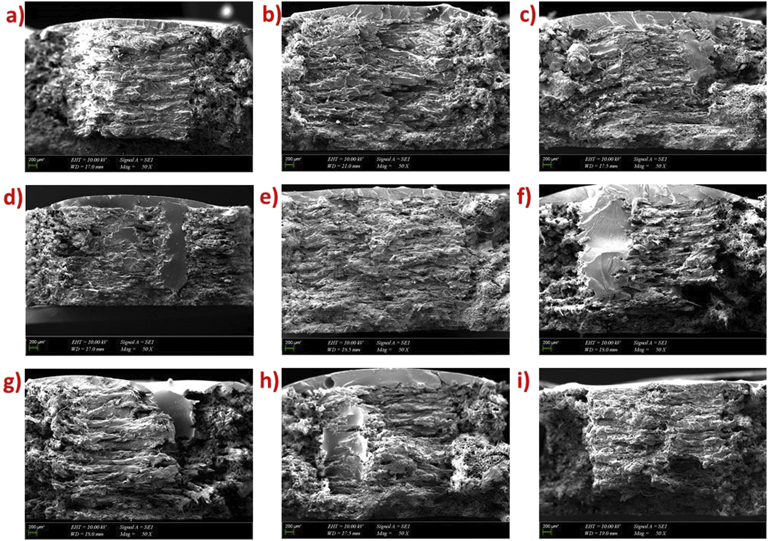
At lower infill densities, Figure 5(a), 5(d), 5(g) the resin has the ability to penetrate deeper into the infill structure during the manufacturing process. This enhanced permeability is likely due to the increased spacing between individual infill strands, allowing the resin to flow more freely and reach greater depths. As a result, the microstructure analysis reveals a more thorough impregnation of resin throughout the interior of the part. On the contrary, at higher infill densities (Figure 5(c), (f), (i)), the closely packed infill structure creates a barrier that restricts the infiltration of resin into the inner regions of the part. The reduced inter-strand spacing hinders the resin’s ability to penetrate effectively, resulting in a limited depth of resin impregnation. Microstructure analysis in these instances is expected to show a more surface-oriented resin distribution, with a discernible boundary between the outer layers and the interior. However, it’s noteworthy that the choice of infill pattern plays a crucial role in resin distribution. In particular, the triangle infill pattern was more successful in distributing the resin. This effectiveness can be attributed to the inherent characteristics of the triangular geometry, which facilitates optimal resin flow and penetration. Because triangular structures inherently have fewer connecting points than square (grid) or hexagonal patterns. This reduced connectivity can allow the resin to flow more easily through the larger spaces, aiding in deeper penetration. Also, the orientation of triangles can provide pathways for resin to move more freely in different directions, contributing to enhanced penetration.6,20,21
The resin-filled triangle infill pattern with a 60% infill density yielded the highest mechanical properties. This observation is supported by SEM images, where the effective penetration and distribution of resin within the printed structure can be clearly seen. The specific geometry and density of the triangle infill pattern at 60% contribute to optimal resin impregnation, resulting in enhanced structural integrity and superior mechanical performance. Parab and Zavari 22 showed that triangular infill was superior to the default line infill pattern in every condition. Cho et al. 23 displayed that the triangular infill pattern had the highest tensile strength and the lowest deformation rate. Godec et al. 24 observed that the triangular infill pattern had the highest compression strength compared to other infill patterns. Our findings align with existing literature.
Upon comparing Figure 6(a) and 6(b), in the resin-free sample, the presence of stratification was apparent, whereas in the resin-filled sample, the distinct layers became indiscernible. The reduction in porosity, as noticeable in Figure 3(b), resulted in enhanced mechanical properties. SEM micrograph of fracture surfaces of samples: (a) resin-free (b) resin-filled. The 3D-printed parts after the resin filling technique: (a) Grid infill pattern, (b) Triangle infill pattern, (c) Trihexagon infill pattern.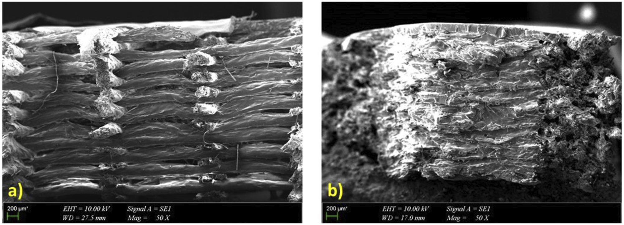
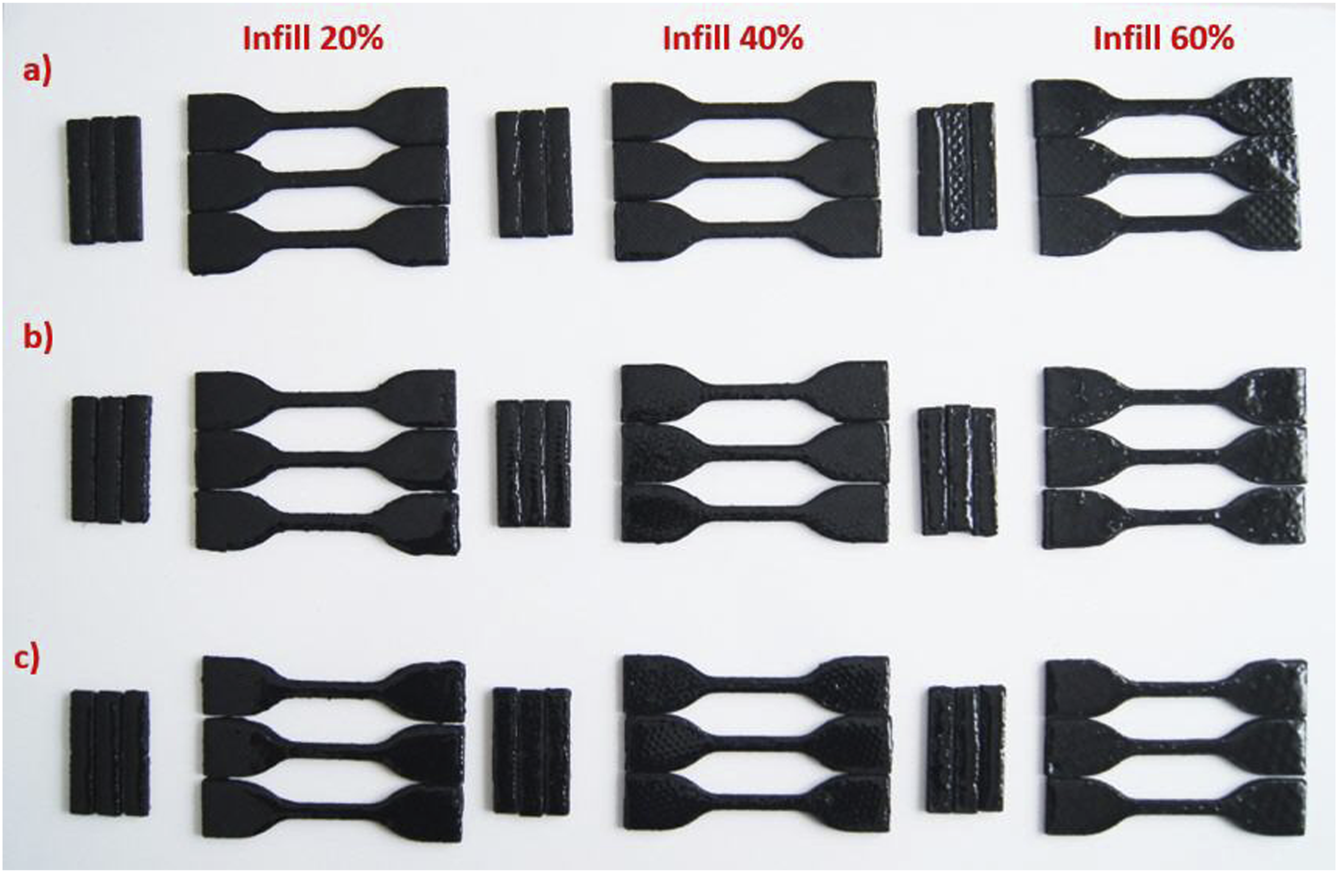
Figure 7 reveals the presence of short carbon fiber (CF) particles. The interfacial bond between the fibers and the matrix is not as perfect as assumed in the literature.
25
This imperfection in bonding explains why an elevated carbon fiber content does not exert a substantial influence on the strength of the composite, leading to the selection of a constant CF content (15% by weight.) for this study. SEM micrograph depicting the orientation of carbon fibers.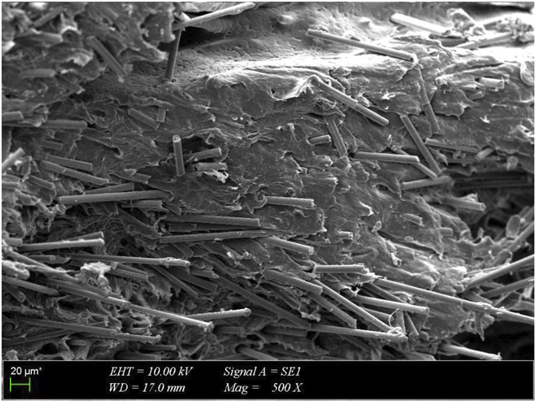
Contact angle measurements were conducted to analyze the wetting behavior and surface adhesion of the epoxy resin on the polypropylene-carbon fiber (PP-CF) composite samples, as shown in Figure 8. A contact angle greater than 90° indicates poor wetting, while a contact angle less than 90° suggests good wetting. The contact angle of the resin on the PP-CF surface was found to be 59.33°, while the contact angle of the resin + hardener on the PP-CF surface was found to be 55.18°. Additionally, the contact angle of water on the PP-CF surface was found to be 78.29°. Comparing these values, it can be observed that the contact angle of the epoxy resin on the PP-CF surface is less than 90°, indicating good wetting behavior. The contact angle measurement results provide evidence that the epoxy resin effectively wets the PP-CF surface. This suggests strong surface adhesion and indicates that positive pressure is not required for resin flow into the sample. The resin’s ability to wet the PP-CF surface is crucial for the success of the post-processing technique, as it ensures proper resin distribution within the printed parts, ultimately enhancing their mechanical properties. Therefore, based on the contact angle measurements, it can be concluded that the epoxy resin effectively wets the PP-CF surface, contributing to the mechanical enhancement of the 3D-printed composite parts. Contact angle measurements of CF-PP samples.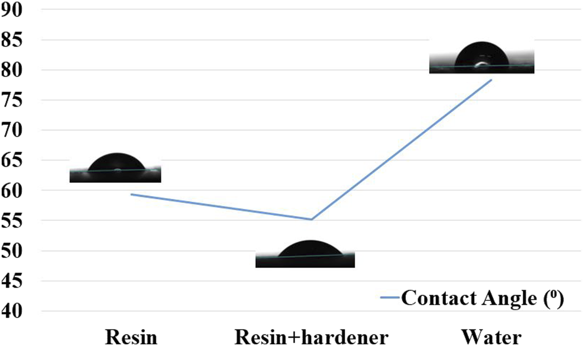
Based on the CT scan image (Figure 9), the 60% infill resin-filled sample exhibits a notable absence of air gaps, indicating successful and thorough filling by the resin material. The white areas observed in the image represent dense resin, evenly distributed throughout the sample volume. Conversely, the minimal presence of black areas suggests a lack of air pockets or voids within the resin filling, indicating successful resin infiltration without porosity within the infill structures. The 60% infill resin free sample displays a network of black, low-density areas, likely representing the infill material used in the 3D printing process. The white regions likely correspond to the empty spaces between the infill structures. The overall distribution of black and white areas suggests a regular or controlled pattern of the infill material, consistent with a 60% infill density. The CT scan images demonstrate a regular or controlled pattern of the infill material in both samples, with successful resin filling evident in the absence of porosity within the infill structure of the resin-filled sample. CT Scan of samples (a) 60% infill resin filled, (b) 60% infill resin free.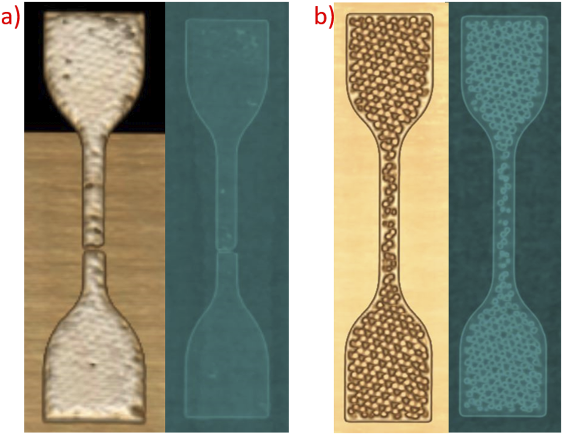
Conclusion
In this study, a novel post-processing technique was implemented to enhance the mechanical properties of 3D-printed polypropylene-carbon fiber (PP-CF) composite parts. The method involved printing components with internal voids to reduce weight and printing time, subsequently filling these voids with a low-cost, resin known for its superior mechanical properties. The influence of infill density and pattern on the mechanical properties was systematically investigated, revealing insights into tensile strength, elongation, and impact energy. The resin-filled triangle infill pattern with a 60% infill density emerged as the optimal configuration, achieving the highest tensile strength and notable elongation. Microstructure analysis provided further understanding of resin distribution in varying infill conditions, with the triangle infill pattern demonstrating superior resin penetration. These findings underscore the importance of infill pattern selection in resin distribution and mechanical performance. The study contributes valuable knowledge to the optimization of 3D printing parameters for enhanced composite material properties.
Footnotes
Declaration of conflicting interests
The author(s) declared no potential conflicts of interest with respect to the research, authorship, and/or publication of this article.
Funding
The author(s) received no financial support for the research, authorship, and/or publication of this article.