
Abstract
A multifilament feeder was developed to achieve the high-throughput 3D printing of continuous carbon fiber–reinforced thermoplastic composites. Four filaments were supplied to the feeder and simultaneously printed by controlling the feeding speeds to quadruple the manufacturing volume. A water-resistant filament was also developed by the polymer blending of polyamide 6 (PA6) and polypropylene (PP), which provided good adhesion to the carbon fibers and water resistance, respectively. The polymer structure in the continuous carbon fiber–reinforced thermoplastic composites was characterized by scanning electron microscopy and energy-dispersive X-ray spectroscopy. The multilayer polymer structure was observed, which enhanced the water-resistant property. The bending test results revealed that the blending minimized the degradation of the flexural modulus of the 3D-printed unidirectional carbon fiber–reinforced thermoplastic composite under wet conditions.
Keywords
Introduction
Automated manufacturing techniques of continuous carbon fiber–reinforced thermoplastic composites, such as automated tape laying (ATL), automated fiber placement (AFP), and 3D printing (3DP), increase both productivity and design freedom.1–8 The ATL and AFP processes are functionally similar and are generally used to manufacture significant components in the aircraft industry such as fuselage sections and wings. In contrast, the 3DP technology can produce low-volume complex geometries such as small aircraft parts.
ATL utilizes tapes as wide as 304.8 mm (12 inches), which results in a high throughput but can be only placed on flat or moderately curved surfaces. 9 In contrast, a narrow tape (between 6.35 mm (0.25 inch) and 25.4 mm (1 inch) in width) is employed in the AFP technique, thus resulting in improved followability to curved tool paths. 9 However, the processing conditions may induce some defects which may result in wrinkles, the main reason behind the failure of fiber-reinforced composite materials.10–13 The highest followability is achieved by the 3DP technique since it employs a filament having a diameter less than 1 mm; however, these narrow filaments result in a low throughput rate.
To increase the throughput and compensate for the low productivity due to the narrow tape, multi-feeding systems have been applied to AFP 8 and which can be also applied to the 3DP technique. A multifilament feeder for 3DP was developed in this study to achieve high-complexity or high-throughput printing by controlling the number of filaments.
Polyamide 6 (PA6) has good mechanical properties and can adhere well to carbon fibers and consequently has been widely used as a matrix for continuous carbon fiber–reinforced thermoplastic composites in 3DP.5–7,14–19 However, PA6 can absorb water, which degrades the mechanical properties of the composite20,21 and the filament must be stored under dry conditions to prevent water evaporation during 3DP. 22 Polypropylene (PP) is one of the most commonly used thermoplastics with low water absorption but with low adhesion to carbon fiber23,24 which results in low mechanical properties thus limiting its application as a matrix for continuous carbon fiber–reinforced thermoplastic composites.
This study reports the fabrication of a multifilament feeder for 3D printing. PA6 and PP were blended in different ratios to achieve a water-resistant matrix with high mechanical properties. Maleic anhydride-modified polypropylene (MAPP) was added as a coupling agent.25–27 The 3D printing throughput of the continuous carbon fiber–reinforced PA6/PP/MAPP composite was assessed.
Experimental work
Filament manufacturing
The pultrusion technique was employed to obtain the continuous carbon fiber–reinforced thermoplastic composite filament. The filament-molding machine developed in this study is shown in Figure 1(a). A carbon fiber tow (T300B-3K, Toray) was pultruded from the bobbin and impregnated via pins into the thermoplastic polymer in a heated resin bath (Figure 1(b)). The blended thermoplastic polymer was constantly supplied to the resin bath via an extruder. The polymer-impregnated fiber tow was then pulled from the resin bath through an outlet hole (diameter: 0.6 mm). Figure 2 shows the cross-section of the continuous carbon fiber–reinforced thermoplastic composite filament. The fiber volume fraction (Vf) of the filament was about 40%, the void ratio was less than 1%, and the filament diameter was approximately 0.6 mm. Fabrication of continuous carbon fiber–reinforced thermoplastic composite filament (a) filament-molding machine (b) impregnation process. Cross-section of the continuous carbon fiber–reinforced thermoplastic composite filament.

Polymer blending
PP (NOVATEC-PP, Japan Polypropylene Corp.) was used as the base material and PA6 (A1030BRL, UNITIKA Ltd.) was used as the interfacial layer between the carbon fibers and PP (Figure 3). MAPP (UMEX 110TS, Sanyo Chemical Industries, Ltd.) was used as the compatibilizer. To determine the optimum weight ratio of the polymer blend, four different PP and PA6 weight ratios were studied (Table 1) under a fixed PA6: MAPP weight ratio (0.1). The optimum weight ratio was further investigated by changing the weight ratio of MAPP while holding the PA6 weight ratio constant (0.39). Four different PP: PA6: MAPP weight ratios were studied (Table 2). A twin-screw extruder (Labtech Engineering, Ltd) with a screw diameter of 20 mm was used to blend polymers. Processing conditions were 240°C and 300 rpm. For all studied samples, Vf was 40%. Schematic representation of the polymer blending. Flexural modulus of the 3D-printed continuous carbon fiber–reinforced thermoplastic composites under dry and wet conditions: the effect of PP and PA6 weight ratio. Flexural modulus of the 3D-printed continuous carbon fiber–reinforced thermoplastic composites under dry and wet conditions: the effect of the MAPP weight ratio.


The morphology of the blended polymer and continuous carbon fiber–reinforced thermoplastic composite filament was determined using scanning electron microscopy (SEM, SU8010, Hitachi High-Tech Corporation). Energy-dispersive X-ray spectroscopy (EDS) was also coupled with the SEM for the analysis of the elemental composition of the composite.
3D printing system
A multifilament feeder was developed and installed on an xyz-table with a z-rotation system (TTA-A4, IAI Corp.). The z-rotation system was used to rotate the multifilament feeder around the z-axis to follow the print path.
Multifilament feeder
In 3D printing, complex shapes are fabricated using small-diameter filaments, but at a slow modeling speed. The preparation of a large-diameter filament can resolve this issue, although it deteriorates the modeling freedom. A multifilament feeder was thus developed to improve the modeling speed (Figure 4). Multifilament feeder and the 3D printing (a) computer-aided design of the feeder (b) 3D Printing process.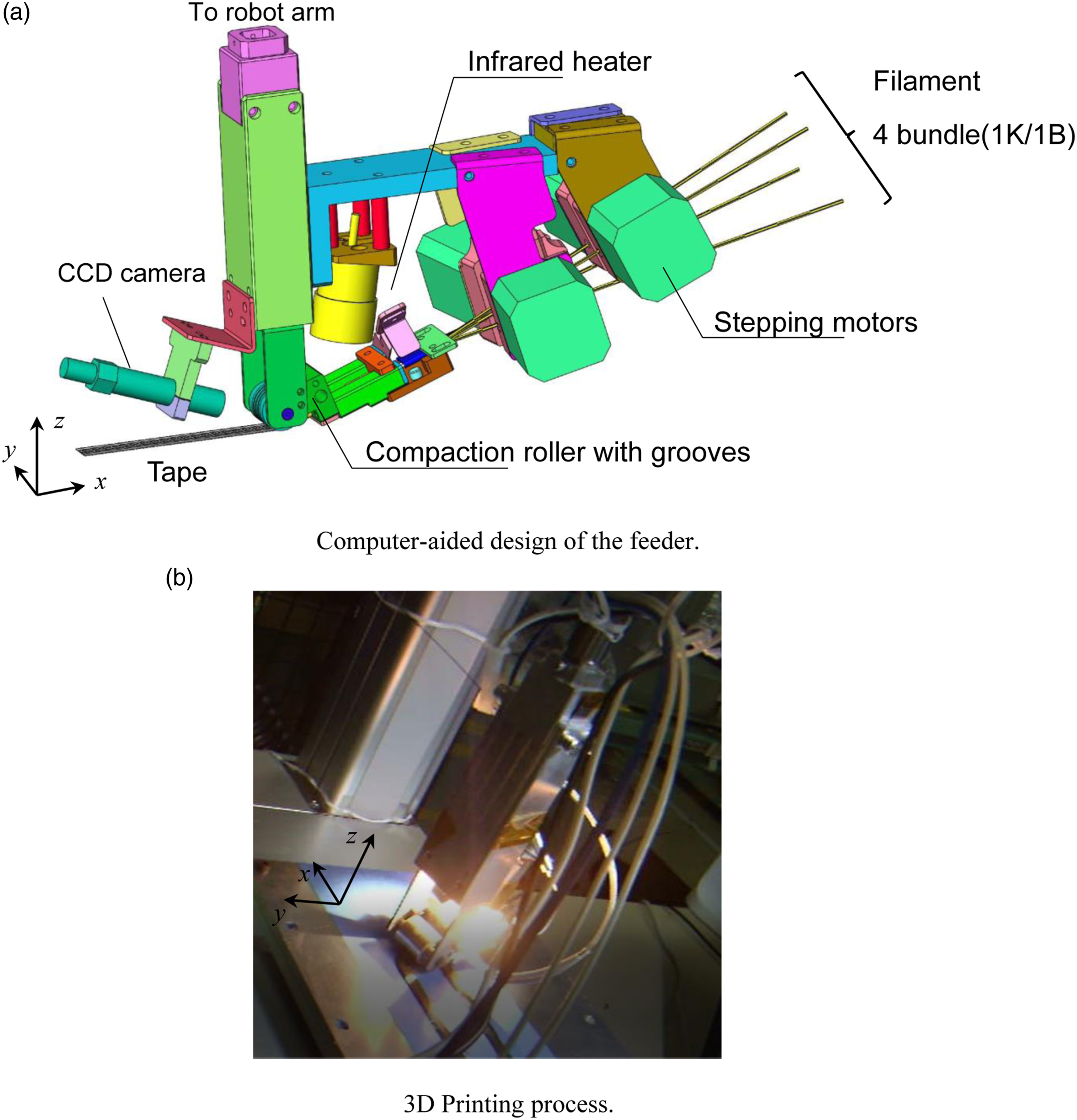
In the curved print path, the travel distance depended on the radius position (Figure 5). Four filaments were fed to the feeder and were supplied separately by controlling their feeding speed using stepping motors that were dependent on the radius position. Difference in the print-path distance in the curved section.
To improve the consolidation, a compaction roller was installed.
16
The filaments were fed to the compaction roller through guided tubes (Figure 6(a)). The compaction roller had hour semicircular grooves on the surface (Figure 6(b)) which maintained the filament positions during printing. The spacing between each semicircular groove was 1.0 mm, which was wider than the filament diameter since the compaction force spreads the filament. The four filaments were heated using an infrared heater immediately before being fed to the compaction roller. Compaction roller with grooves (a) View from the bottom of the multifilament feeder (b) dimension of the compaction roller.
Figure 7 shows a 3D-printed continuous carbon fiber–reinforced thermoplastic composite fabricated using a single path. The print width of a single path was approximately 5 mm. The compaction roller had grooves which created an uneven surface on the 3D-printed composite. This unevenness was resolved by printing the subsequent layer, although it remained on the final layer. Uneven surface of the 3D-printed continuous carbon fiber–reinforced thermoplastic composite due to grooves on the compaction roller.
Print parameters
The Infrared heater was controlled to heat the compaction roller to 275–300°C, which was set to be higher than the melting temperature of PA6 to keep the temperature during printing. The temperature of the build table was not controlled. The pressing force of the compaction roller on the build table was 2.5 kg/cm2. The print speed was 200 mm/min.
Flexural test
Three-point bending tests were performed for 3D-printed continuous carbon fiber–reinforced thermoplastic composites to measure flexural modulus. The test was based on ISO 14,125 except for the specimen dimension. The reduced dimension of the test specimen was 70 × 5 × 1 mm (length × width × thickness). Carbon fibers were aligned to the length direction. The infill of the specimen was 100%. A three-point bending test was performed on the samples under dry and wet conditions. The samples were immersed in 90°C water for 7 days.
Results and Discussion
The flexural test results (Table 1) revealed that under both dry and wet conditions the flexural modulus increased until a PA6 weight ratio of 0.39. The flexural modulus of the 3D-printed unidirectional carbon fiber–reinforced thermoplastic composite samples was affected by the matrix modulus due to the relatively large fiber waviness and twisting.15,16,18,19 After water immersion, the maximum flexural modulus was obtained (23 GPa) at an MAPP weight ratio of 0.08 (Table 2). An appropriate amount of MAPP was needed to prevent the degradation of the flexural modulus due to water immersion. Although the degradation of the flexural modulus was prevented, the flexural modulus under dry conditions at this MAPP weight ratio was 29 GPa, which was lower than the expected (tensile) modulus obtained by the rule of mixture method (92 GPa). This reduction can be attributed to the relatively large fiber waviness and twisting.
The SEM results revealed that the mean particle sizes of the PA6 in the blended polymers depended on the MAPP weight ratio which affected the polymer distribution in the continuous carbon fiber–reinforced thermoplastic composites. An increase in MAPP reduced the particle size of the PA6. The particle size was also affected by the polymer blending process because the shearing force in the blending process reduced the particle size. At the optimum PP: PA6: MAPP weight ratio (0.53:0.39:0.08), PA6 covered well the carbon fibers, which were encompassed by PP. The “jacket” multilayer structure afforded both good adhesion to the carbon fiber and water resistance (see the schematic images in Table 2). Small particle sizes of PA6 and an appropriate weight ratio were important to obtain the “jacket” multilayer structure. The EDS results revealed that the carbon fiber was covered by nitrogen in the PA6 (Figure 8). This result further confirmed the multilayer structure obtained by polymer blending. Here, the oxygen was distributed more on carbon fiber surfaces, which indicated a high concentration of MAPP because of the high polarity of the carbon fiber surface. The MAPP was not only located between PA6 and PP but distributed in the polarity/non-polarity interfaces. EDS mapping around the carbon fiber. Carbon (C), nitrogen (N), and oxygen (O) are represented in blue, green, and purple, respectively.
3D printing was performed to validate high-throughput printing. The L-shaped configuration was printed (Figure 9). The radius of curvature of the corners was 5 mm. The feeding speeds of the four filaments varied depending on the curvature radius of each filament location. The width of the L-shaped configuration, which was obtained using a single path, was 5 mm. Four filaments were fed to the feeder which quadrupled the print speed compared with that of the conventional single-filament feeder system. The print speed of the developed system was 200 mm/min, thus resulting in a modeling speed of 0.9 kg/h. The molding speed was accelerated by parallel printing using a multifilament feeder system. 3D printing of the L-shaped configuration.
Conclusions
A multifilament feeder was developed which demonstrated high-throughput 3D printing of continuous carbon fiber–reinforced thermoplastic composites. To increase the modeling speed, four filaments were supplied to the feeder and printed simultaneously, which quadrupled the manufacturing volume. A modeling speed of 0.9 kg/h was achieved, and wrinkles were not observed by changing the feed speed of each filament. High-complexity or high-throughput printing can be achieved by controlling the number of filaments supplied during 3D printing.
A water-resistant matrix for a continuous carbon fiber–reinforced thermoplastic composite filament was also developed by polymer blending. PP and PA6 were blended using a twin-screw extruder to take advantage of their water resistance and good adhesion to the carbon fiber, respectively. The pultrusion technique was employed to obtain the continuous carbon fiber–reinforced thermoplastic composite filament. The small particle size of PA6 and the appropriate weight ratio were important to obtain the “jacket” multilayer structure. A three-point bending test was performed on the samples under dry and wet conditions. The multilayer structure minimized the degradation of the flexural modulus of the 3D-printed continuous carbon fiber–reinforced thermoplastic composite even after 7-days immersion in 90°C water.
Footnotes
Acknowledgements
This work was supported by FUJIFILM Business Innovation Co.
Declaration of conflicting interests
The author(s) declared no potential conflicts of interest with respect to the research, authorship, and/or publication of this article.
Funding
The author(s) received no financial support for the research, authorship, and/or publication of this article.