
Abstract
This study proposed a novel hybrid joining technique that combines through-thickness reinforcement (TTR) and induction welding methods to address the challenges of composite-metal joining. The effects of geometrical parameters of micro-pins on the formation and bearing performance of hybrid joints were investigated by combing the experimental and numerical simulation approaches. Two simulation models which included the induction heating transfer and joint tensile failure process were established by COMSOL Multiphysics and Abaqus/Explicit. Subsequently, digital image correlation (DIC) was used to monitor the deformation process of different types of joints under tensile load, and a scanning electron microscope (SEM) was used to observe the welding interface of failed joints. By comparing the experimental and simulation results, it is found that adding pins can significantly improve the mechanical performance of welded joints, with maximum increases of 159% and 1758% in ultimate strength and energy absorption respectively compared to welded joints without interlock structures. This technique presents a potential solution for achieving high-quality metal-composite welded structures.
Keywords
Introduction
Due to high specific strength, better fracture toughness and excellent corrosion resistance, carbon fiber reinforced polymer (CFRP) have been widely used in the aerospace, marine and automotive industries. 1 Carbon fibre reinforced composites can be divided into thermoset composites and thermoplastic composites based on the properties of the matrix. In recent years, thermoplastic composites have increasingly replaced thermoset composites in many applications due to their shorter processing cycles, better recyclability and higher repair potential. However, in many applications, such as aerospace and automotive, fully composite structures may be economically unrealistic, so composite-metal joining still plays an important role in achieving high performance joint structures. 2 Currently, thermoplastic composite welding has emerged as an alternative to CFRP-metal joining due to the ability of the thermoplastic matrix to repeatedly melt and solidify.3,4 Compared to mechanical joining and adhesive bonding, thermoplastic composite welding can provide lighter joints and shorter forming times. Common methods for thermoplastic composite welding include: resistance welding, induction welding and ultrasonic welding. Among them, induction welding is considered to be a more effective method for achieving CFRP-metal joint structures, as it has the advantages of higher heat generation efficiency and less impact on non-welded areas.
Recently, extensive research on CFRP-metal induction welding technology has been conducted by researchers. Pappadà et al. 5 analyzed the formation mechanism of thermoplastic composite-metal induction welded joints, showing that the manufacturing process, surface treatment and welding temperature have important effects on the tensile shear strength of the joint. Irene et al. 6 presented a comparative evaluation of ultrasonic, induction and resistance welding of CF/PPS specimens, including an analysis of the mechanical behaviour of the joints, concluding that the load-bearing capacity of induction welded joints is close to that of ultrasonic welded joints. Rudolf et al. 7 investigated the effect of heating parameters and coil shape on heat transfer during induction welding of thermoplastic composites. The results showed that higher welding power can reduce the welding time but also produce a greater temperature gradient across the thickness of the composite, which can lead to resin degradation at the composite surface. Mitschang et al. 8 used an induction welding technique to create an Aluminum and CF/PA66 joint and investigated the effect of pretreatment methods, joining temperature and joining pressure on the mechanical properties of the joint. Nagarajan et al. 9 analyzed the welding mechanism of hybrid joints, the mechanical properties and microstructure of induction welding joints were reviewed in detail. The above studies have shown that the temperature distribution during induction welding has a significant effect on the performance of the welded joint. However, the lack of interlocking structure in the cured adhesive layer will result in a lower load-bearing capacity of the welded joint.
To further enhance the load-bearing capacity of the CFRP-metal hybrid joint, scholars continued to develop through-thickness reinforced joining (TTR) technique,10,11 which the specially designed metal micro-pins are used as fasteners to reinforce the joining interface. For example, Li et al. 12 presented a micro-macro mechanical finite element model to predict the ultimate strength and failure modes of Composite-Metal-Weld (Comeld) joints. It demonstrated that higher joint strength could be achieved by altering the density and height of the metal protrusions. Fei et al. 13 developed an ultrasound-guided Z-pinning process (UAZ), which can insert Z-pins with a diameter of 0.11 mm into composites. The experimental results indicated that Z-pins generate minimal in-plane damage within the composite laminates, and significantly enhance the interlaminar performance of the composite materials. Feistauer et al. 14 studied the ultrasonic vibration heating method to assemble pinned metals with CFRTP (carbon fiber reinforced thermoplastic composite), which was shown very short assembly times and better mechanical performance. Furthermore, Ucsnik et al. 15 used small spikes made by cold-metal transfer method to weld onto the metal surface, which then build up a fiber-friendly fixation through form-closure with co-cured composites. The results showed that the shape of the pin has an important effect on improving the damage tolerance of the joint. As demonstrated by the above studies, it can be seen that the overall performance of the joint can be improved by introducing a properly designed mechanical interlocking structure at the composite-metal joining interface.
However, to the best of the authors’ knowledge, few studies have been conducted on the forming process of TTR-induction welded hybrid joints, and the influence of the structural design of the pins on the failure behaviour of induction welded joints remains unclear. Therefore, in order to improve the joining performance of thermoplastic composite-metal induction welded joints, this paper proposes a novel hybrid joining method that combines the advantages of induction welding and TTR joining. Experimental and numerical simulation analyses of the formation and failure mechanism of CF/PPS-metal induction welded through-thickness reinforced hybrid joints were carried out. In this study, the load-displacement relationships and the formation characteristics of the joints were discussed in detail, with particular emphasis on the effects of the geometrical parameters of the pins, especially the height and number of micro-pins, on the failure processes and modes of the welded joints. In addition, the influence of the temperature distribution at the welding interface on the formation and bearing performance of the joint was investigated. The results of this study provide a novel perspective for the future development of high strength CFRP-metal welded joints.
Experimental test methodology
Test specimen preparation
The CFRP plates were manufactured using resin transfer moulding. The carbon fiber reinforced thermoplastic composite (CFRTP) specimen was made by T300JB/PPS 5HS (harness satin) twill-woven fabric CFRP, which has 25 piles and a thickness of 5 mm, the single layer thickness is 0.2 mm. Based on the fiber and fabric properties specified by the manufacturer,the fabric ply surface weight is 0.6 kg/m2,the fiber density and fiber diameter are 1790 kg/m3 and 7.1 μm respectively.
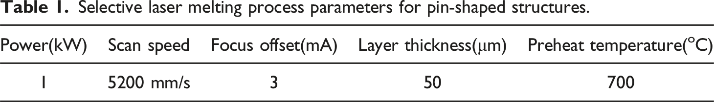
Selective laser melting process parameters for pin-shaped structures.
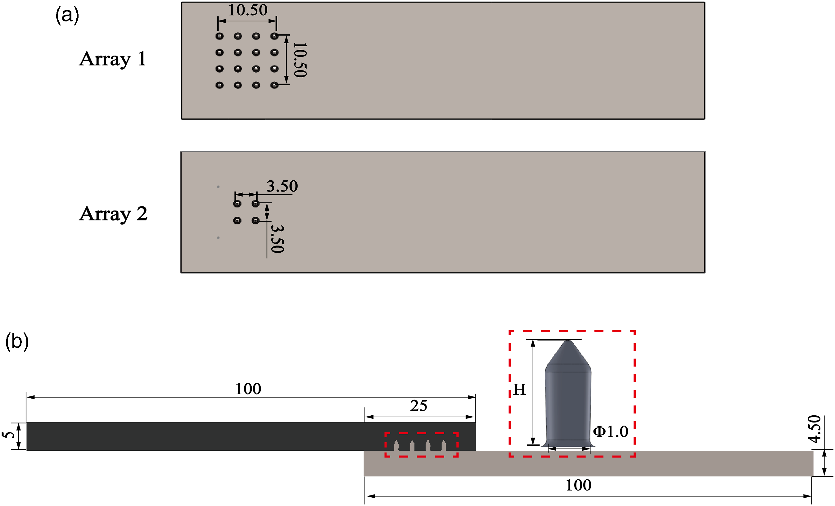
Detailed image of joined specimens (measurements in mm) (a) two types of pin arrays on metal surface, (b) geometric parameters of specimen and pin structure (H: pin height (1 mm and 3 mm); the diameter of the pins is 1 mm).
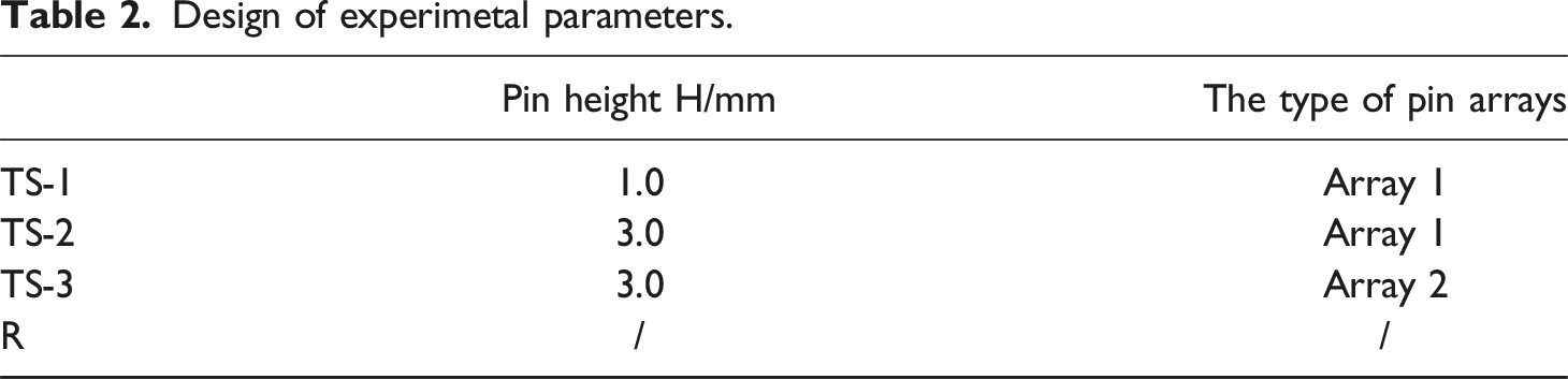
Design of experimetal parameters.
Joining procedure and experimental set-ups
The induction heating process was carried out in a specially designed device, as illustrated in Figure 2. The device comprises three modules: a fixed holder, a pressure application device consisting of a pressing tool and a spring gauge, and an induction heating device. The sample holder used to join CFRTP specimens and pinned stainless steel substrates is presented in Figure 2(a). To maintain balance, four springs are placed on the rear side of the stainless substrate. Next, the initial pressure is applied to the pressing tool to transfer the force to the welding zone. The entire induction heating process is divided into three phases: heating, holding, and cooling. During the heating and holding phases, the input current of the equipment was set to be 400 A and 275 A, respectively, with a current frequency of 65 kHz, and the distance between the specimens and the coil is about 5 mm. The duration of the heating phase is 2 min, The holding times for TS-1, TS-2, and TS-3 joints are 8 min, 23 min, and 16 min respectively. The cooling time for all types of joints is set to 2 min. The temperature variation during the joint forming process was monitored using a K-type thermocouple, and the location of the temperature sampling points is shown in Figure 2(a). (a) Layout of the sample holder used to produce the welded joints, (b) a detailed site view of joint assembling system.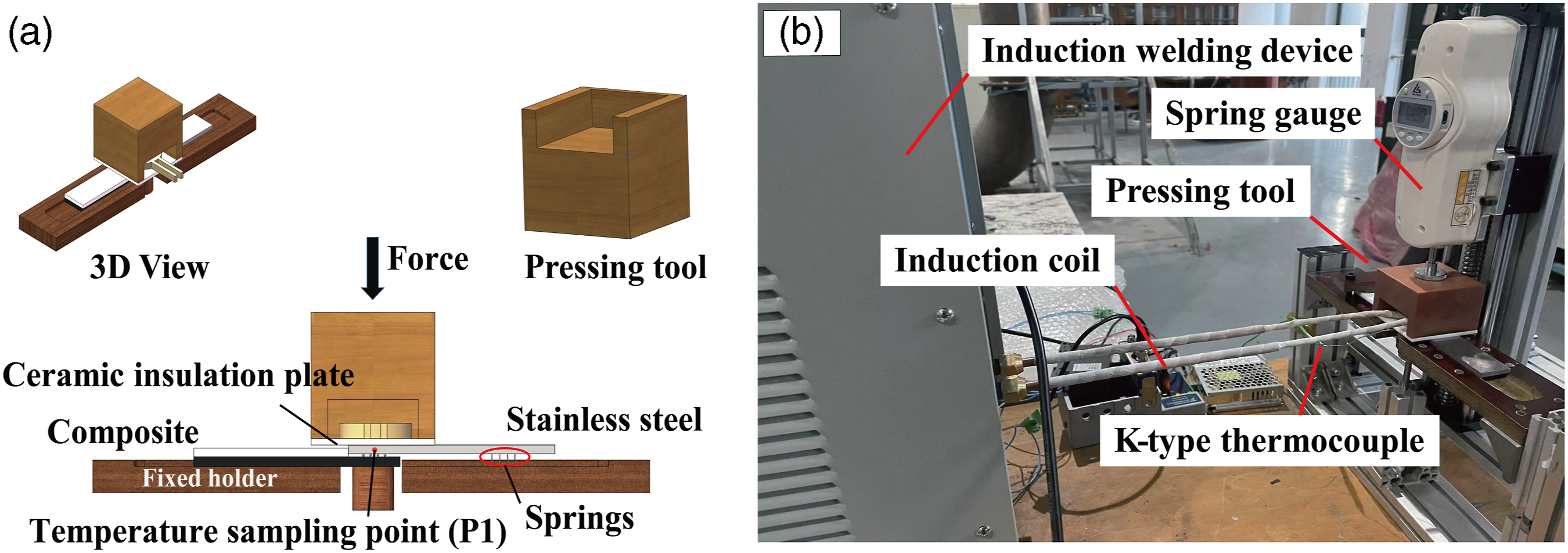
The formation process of TTR-induction welding joints can be divided into four phases. In phase 1, as shown in Figure 3(a), (a) constant force (F0 = 70N) was applied on the pressing tool to ensure stable contact between the welded samples. After that, the welding current was linearly increased to 400 A until the temperature of the temperature sampling point (P1) reached 360
o
C, as shown in Figure 3(b). As soon as the welding temperature was reached, a joining force (F = 200N) began applying, the welding current was decreased to 275 A and the welding temperature was controlled at 360
o
C during the holding phase. Then the polymer below the pins started softening, and pins were gradually embedded into the melted composite laminate, as is shown in Figure 3(c). Once the pins were fully embedded, the induction welding equipment was turned off to enter the polymer consolidation phase (Figure 3(d)). During this phase, a consolidation force (F
w
= 300N) was applied on the joint and held for minutes to ensure polymers were fully consolidated. Schematic representation of the formation process of the SLJ (a) positioning of joining parts, (b) start heating and application of axial force, (c) softening of the composite matrix and onset of pin penetration, (d) polymer consolidation.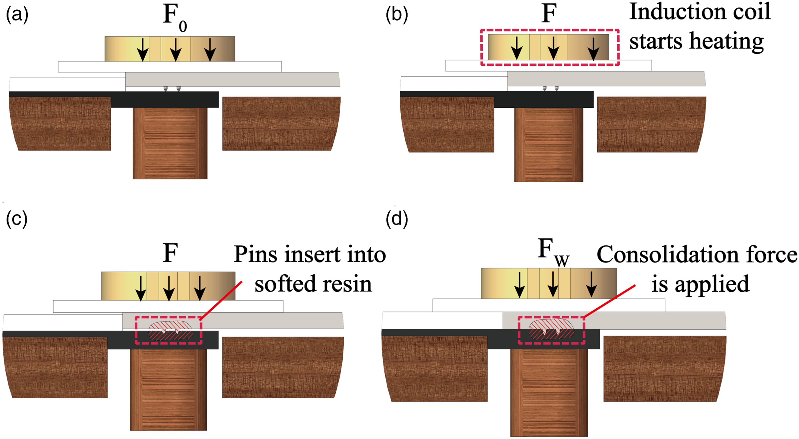
Tensile tests were conducted on a universal material testing machine following the test standard of ASTM D5868-2001 (R2014), 19 the tensile speed was 1 mm/min. In this case, three repetitions of tensile tests were carried out for each type of single-lap joints. A 3D digital image correlation (DIC) system (ARAMIS, GOM, Germany) was utilized to measure surface strain distribution and deformation of the joints during the tensile process. KEYENCE VHX-1000 digital microscope and SIGMA300 scanning electron microscope (SEM) were used to observe the surface damage after tensile testing.
Numerical modeling
To analyze the effect of pin geometrical parameters on the performance of welded joints, in this paper, the simulation model of the induction heating transfer process was established by COMSOL Multiphysics V6.0. The joint tensile failure process was simulated by using Abaqus/Explicit V6.14.
Finite element modeling of induction heating transfer process
To simplify the simulation process, the model does not contain the pin embedding process. The simulation model and boundary conditions for the induction heating process are shown in Figure 4. In this model, the coil is modeled as a homogenous two turns of coil domain in COMSOL with a diameter of 7 mm. The air domain is a rectangular area with 200 mm long, 100 mm wide, and 100 mm high, and the outer boundary of the air domain is specified as a magnetically insulated boundary condition, as is shown in Figure 4(a). The mesh distribution in the model is shown in Figure 4(b) and Figure 4(c). The value of input current and current frequency is consistent with the experimental design. Finite element model for simulating the distribution of the temperature during the induction welding process.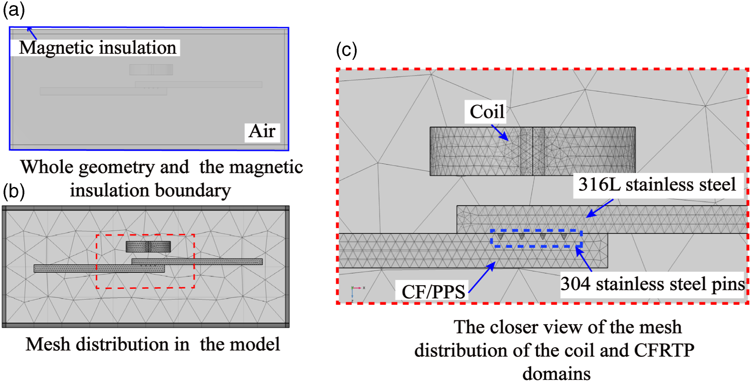
The induction heating transfer model takes into account the multi-physics field coupling between electromagnetic field and heat transfer. The principal equations of the electric and vortex fields can be expressed as follows:

Due to the skin effect caused by the high frequency of the magnetic field, the distribution of eddy currents in the stainless steel is not uniform. The distribution of the eddy currents within the metal specimen can be expressed as:
Where J0 is the current density on the metal surface, J
d
is the current density at a distance d from the metal surface, The penetration depth δ can be computed by: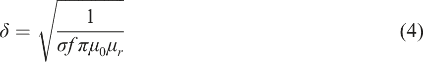
The stainless steel generates an induced current under the action of the electromagnetic field, and its current density field is calculated by: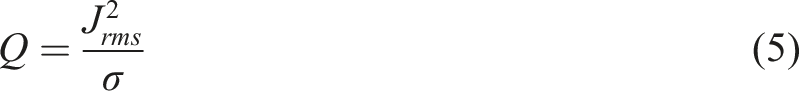
The thermal problem is defined by the heat transfer equation:
The equation (7) defines the heat transfer between the external surfaces of all components and the surrounding air through convective boundary conditions.
Finite element modeling of joint tensile processs
The 3D finite element (FE) model of the welded joint is shown in Figure 5(a). The model geometry is consistent with the experimental test specimens, with one end of the joint completely fixed, while the other end is subjected to tensile loading. In order to improve the simulation efficiency, the sections of the metal and CF/PPS away from the micro-pinned region were meshed using an element size of 5 mm. Following the mesh optimization test, a refinement of the mesh (mesh size range: 0.15 mm-1 mm) was performed on the micro-pinned region in the CF/PPS and 316 L stainless steel substrate. The micro-pins were meshed with a global element size of 0.125 mm. All parts were modeled using eight-node linear hexahedral elements with reduced integration and hourglass control. FE models of the SLJs with SLM pins (a) meshes and boundary conditions, (b) detail view of region (a)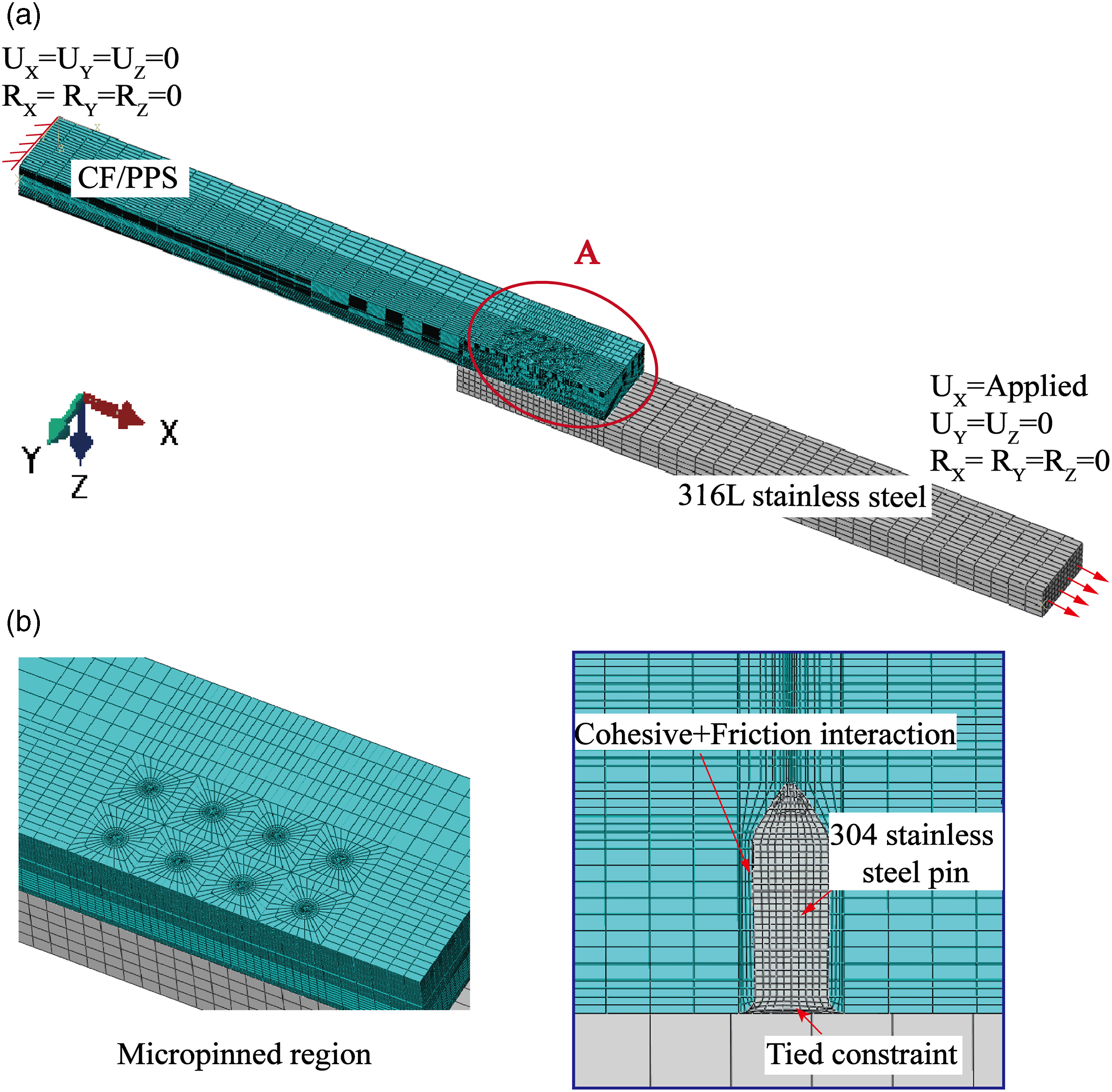
The contact definition of the pins with the metal specimen is shown in Figure 5(b). The bottom surfaces of the pin and the 316 L stainless steel are connected together with tied constraint. Cohesive contact interaction coupled with coulomb friction/contact pressure relationship is used to simulate the welding interface between the micro-pin and CF/PPS. In the induction heating process, it is believed that the welding interface has the same mechanical properties. Therefore, a unified failure parameter is used to simulate the failure process of the welding interface. As shown in equation (8), the linear elastic model is used to define the elastic response of the interface before the damage initiation: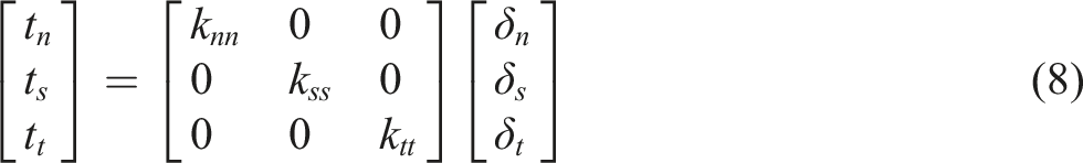
Using the quadratic stress criterion
28
to model interface damage, the damage is considered to initiate when the contact stresses reach the following condition: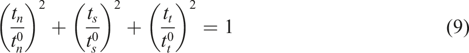
The energy-based Benzeggagh-Kenane (B-K) criterion was used to describe the evolutionary behavior of the damage after its initiation. The total energy of fracture is given by the following equation29,30:

In the presented model, the CF/PPS specimen was modeled as orthotropic material. The material stress-strain relationship, damage criterion, and damage evolution law are implemented using the Abaqus user-defined material subroutine VUMAT. In order to better simulate the elastic-plastic deformation process of the pins, the 304 stainless steel was modeled using the Johnson-Cook model,
24
with the governing equation expressed as:
Fracture in the 304 stainless steel was analysed with the governing equation expressed as:
Results and discussion
Finite element model validation
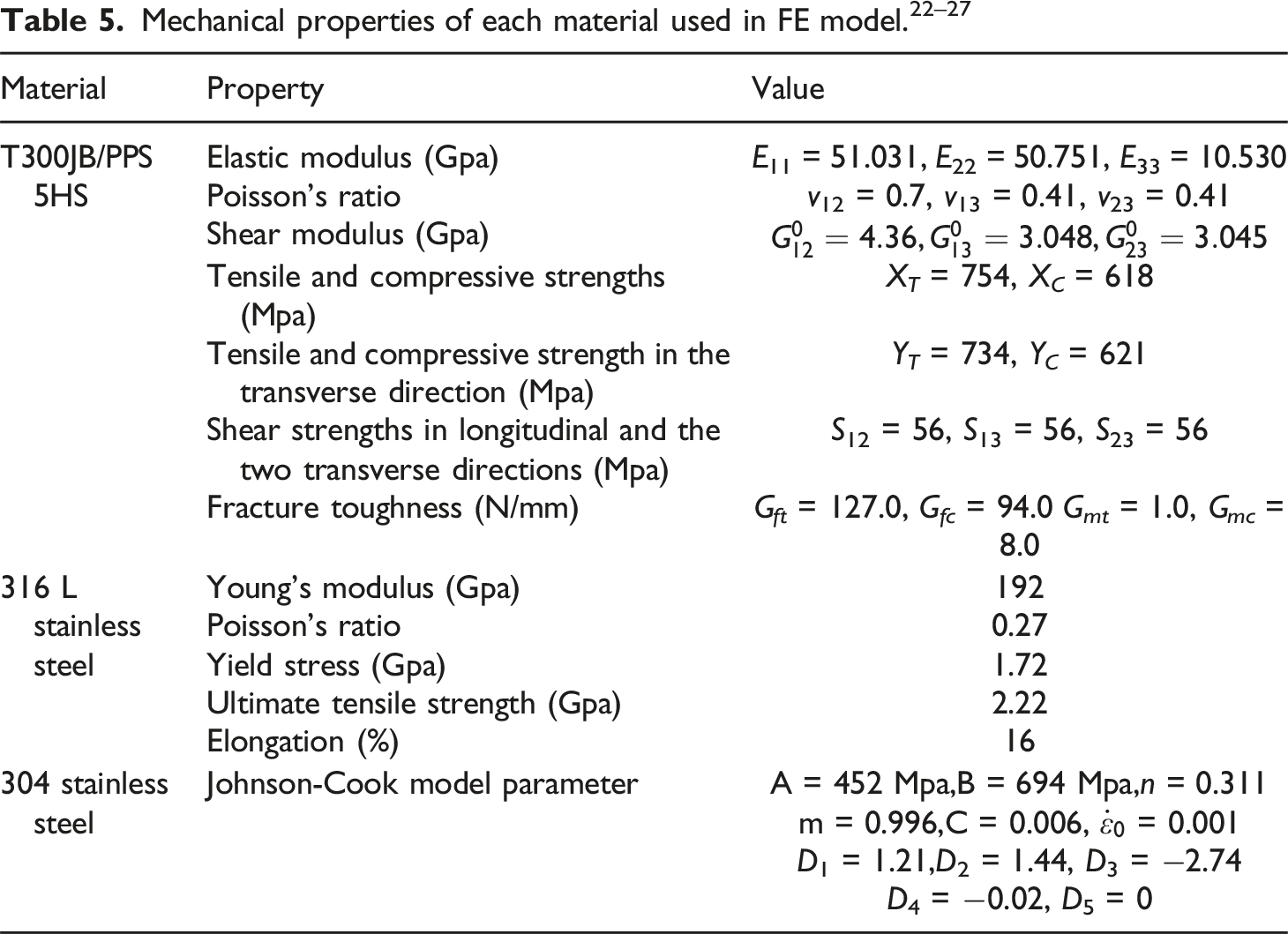
The experimental and simulation results of temperature variations at the measurement points are illustrated in Figure 6. As seen in the figure, the simulation results closely match the experimental result both in terms of magnitude and variation pattern. The maximum prediction error for the proposed simulation model is 4.6%. Thus, it can be seen that the induction heating transfer model can accurately predict temperature distribution during induction welding. For the three different types of joints, the welding time required for joint formation is as follows: 12 min for TS-1, 27 min for TS-2, and 20 min for TS-3. Comparing between experimental and simulation results of temperature variations at the temperature sampling points (P1).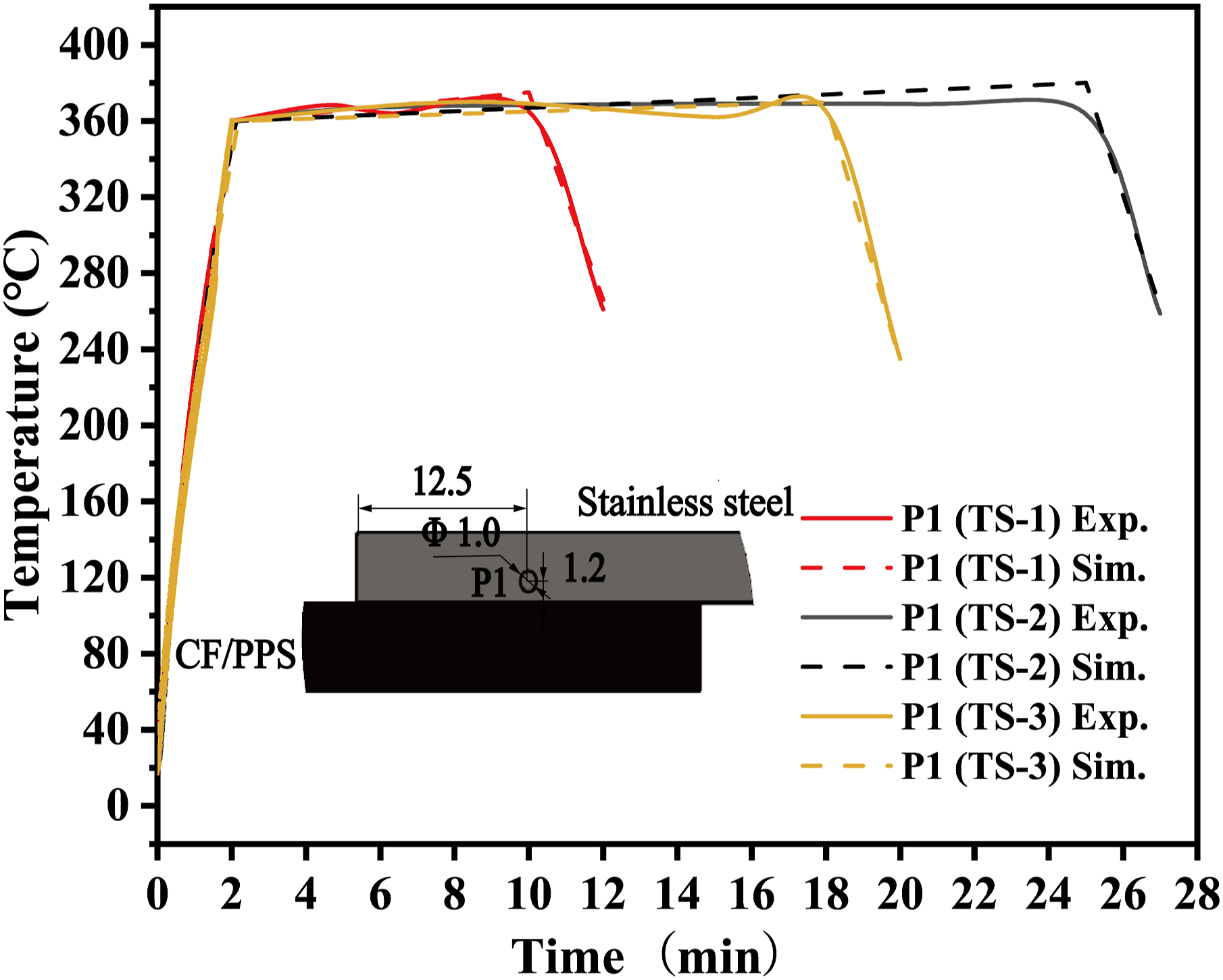
The simulation results of the temperature variation at different locations of the welding joint are presented in Figure 7(a). From the Figure, it can be observed that the temperature rise rate at P1 (316 L stainless steel substrate) is faster than other welding points during the heating phase. In the cooling phase, the temperature of P1 in the metal substrate and P2 in the metal pin decreases rapidly, while the temperature of CF/PPS at P3 decreases gradually after the rapid increase. Figure 7(b) illustrates the thermal generation in the welding joint, it is found that the heat in the metal substrate is mainly concentrated on the side near the coil due to the skin effect, the mental substrate acts as the heat source for conducting heat to the CF/PPS material and pins. Moreover, it can be observed from Figure 7(b) that there is a significant discrepancy in heat generation between P1 (316 L stainless steel substrate) and P2 (metal pin) during the initial stage of induction welding. Notably, relatively lower levels of heat are generated at P3 (CF/PPS). These findings indicate that both pins and CF/PPS exhibit minimal induction heat generation under electromagnetic field influence comparing with metal substrates. Figure 7(c) is the simulation results of the temperature distribution in the welded joint, it is evident that the maximum temperature within the metal substrate exceeds 400
o
C as the welding time increases to 10 min. However, the highest temperature within CF/PPS is no more than 120
o
C. During the cooling phase, a greater amount of internal heat from the metal is transferred to the CF/PPS material due to the increased thermal contact area, which can significantly raise the temperature of the resin closed to welding zone and ultimately promote forming the welding surface. (a) simulation results for the temperature variation at different locations of the welding joint, (b) contour plot of heat generation, (c) temperature distribution during the welding process.
The load-displacement (L-D) curve for the typical tensile failure process of the single lap joints is shown in Figure 8(a). The simulation results demonstrate satisfactory consistency with the experimental results. The mechanical properties of different types of joints are demonstrated in Figure 8(b)–(d). The blue dashed line indicates the mechanical properties of the welded joint without pins(R). The failure work W
f
is used to access the joint’s energy absorption capacity. Comparison between numerical and experimental results of the single-lap joints mechanical properties (a) load–displacement response of the welded joints, (b) ultimate load, (c) maximum displacement, (d) energy absorption.
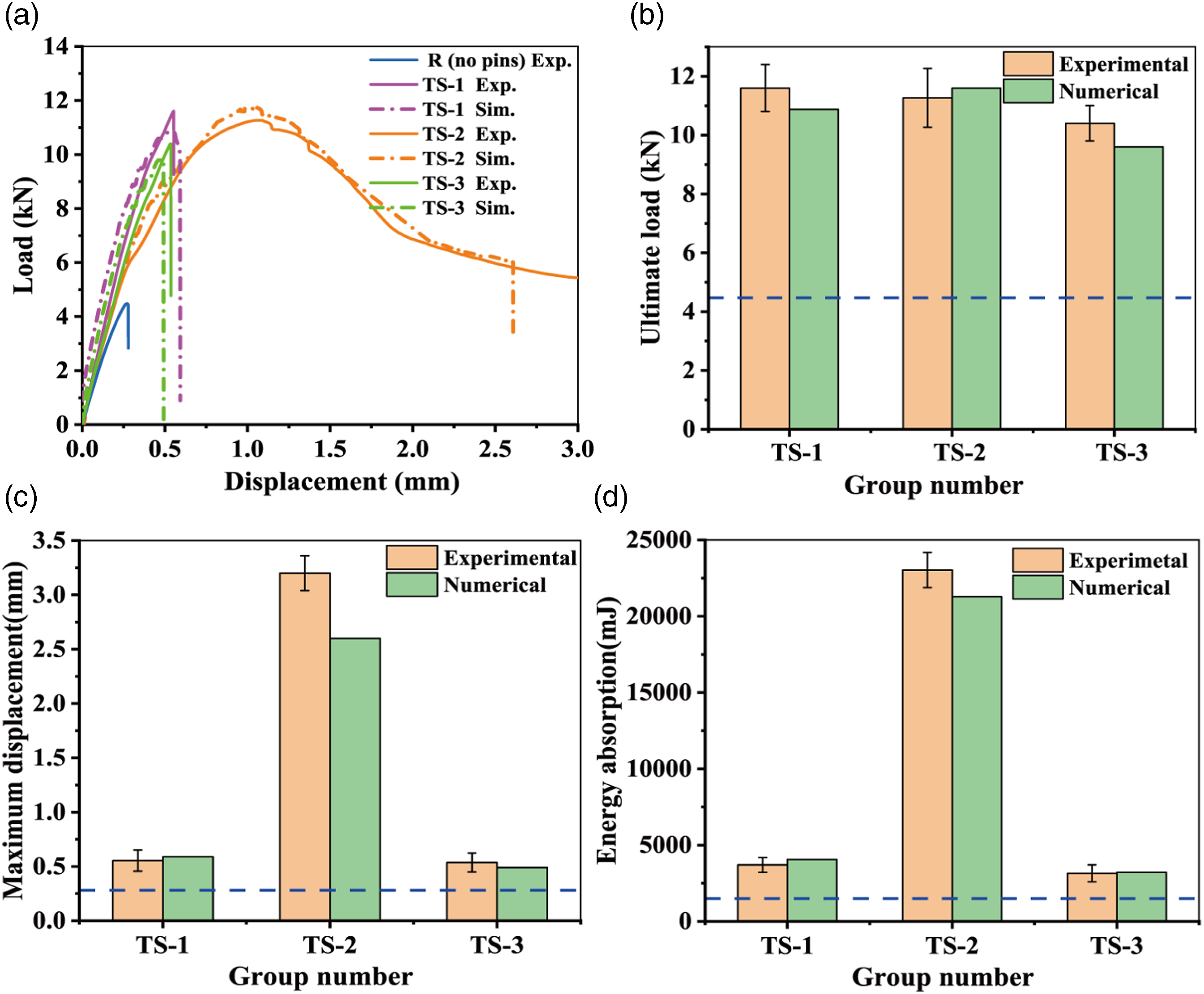
From the figure, it can be obtained that the maximum error of the simulation results is 6.21% for the ultimate load, 18.75% for the maximum displacement, and 9.62% for the energy absorption. Therefore, it can be inferred that the model proposed in this study can accurately predict the tensile failure process of the joint. When the slope of the L-D curve shows non-linear variation, it indicates the occurrence of damage in the joint welding surface. Based on this analysis, it can be concluded from the figure that the different types of joints experience initial debonding at specific joint loads: TS-1 joint at 4.45 kN, TS-2 joint at 5.4 kN, TS-3 joint at 5.65 kN, and joint R (without pins) at 2.6 kN. These results indicate that joints with pins generally experience higher loads for initial damage compared to welded joints without pins.
Effect of pin heights on joint performance
Forming quality of welded joints
According to the microstructure of the joint shown in Figure 9(a), it can be observed that there is a significant resin-rich zone at the welding interface of the TS-1 joint, along with relatively large voids in that area. In addition, slight interface voids were found near the connection interface between the pin and CF/PPS, and no obvious delamination was observed. In the TS-2 joint cross-section shown in Figure 9(b), the void and delamination phenomena were more severe than that in TS-1 joint. The formation of these voids could result from the releasing gas of the PPS resin during the induction welding process and the existence of bubbles and structural water in the CF/PPS. The occurrence of delamination damage is related to the fiber displacement caused by the insertion of the pin into the soften composite material. Therefore, it can be inferred that the above-mentioned damage in the composite materials is closely related to the temperature distribution during induction welding process. Influence of different pin heights on joint installation quality (a) TS-1, (b) TS-2, (c) and (d) are the temperature distribution of the TS-1 and TS-2.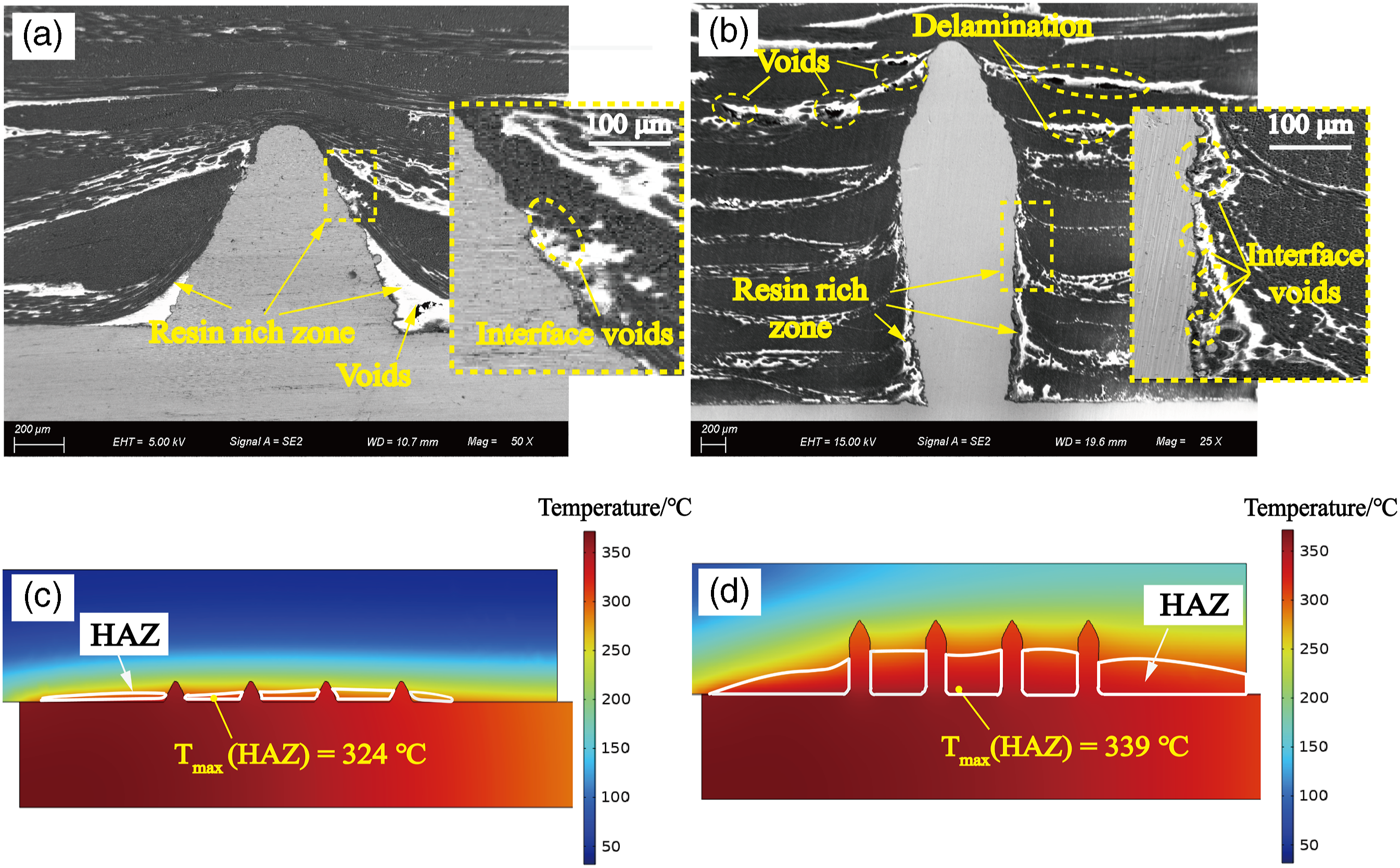
The simulation results of temperature distribution for TS-1 and TS-2 joint interface (after applying the consolidating force Fw to the joints for 15 s) are shown in Figure 9(c) and (d). The white circular region in the figure represents the heat-affected zone (HAZ) within the CF/PPS material, which refers to the area above the melting point of PPS. The simulation results showed a larger HAZ in TS-2 compared to TS-1, and the maximum temperature of HAZ was higher in TS-2 (339 o C) than that in TS-1 (324 o C). This is because the welding time of TS-2 (27 min) was longer than TS-1 (12 min) due to the larger embedding depth, which increased heat input at the welding zone. Comparative analysis of the experimental and simulation results concluded that increasing the height of the pin will further increase the welding time from 12 min to 27 min, which can lead to a larger HAZ within the CF/PPS material. The increased flowability of the thermoplastic matrix in the HAZ is more likely to result in damage within the composite laminates, such as voids and delamination.
Failure processes of carbon fiber/polyphenylene sulfide-metal pinned joint
To gain deeper insights into the failure mechanism of welded joints, a comparative analysis of the deformation mechanism and strain propagation in the welding surface is presented in Figures 10 and 11. From Figure 10, it can be seen that the tensile load of the R joint exhibited linear increase during the early stage of the tensile process. However, a decrease in the slope of the L-D curve was observed when D = 0.13 mm. Subsequently, the tensile load rapidly declined after reaching joint peak load (4.47 kN). The digital image correlation (DIC) results revealed high peel strains on both sides of the welding surface in joint R (D = 0.13 mm). With increasing tensile displacement up to 0.26 mm, the peel strain gradually propagated towards the middle region, and complete interfacial failure of the welding surface occurred when D = 0.28 mm. Joint deformation, strains and damage mechanisms for welded joint without pins (R). (D represents tensile displacement.) Joint deformation, strains and damage mechanisms for different pin heights. (D represents tensile displacement.)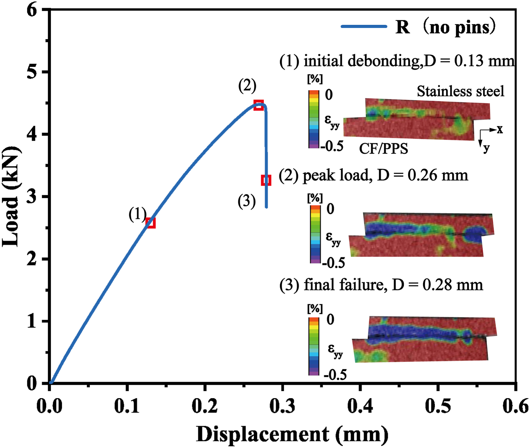
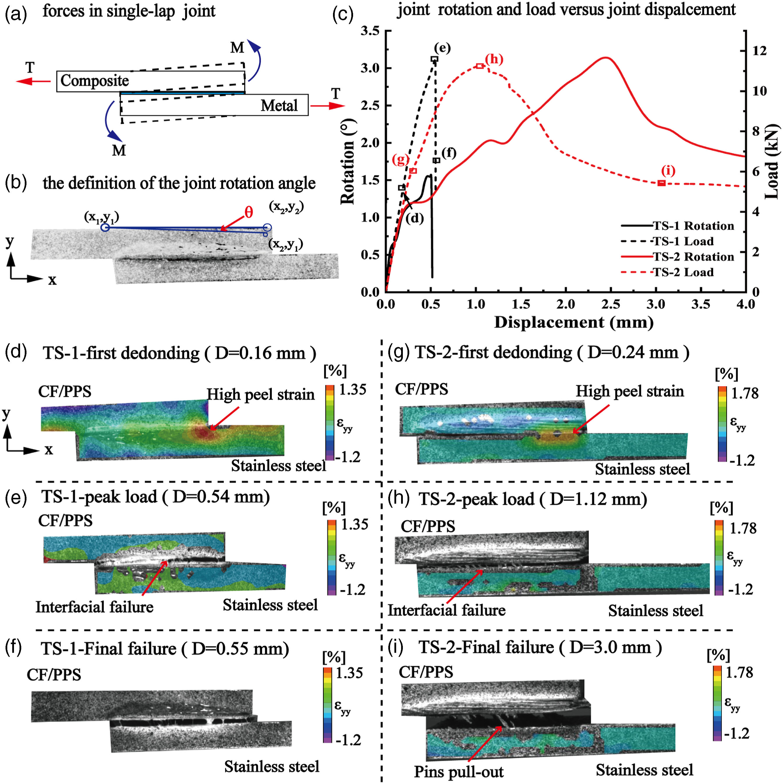
The schematic of a tensile-loaded SLJ is shown in Figure 11(a), where the adherend experiences not only the applied tensile force but also the moment due to the eccentric load path. The combination of these forces results in tensile and bending stresses in the adherend. The definition of the joint rotation angle during the tensile process is presented in Figure 11(b). The variation of joint rotation angle and tensile load with increasing displacement (named R-D and L-D respectively) are shown in Figure 11(c). For TS-1, as shown in the L-D curve in Figure 11(c), the tensile load of the joint exhibited a linear increase with displacement (D) until reaching its peak load of 11.6 kN, followed by a sudden decline, which will lead to the catastrophic failure of TS-1. However, in the case of TS-2, a noticeable reduction in the slope of the L-D curve occurred when D was closed to 0.24 mm, indicating that the initiation of welding surface damage. Compared to the sudden failure of TS-1, the tensile load of TS-2 slowly decreased after peak load (11.27 kN) and gradually stabilized when tensile displacement exceeded 3.0 mm.
Moreover, it can be obtained from the L-D curves in Figures 10 and 11(a) that for the joints without pins (R), the ultimate strength and the strength at the first debonding of the welding surface are measured as 7.15 MPa and 4.16 MPa according to ASTM D5868-2001 (R2014) 19 respectively. The ultimate strength of the joints with pins (TS-1, TS-2) is reported as follows: 18.56 MPa, 18.03 MPa. The joint strength at the initial debonding of the welding surface is recorded as 7.12 MPa, 8.64 MPa for each joint type. The ultimate strength of TS-1 and TS-2 joints increased by 159% and 152%, compared to R joints. The first debonding strength of TS-1 and TS-2 joints increased by 71.2% and 108%, compared to R joints. In addition, it can be obtained from Figure 8 that their energy absorption capacities exhibited an increase of 198% and 1758%, in comparison to R joints (1500 mJ). From the above results, it can be inferred that for induction welding of thermoplastic composites, the addition of micro-pins is an effective method to improve the mechanical properties of the joint. The R-D curves of the joints in Figure 11(c) show that at the beginning of loading, both pinned joints exhibited a linear increase in rotation angle. After the rotation angle of TS-1 reached the peak value (1.5°), the joint rotation angle decreased suddenly. However, the joint rotation angle of TS-2 stayed a progressive trend of dropping after the peak rotation angle (3.2°). The peel strain states (ɛ yy ) of TS-1 and TS-2 were obtained using 2D-DIC and are shown in Figure 11(d)–(i). From Figure 11(d) and (g), high peel strains initially occurred at the free end of the composite material when first debonding occurred at the welding interface. With increasing deformation of the joint, peel strains gradually propagated along the welding surface from the two ends towards the overlap region until the interfacial failure occurred (the tensile load reached to the peak value), as illustrated in Figure 11(e) and (h). Compared to the TS-1 joint (Figure 11(f)), the final failure of the TS-2 joint was delayed until D = 3.0 mm, at which point all the pins were pulled out from the composite material (Figure 11(i)).
The simulation results of damage evolution for TS-1 and TS-2 are shown in Figure 12. Based on the simulation results, the progressive damage sequence of the welded joint with pins was divided into different phases: 1. The start of substrate debonding; 2. The first pin starts to debond; 3. Completion of substrate debonding; 4. The bending deformation and pull-out of the pins. The interfacial damage in the welding surface is quantified using the cumulative strain damage model (CSDMG). The value of 0 indicates no debonding, while 1 indicates complete failure of the welding zone. From the figure, it can be observed that the displacements at the first debonding of the TS-1 and TS-2 joints are 0.16 mm and 0.24 mm, respectively. Before the initial damage occurs in the welded joint, the tensile load is primarily carried by the welding interface. After damage occurred, there is a reduction in the slope of the L-D curve for the joint. For TS-1, it can be obtained from simulation results that the pins near the free end of the composite material began to debond and partially pull out (D = 0.43 mm), which increased the moment of the joint on this side and caused a sharp change in the slope of the L-D curve. Both the pin and the welding interface carried the load during the tensile process until the TS-1 joint reached peak load (D = 0.54 mm), the welding surface failed entirely. After that, the metal pin primarily carried the tensile load, and then all the pins quickly pulled out and underwent slight bending deformation (D = 0.55 mm). For TS-2 (Figure 12(b)), it can be seen that the interfacial damage of the welding surface initiated from two ends and spread to the middle slower than that of the TS-1 joint. The pin experienced first debonding at D = 0.52 mm. Moreover, after peak load (D = 1.12 mm), the welding interface between the metal substrate and CF/PPS has completely failed, however the welding surface around the pins did not completely fail, which indicated that micro-pins still carry some load. As the tensile displacement increased, the pin slowly pulled out from CF/PPS and underwent increased bending deformation (D = 1.5 mm), which meant that a significant amount of energy was absorbed by the pins during the joint failure process. After complete pull-out of the micro-pins (D = 3.0 mm), they will slide along the composite material surface, which can leave long-distance scratches on the welding surface. From these results, it can be concluded that higher pins not only impede the failure process of the welded joint but also transfer more load between the connected parts together with the welding surface, which can ensure the tensile load does not fall rapidly and greatly improve the energy absorption of the TS-2 joint. The damage evolution of CF/PPS-metal joints in various stages of loading.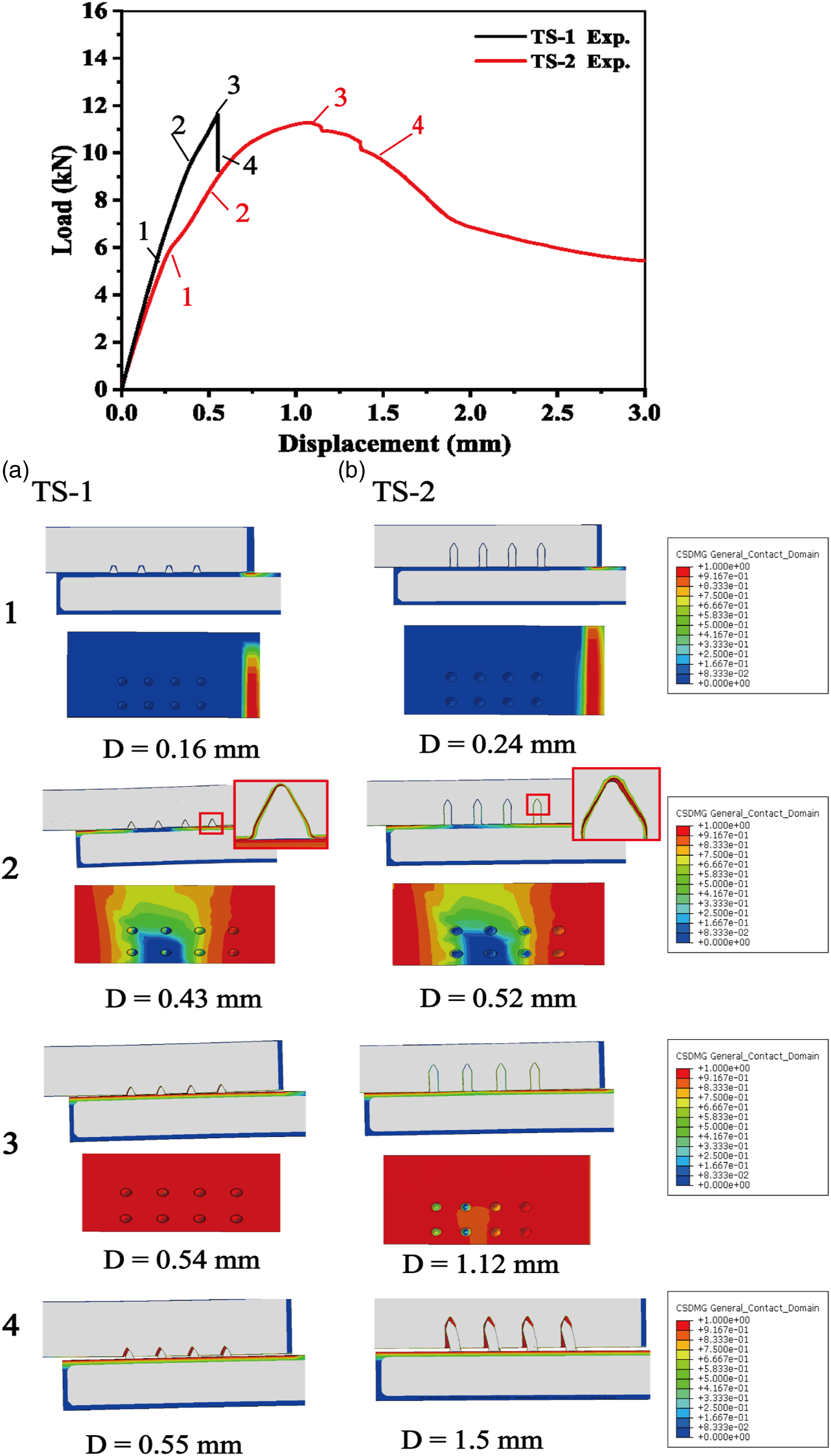
The microstructure of the CF/PPS welding interface after the tensile test is illustrated in Figure 13. From the figure, the red solid line depicts the initial morphology of the hole wall. Based on the SEM results, it can be observed that some of the composite material was damaged after the pins pull-out, which formed a squeezing region on the hole wall (highlighted by the yellow dashed line). The composite damage within the squeezing region mainly involves matrix crushing and fiber breakage. In comparison to TS-1, the TS-2 joint exhibited more significant delamination damage in the CF/PPS after the tensile test. Moreover, the squeezing region in the TS-2 joint is concentrated near the exit of the pin hole, covering a larger area than that observed in the TS-1 joint. Microscopic morphology near the pin hole (a) TS-1, (b) TS-2.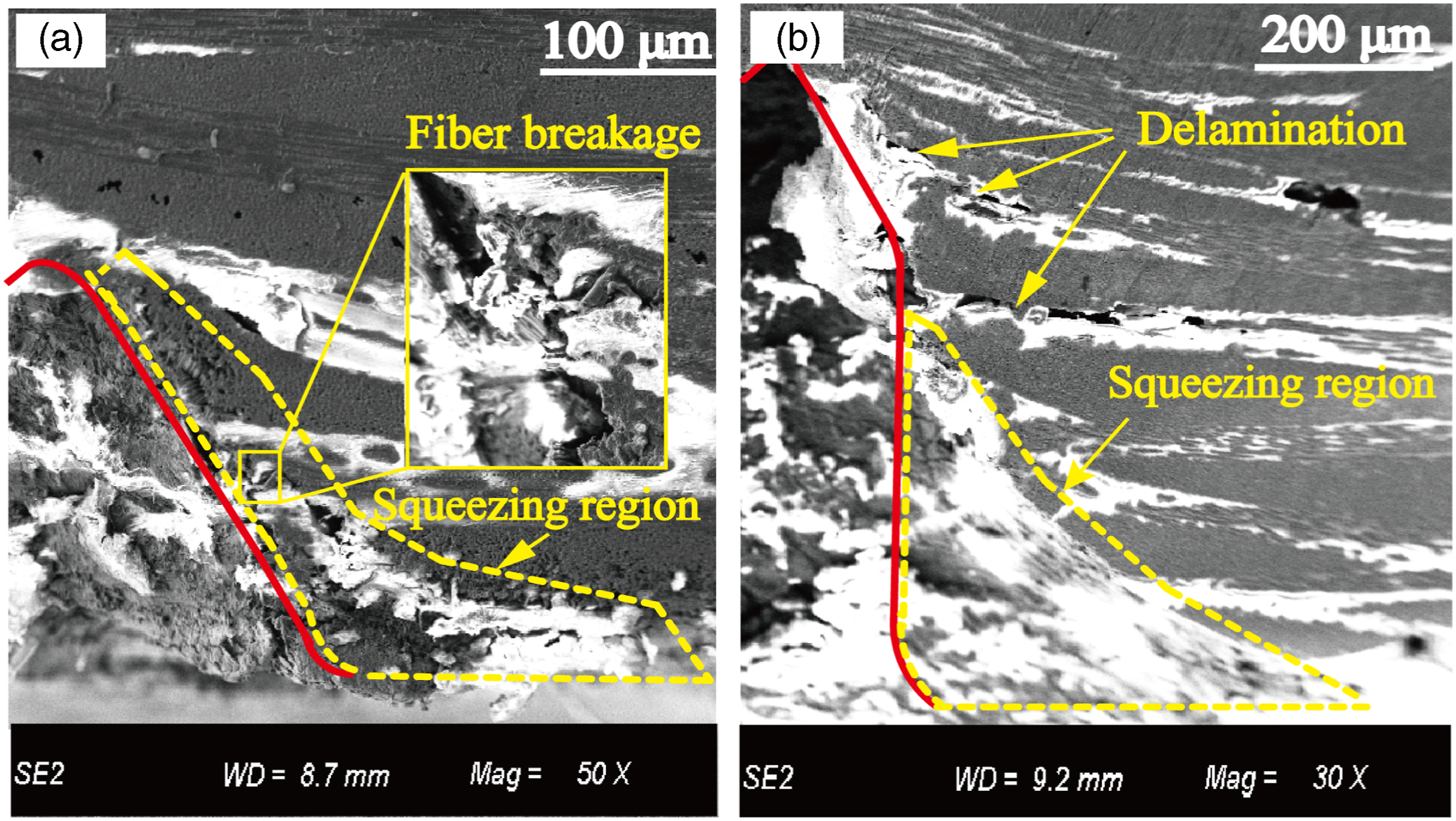
The stress distribution around the single pin at the peak tensile load is presented in Figure 14(a). From the figure, the stress distribution on the hole wall corresponds to the shape of the squeezing region observed in the SEM results. For the TS-2 joint, the bearing stress is mainly concentrated on the exit side of the hole wall, with a maximum bearing stress of 925.5 MPa within the CF/PPS, which is higher than the 582.1 MPa for the TS-1 joint. From these results, it can be concluded that increasing the height of the pin will enhance the bearing stress on the hole wall during the joint failure process, which will lead to composite damage and affect the integrity of the matrix and fiber. From the Figure 14(b), it is founded that the maximum normal and shear stresses carried by the pin 4 are higher than those in the middle region during the tensile progress. The pin 1 carried lower normal stress than the 4th, this is most likely due to the out-of-plane displacement of the metallic part, which bends the pin 1 area out of the joint plane, and pin 1 starts to be pulled out in the overlap area, thus decreasing the stresses at this case. (a) the stress concentration around the single pin at the peak tensile load, (b) the shear stress and normal stress distribution along the joint overlap area (metal side).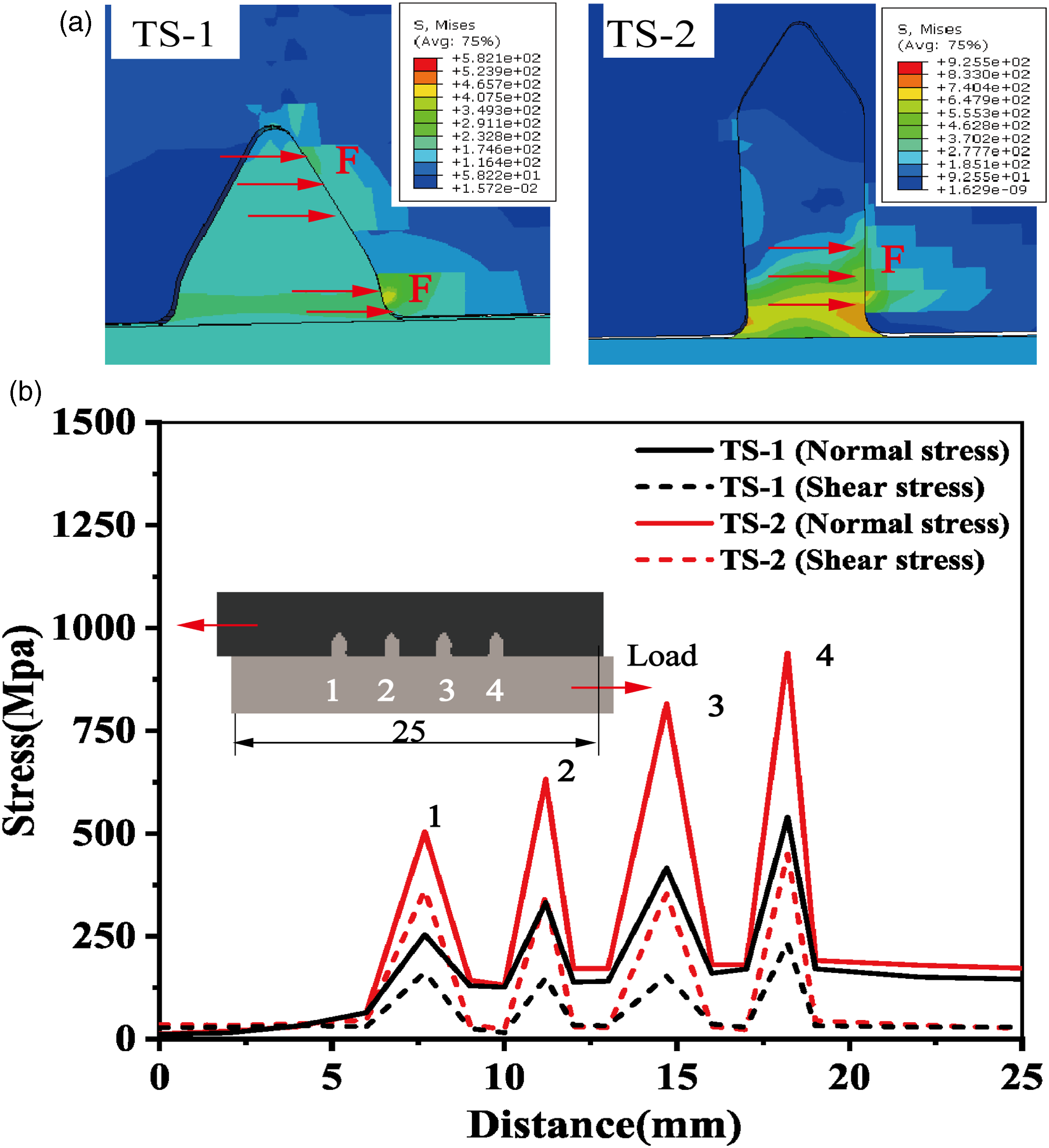
Failure modes of CF/PPS-metal pinned joint
Following the tensile tests, the failure modes of welded joints were analyzed using optical microscopy and SEM technique. The observation results of the failure surface of the welded joints are shown in Figure 15. The typical failure modes were classified into three types based on ASTM D5573-99
31
: fiber-tear failure (indicated by the red boundary), adhesive failure (indicated by the blue boundary), and cohesive failure of the composite surface (indicated by the yellow boundary). The failure surface of the TS-1 joint (Figure 15(a)) revealed that fiber-tear failure was predominantly distributed on the edge region of the stainless steel and CFRTP specimens. Strands of carbon fibers were peeled off the CF/PPS, and torn fibers were observed on the metal substrate. Adhesive failure was observed at the free end of the composite and the corresponding metal side. The composite surface remained relatively intact, and a small amount of resin peeled off, it was indicated that the metal specimen was not fully welded to the composite laminate. Cohesive failure was mainly located at the free end and center regions of the metal substrate, where the fractured fibers and resin were distributed on the metal surface. Fiber-tear failure and cohesive failure both demonstrated that the weld line underwent plastic deformation and absorbed a large amount of energy during the tensile process. The failure surface of the TS-2 joint is displayed in Figure 15(b). Compared to the TS-1 joint, there is no severe adhesive failure observed on the failed surface of the TS-2 joint. Failure surfaces of the welded joints.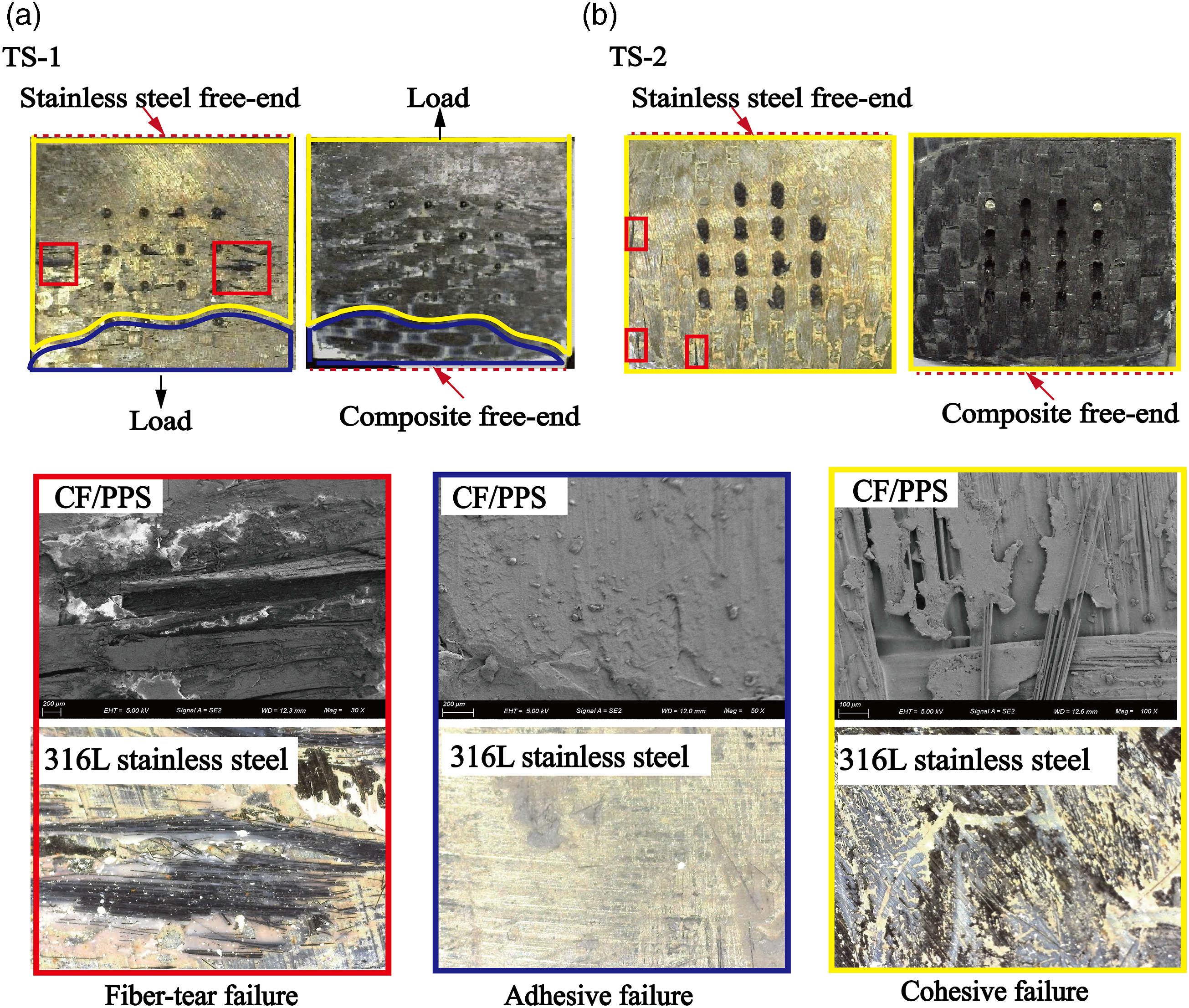
The failure surfaces at both the pin region and the damage initiation region on the metal side are depicted in Figure 16. From Figure 16(a), it can be observed that a considerable amount of PPS resin remained on the pin’s surface, these findings can further prove the adhesive bonding between the pin and CF/PPS in the welding process. Based on the results in the Figure 16(b), it can be seen that the failure surface of the metal substrate in the TS-2 joint retains more resin near the damage initiation region compared to the TS-1 joint, which will enhance the first debonding strength of the TS-2 joint. For R joints (without pins), it can be seen from the figure that there is almost no PPS resin on the metal substrate in the damage initiation region, it indicates that there is no bonding between the metal substrate and CF/PPS in these areas, which will influence the mechanical properties of the welded joint. The failure surfaces at both the pin region and the damage initiation region on the metal side.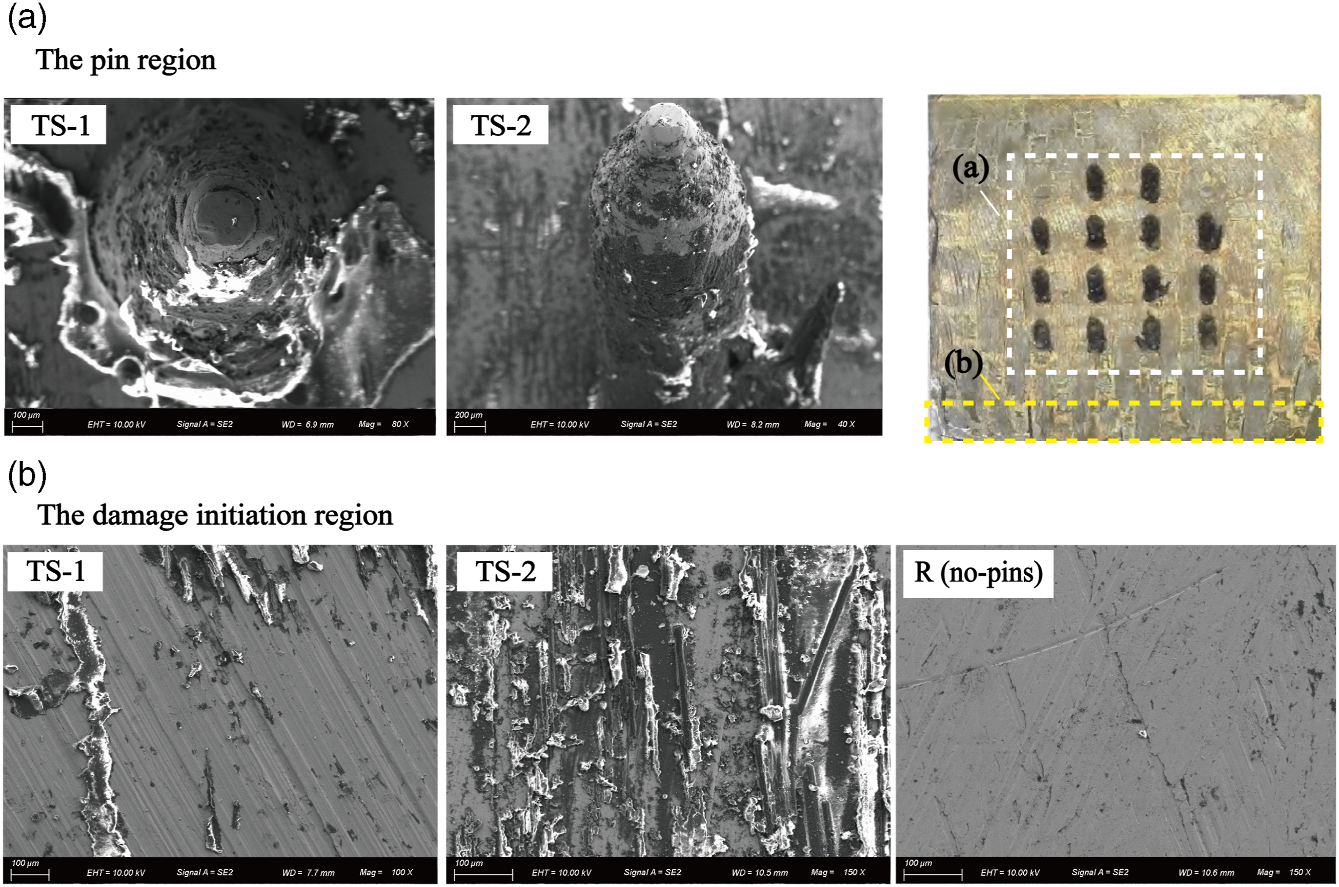
To further investigate the effect of temperature distribution on the failure mode of the welding surface, numerical simulations were carried out to analyze the temperature distribution in the welding zone after applying a consolidating force F
w
to the joint for 15 s, as shown in Figure 17. Based on the simulation results, the welding zone is categorized into the melted zone (surface temperature higher than 280
o
C and unmelted zone (surface temperature less than 280
o
C). Notably, the shape of the melted area in the numerical simulation results is similar to actual melted area (Figure 15), which confirms the accuracy of the proposed numerical model. From Figure 17(a), the PPS matrix in the edge of the welding zone did not reach the melting temperature, due to the shorter induction welding time of the TS-1 joint (12 min) compared to the TS-2 joint (27 min). Consequently, adhesive failure was prone to occur in these regions, which can result in reduced welding strength. Conversely, for the TS-2 joint (Figure 17(b), the larger melted area on the composite material surface improved the welding quality of the joint, which can lead to the cohesive and fiber-tear failure as the primary failure mode on the welding surface after joint failed. Therefore, it can be concluded that the temperature distribution in the weld zone plays a key role in the failure mode of the welding surfaces. Although higher micro-pins increase the induction welding time of the welded joints, the total heat input at the welding interface is enhanced, which can result in an enlarged melted area in the welding zone. Numerical simulation results of the temperature distribution in the welding zone.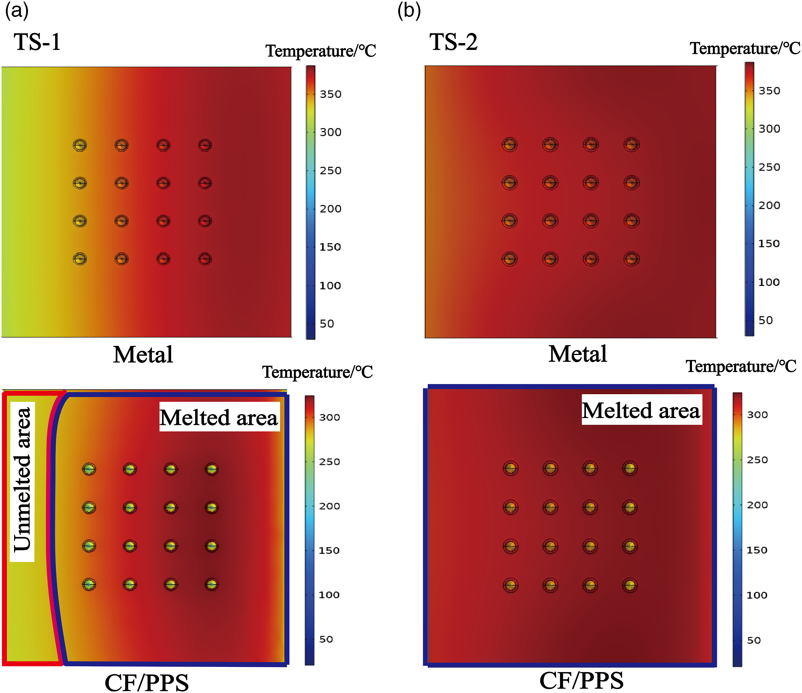
Effect of pin numbers on joint performance
Forming quality of welded joints
The installation quality of the joint for different pin numbers is depicted in Figure 18. It can be observed that the TS-3 joint exhibits slight delamination damage and interface voids in the composite material, which will potentially enhance the mechanical properties of the CF/PPS after joint formation. The resin-rich region is also reduced compared to the TS-2 joint, which can improve the welding quality between the composite material and the micro-pin to some extent. Additionally, the shorter induction welding time in the TS-3 joint (20 min) reduces the heat transfer to the composite material during pin insertion, which can decrease the heat input at the welding interface and reduce the possibility of damage to the composite material. Influence of different pin numbers on joint installation quality (a) TS-2, (b) TS-3.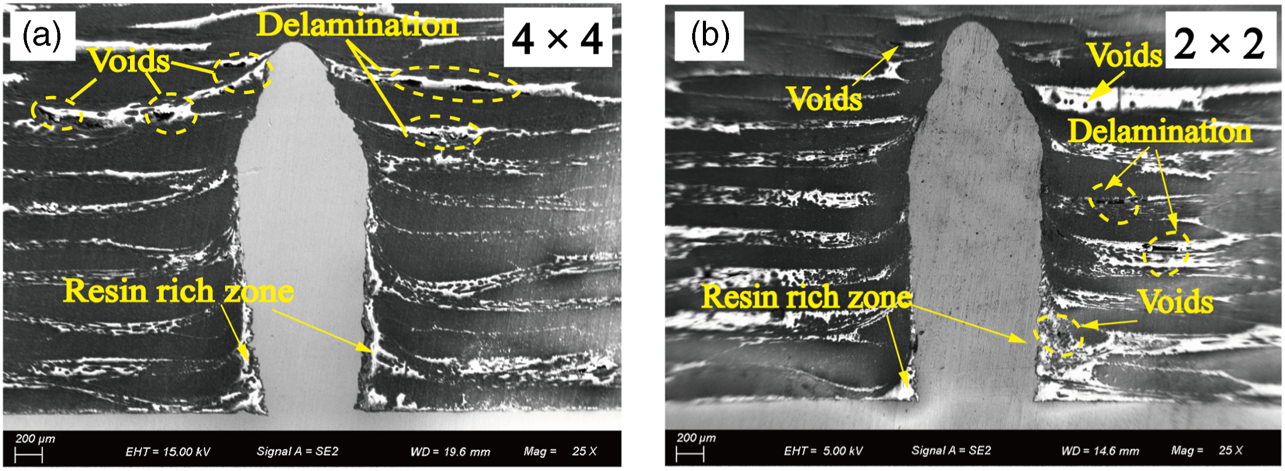
Failure processes and modes of CF/PPS-metal pinned joint
The variation of L-D and R-D curves for welded joints are shown in Figure 19(a). From the L-D curves, it can be seen that the TS-3 joint suddenly failed at D = 0.52 mm, and the ultimate load and energy absorption of the TS-3 joint decrease by 7.71% and 631.7% respectively, compared to the TS-2 joint. Furthermore, as shown in the R-D curves in Figure 19, the slope of the R-D curve of TS-3 is significantly higher than that of TS-2 at the beginning of loading, the rapid increase in rotation angle of the TS-3 joint is attributed to the reduction in the number of pins, which reduces the joint’s resistance to peel deformation during the initial tensile stage. The rotation angle of the TS-3 joint gradually decreased with increasing tensile displacement, reaching its peak value (2.1°) at D = 0.35 mm. Subsequently, it significantly decreased at D = 0.52 mm. In contrast, the rotation angle of the TS-2 joint continued to increase even after reaching the peak load (D = 1.12 mm). Considering the simulation results shown in Figure 12, it can be inferred that this is due to the slow pull-out of pins within the TS-2 joint after interfacial debonding from the CF/PPS material. This further increases the opening distance between the materials, leading to a continued increase in the rotation angle of the joint. Joint deformation, strains and damage mechanisms for different pin numbers.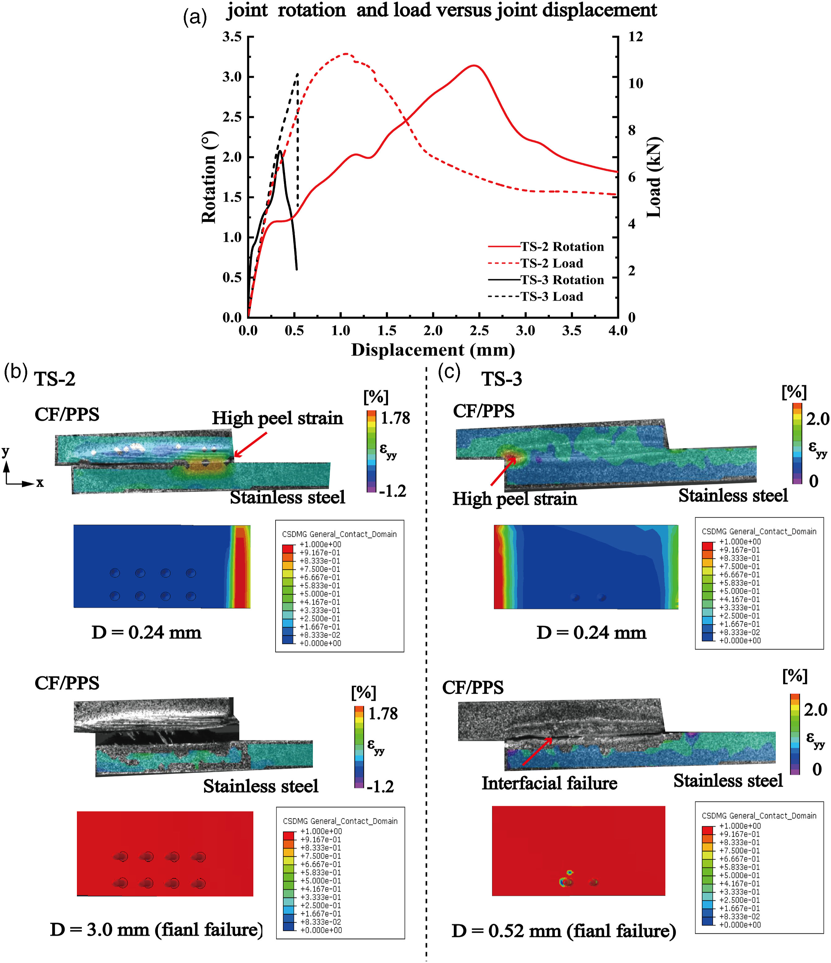
The transverse normal DIC strain of TS-2 and TS-3 is shown in Figure 19(b)–(c). Compared to the TS-2 joint, high peel strain in the TS-3 joint initially occurred at the free end of the metal. The peel strain then propagated from both sides towards the center until the TS-3 joint failed. Comparing the final failure form of the TS-2 joint (D = 3.0 mm) with that of the TS-3 joint (D = 0.52 mm), it can be observed that the opening distance of the weld joint in the TS-3 joint is significantly lower than that of the TS-2 joint. Considering that both types of joints have the same pin height, it indicates that the pins within the TS-3 joint did not completely pull out during the tensile process, which will further affects the growth of the joint’s rotation angle.
The failure mode of the welded joint is depicted in Figure 20. As shown in the figure, micro-pins in the TS-2 joint underwent a bending deformation of 35.7° during the joint failure process and then were completely pulled out. In contrast, micro-pins in the TS-3 joint experienced smaller bending deformation angle of 17.4°, which resulted in partial pin pull-out after the tensile test. These different failure modes can be attributed to variations in joint installation quality. Based on the results from Figure 18, as the number of pins increased, the welding quality of the joint decreased because more damage occurred at the welding interface between the pin and the CF/PPS material, which made micro-pins more susceptible to sliding out along the hole wall during the tensile process. Conversely, although the TS-3 joint shows better joining quality, the lower number of micro-pins result in reduced load transfer during the joint failure process. Based on the above findings, it can be concluded that a higher density of micro-pins increases the resistance to joint peel deformation in the through-thickness direction, and facilitates absorbing more energy during the tensile process, which will prevent significant variations in the joint rotation angle and ultimately improve the bearing performance of the welded joint. The failure mode of the SLJs (a) TS-2, (b) TS-3.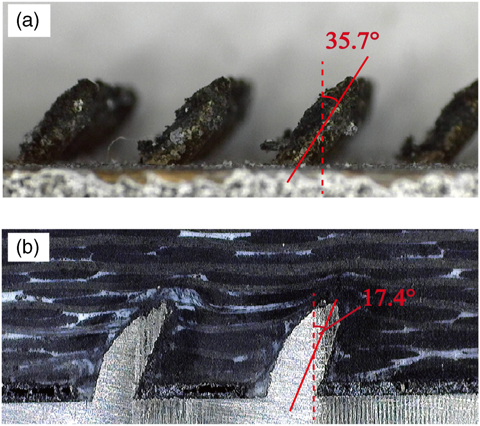
Conclusions
In this paper, the formation and failure mechanisms of CF/PPS-metal induction welding joints strengthened by SLM pins were investigated by combining the experimental tests and numerical simulation approaches. The effects of geometrical parameters of micro-pins on the forming and load-bearing performance of the joints were analyzed. Two simulation models were developed to simulate the heat transfer during the induction welding process and the tensile failure process of the joint. Based on the experimental and simulation results, the following conclusions can be drawn: (1) The proposed model can effectively predict the temperature distribution during induction heating transfer and the process of tensile failure of the joint, it will be helpful to reveal the formation and failure mechanism of the hybrid joint. (2) The bridging force between the pin and the composite laminate not only allows the pin to transfer the load together with the welding surface during the tensile process, but also inhibit the welded joint from peeling failure. Therefore, compared with welded joints without micro-pins, the bearing performance of induction welding joints reinforced with pins is significantly improved. The first debonding strength, ultimate strength and energy absorption capacity of the welded joint are increased by up to 117%, 159% and 1758%, respectively. (3) Higher pins can absorb more energy through significant bending deformation, consequently slowing down the failure process of the welded joint. As a result, the failure displacement of the welded joint exhibits an increase of 481.8% when the pin height increases from 1 mm to 3 mm. However, it should be noted that increasing the pin height also impacts the maximum temperature and area of the heat-affected zone (HAZ) in the CF/PPS, which can lead to greater damage such as voids and delamination in the composite material. Conversely, reducing the number of pins will result in higher peel strains at the overlap edges during the tensile process, which can in turn increase the joint rotation angle and eventually cause sudden failure of the welded joint. (4) Increasing the height of the pin will reduce the heat input per unit time at the welding interface. As a result, a longer induction heating time is required to promote the formation of the welding zone. When the temperature is uniformly distributed in the welding zone, the failure mode of the welding surface exhibits high-energy fiber-tear failure and cohesive failure. However, when the temperature distribution in the welding zone is not uniform, the welding surface will experience a mixed failure mode (fiber-tear failure, cohesive failure, and adhesive failure) after tensile test.
Footnotes
Author contributions
The authors confirm contribution to the paper as follows: Conceptualization, Methodology, Software, Investigation, Formal Analysis, Writing-original draft: Xuda Qin; Formal Analysis, Software, Data curation, Writing-original draft: Tian Yu; Software, Validation, Visualization, Writing-review and editing: Shipeng Li; Software, validation: Guoyu Fu; Resources, Supervision: Xianming Meng; Conceptualization, Funding acquisition, Resources, Supervision, Writing - review and editing: Hao Li (Corresponding Author). All authors reviewed the results and approved the final version of the manuscript.
Declaration of conflicting interests
The author(s) declared no potential conflicts of interest with respect to the research, authorship, and/or publication of this article.
Funding
The author(s) disclosed receipt of the following financial support for the research, authorship, and/or publication of this article: This work was supported by National Key Research and Development Program of China (grant number: 2019YFE0124100) and National Natural Science Foundation of China (grant numbers: 52075380 and 52275459).