
Abstract
Hybridizing different materials, such as metals and polymer matrix composites, has recently drawn attention as it can produce a unique material that offers advantages from both the metals and the composites. However, the strict surface preparation required, a relatively low production rate, and the resultant weak interface have been the hurdles for this technology. The low surface energy of some polymeric materials, such as polypropylene (PP) and their composites, has posed even more challenges when bonding with metals. This work aims to develop a hybridized PP matrix composite and aluminum with through thickness reinforcements (TTRs) at a high production rate and with minimal treatment. Long glass fiber PP matrix composite (LFT glass/PP) is integrated with aluminum sheet using an extrusion–compression molding process at a rate of 2 minutes per plate. The bonding between these two materials is achieved using the TTRs on the aluminum sheet that provide mechanical locking at the interface. The hybridized aluminum and glass/PP LFT material is evaluated on its performance in lap shear, short beam shear, flexure, and tension. It is concluded that the mechanical locking at the interface provides a lap shear bonding strength of 6.8 MPa, and the hybridized material has significantly improved tensile and flexural modulus as well as strength compared to the glass/PP LFT only. The same approach can be readily extended to hybridizing other polymer matrix composites with metallic materials.
Introduction
A hybridized material is an immiscible mixture comprised of two or more types of materials. A typical hybrid material such as fiber metal laminate 1 –3 consists of a metal and a polymer matrix composite. Metals have high bearing strength, impact resistance, and are easy to repair. Polymer matrix composites have excellent fatigue characteristics and high specific strength and specific stiffness. The hybridization of these two materials results in superior fracture and fatigue resistance, excellent impact properties, high damage tolerance, and good environmental resistance. The metal/polymer matrix composite hybrid materials currently have practical applications in the aerospace, 1 –3 medical, 4 and automotive 5 –7 industries as well as the military. 8,9
Aluminum alloy is a common metallic material that is used to hybridize with other materials such as glass fiber epoxy composite, 1 glass fiber nylon composite, 9 and glass fiber polypropylene (PP) composite. 2 Typical examples of the application of aluminum/composite materials include the fuselage and leading edges in Airbus 380 as reported by Vlot and Gunnink 10 and bulk cargo bay floor in Boeing 777 as reported by Evancho. 11 Extensive research related to the characterization and manufacturability of composite/metal hybrids has shown the advantages of the hybrid materials over conventional aluminum. Krishnakumar showed that many fiber metal laminates had considerably higher tensile strength than that of aluminum alloys. 12 Khalili et al. observed that the addition of metal layers in glass fiber-reinforced polymer composite improves its tensile, bending, and impact properties. 13 Vogelesang and Vlot conducted tension–tension fatigue tests on glass laminate aluminum-reinforced epoxy and monolithic aluminum alloy. The tests showed that crack growth rate in fiber metal laminate was one-tenth to one-hundredth of those measured in aluminum because of the crack-bridging effect of fibers. 14 Aluminum was integrated with glass fiber nylon matrix composite using extrusion–compression molding (ECM), and the hybrid tailcone was able to withstand the high temperature and pressure from firing. 9,15 Due to the different characteristics of the metal and the composite material, weak bonding is normally resulted between the metal and the composite material. The mechanical properties of these metal/polymer matrix composite hybrid materials are highly dependent on the bonding between the metal and the composites. High bonding strength at the metal/composite interface normally results in hybrid materials with excellent mechanical properties. Research has been conducted to improve wetting of the metal by the polymer to increase the bonding strength between the metal and the composite. Different surface treatment methods, such as milling, grit blasting or sanding on the metal surface, 15 –17 or anodizing the aluminum with phosphoric or chromic acid to provide a thick, porous, strongly adhering oxide layer, 18 –21 have been developed. These surface treatments are carried out to increase surface roughness as they are an excellent source of mechanical interlocking between metal and polymer which greatly increases bond strength. A layer of primer or adhesive may also be applied to the metal surface to further improve bonding. 7,22 A group of researchers have used vapor grown carbon fiber interleaves to improve the interface fracture toughness for aluminum/glass fiber-reinforced composite laminates. 23 These treatments on the aluminum surface have resulted in good bonding with composite materials. However, the treatments are time-consuming and involve corrosive and dangerous chemicals, both of which pose challenges for practical applications.
In addition to the surface treatment on the metal, work has previously been done on plasma treating the PP surface to enhance bonding strength. Polyolefin such as PP has low surface energy that results in weak bonding with aluminum. 24,25 PP has a surface energy of 27 mN/m, 26 that is slightly higher than that of Teflon (15 mN/m), 27 a material that is well known for its non-stick characteristic. The bonding between aluminum and PP or its matrix composite has been reported to be minimal without any treatment. 28 Gallant and Véronique 28 have performed an adhesion study between aluminum and PP by plasma treating the surface. Plasma treatment was applied on the surface of the PP, and aluminum plate is degreased, abraded, and primed before different adhesives, such as epoxy, urethane, and methacrylate, were used to bond the aluminum and the PP. There were totally 10 epoxies, 4 urethanes, and 11 methacrylate used for bonding the aluminum and the treated PP. Lap shear testing was performed to compare the bonding strength of these 25 adhesives. It was reported that the shear strength ranged from 1.6 MPa to 7.4 MPa, most of which has a shear strength less than 5 MPa. 28 After using a multiple-step treatment, including acetone rinse with oven dry, plasma treatment, methanol rinse and with oven dry, the shear strength in one of the bonding scenarios reached 11 MPa while the bonding strengths for the other cases ranged from 4.7 MPa to 9.4 MPa with large standard deviations.
Z-pinning is another method to increase delamination strength. It is a typical form of through thickness reinforcements (TTRs) and it has been used to increase the delamination strength of composite laminate. Developed in 1990, it is an ultrasonically assisted Z-fiber technique used to add reinforcements in the through thickness direction. 29 High strength carbon steel, silicon carbide, aluminum, stainless steel, titanium, and so on are materials commonly used for Z-pins. Various studies have been performed to indicate the effectiveness of Z-pins on limiting delamination. Yan et al. 30 and Cartie and Partridge 31 have observed experimentally and numerically the improvement in lap shear strength of Z-pinned laminates. The low-velocity impact resistance of the Z-pin-reinforced composite was studied by Palazotto et al., 32 and the results showed the improvement in mechanical properties of the structure. The strain energy release rate of delamination crack is reduced because of the Z-pins load bearing capability, which increases the interlaminar strength of the composite. Löbel et al. 33 compared the tensile strength of composite materials with adhesively bonding and Z-pinning. It was found that the composite material with Z-pinning had higher joint efficiency and higher tensile strength than the composite material with adhesive bonding because the Z-pinning enhanced the damage tolerance at the bond by bridging cracks and suppressing peel stress. 33 Aktaş and Polat 34 studied the effect of the addition of Z-pinning to adhesively bonded composite. It was found that the tensile shear lap joint strength was significantly improved with the Z-pinning being added, and the sample with the pinning showed progressive failure in contrast to the catastrophic failure exhibited in the sample with adhesive-only bonding. 34 However, there have been minimal studies on using Z-pinning for hybridizing metal and composite materials such as aluminum and long glass fiber-reinforced PP. In fact, it has been indicated that Z-pinning is not suitable for fiber metal laminate hybrid materials. 23
In this work, aluminum sheet with TTRs was used to hybrid with LFT glass fiber-reinforced PP composite. The TTRs were used to improve the bonding between the composite and the metal. The ECM process was used to manufacture the hybrid material. Various tests, such as lap shear, short beam, tensile, and flexural, were conducted to characterize the performance of the LFT/Al hybrid material.
Materials and processing
Aluminum with TTRs was provided by GripMetal™ (Grip Metal, Inc.) as shown in Figure 1. The aluminum sheet has an average thickness of 1.5 mm, the average TTR height is 1.5 mm, and its density is 17 TTRs per square centimeter area. Long glass fiber-reinforced polypropylene (glass/PP LFT) composite with 12-mm long glass fiber and a weight percentage of 30 wt% (Celanese Corporation) was used for bonding the aluminum sheet with the TTRs to form the hybrid material.
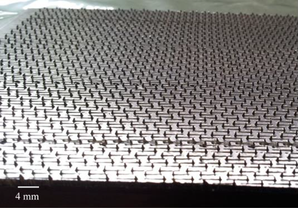
Aluminum sheet with TTRs supplied from GripMetal™.
ECM was used for manufacturing the hybrid material sample. That involves melting the glass/PP LFT pellets in a low shear extruder and compression molding the extrudite using a hydraulic press. ECM is a high production rate process that provides reduced fiber attrition and therefore good mechanical properties. Figure 2 shows the schematic of ECM used to process the metal/composite hybrid material. Glass/PP LFT pellets were fed into the extruder barrel through a hopper and melted while the screw transports the pellets to the front of the barrel. The extruder has a temperature of 175°C which ensures melting of the PP matrix while avoiding degradation. A viscous molten extrudite was pushed out by the reciprocating screw before being placed into a 154 × 154 mm2 mold. An aluminum sheet was placed into a 154 × 154 mm2 mold with the side of the TTRs facing up (Figure 2(b)) after being rinsed in acetone. The extrudite was then placed on top of the aluminum sheet. A force of 50 ton (pressure 19 MPa) was applied to ensure the flow and filling of the LFT glass/PP in the mold. The processing time for manufacturing one hybrid material plate was approximately 2 minutes, including placement of the aluminum sheet, extrusion and placement of the charge, compression molding, and demolding. Figure 2(c) shows the LFT on top of the aluminum plate that has filled the mold. An aluminum sheet without any TTRs was molded with the glass/PP LFT composite using the same processing conditions for comparison purposes. In this instance it was noticed that the aluminum without any TTRs and the glass/PP LFT plate separated during demolding and no bonding was achieved at all.
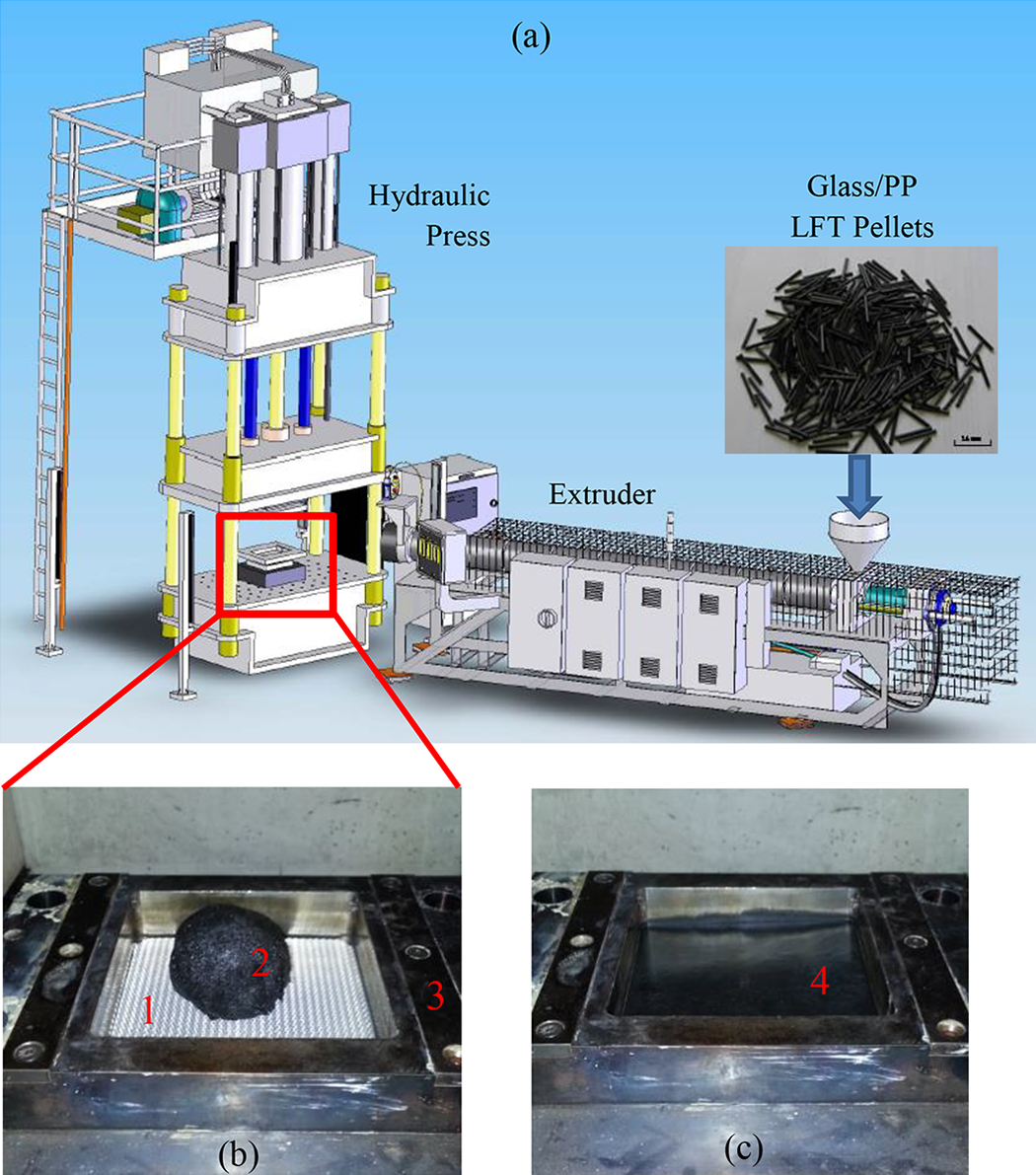
(a) Extrusion–compression molding process used to produce the LFT/Al hybrid material, (b) an aluminum sheet with TTRs in the steel mold and the placement of the LFT glass/PP extrudite on top of the aluminum sheet (1—aluminum sheet with TTRs, 2—LFT glass/PP extrudite; 3—6 × 6 in.2 steel mold), and (c) the hybrid LFT/Al plate in the mold (4—hybrid LFT/Al plate).
Figure 3 shows a hybrid plate and the cross section of the LFT/Al panel. The cross section of the hybrid sample was polished and examined under optical microscope. It was noted under optical microscopic imaging that there was adequate bonding at the LFT/Al interface (Figure 3(c)). The coupon strip specimen in Figure 3(b) and (c) that was prepared from the plate shows a series of TTRs. Its cross section was also examined under scanning electron microscopy (SEM). SEM micrographs in Figure 4 verify the good bonding between the glass/PP LFT and the aluminum TTRs. The micrographs show the glass fiber in the LFT also has relatively uniform distribution, and there are glass fibers present at the corners of the TTRs, indicating adequate flow during the ECM processing.
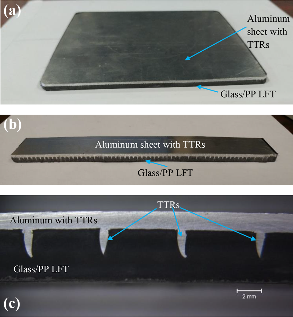
(a) The hybridized LFT/Al plate (6 × 6 in.2) after being demolded from Figure 2(c), (b) a coupon strip specimen cut from the plate showing a series of TTRs at the interface, and (c) a close view of the TTRs interlocking with the glass/PP LFT composite.
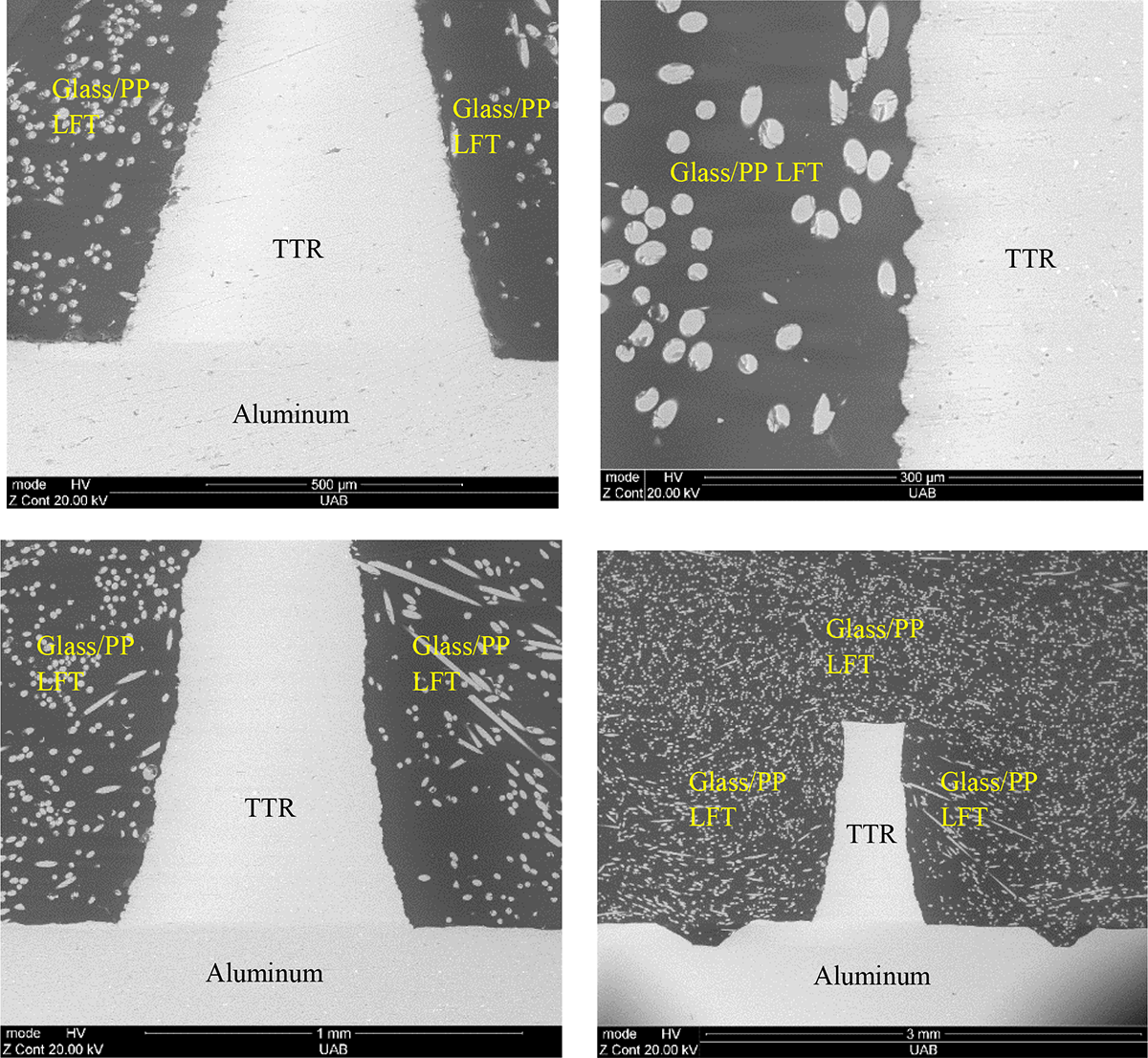
SEM images at the metal/composite interface showing the good consolidation of the glass/PP LFT and the adequate bonding between the aluminum TTR and the LFT composite.
The molded plates were then cut into respective specimen sizes for lap shear, short beam bending, flexural, and tension testing. Plates made of 30% glass/PP only were molded using the same processing conditions and tested for comparison purposes.
Results and discussion
Lap shear test
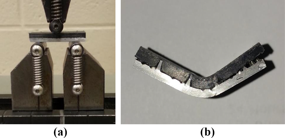
Lap shear testing was conducted according to ASTM D3164—Standard Test Method for Strength Properties of Adhesively Bonded Plastic Lap-Shear Sandwich Joints in Shear by Tension Loading. The test was carried out to evaluate the bonding strength between the aluminum and the glass/PP LFT composite using tension load and study its debonding mechanism. Figure 5(a) shows a sample prepared for the lap shear testing with a slot cut on both the aluminum and the composite sides. The lap shear testing setup in Figure 5(b) shows the sample being clamped at both ends and loaded in tension. Figure 5(c) and (d) shows the separation between the TTRs and the LFT after the completion of the test. The load versus displacement curves for the lap shear samples are shown in Figure 6. The specimen fails at around 2500 N force as indicated in the load–displacement curve in the figure. Initial elastic deformation was noticed at the beginning of the test as the curve is linear and the materials behave elastically. Nonlinear behavior was observed on the hybrid material when the load approaches the peak load. The nonlinear region is probably caused by the nonlinearity of glass/PP LFT that is seen from the tensile testing of the glass/PP LFT material and/or the nonlinearity of the aluminum TTR after it reaches yield point. After the peak load was reached, there was a separation between the TTRs and the LFT, and the load dropped gradually because of the pullout of the TTRs from the glass/PP LFT composite that was observed during the test. The friction force between the TTRs and the glass/PP LFT composite during the pullout resulted in gradual load drop instead of sudden failure. The pullout of the TTRs from the glass/PP composite after the peak load provided extra energy absorption mechanism after peak load was reached. Eventually, the LFT and the TTRs separated completely and there was a sudden load drop finally to nearly 0 N. From the load–displacement curve, there was no sudden load drop at the peak load as is normally seen in adhesively bonded specimens. 2,34,35 The SEM micrographs in Figure 7 showed the inclined TTRs from original upward orientation due to the pullout. The angle was measured to be approximately 12°. There is no noticeable fracture at the high stress area of the corner of the TTRs because of the high plasticity of the aluminum.
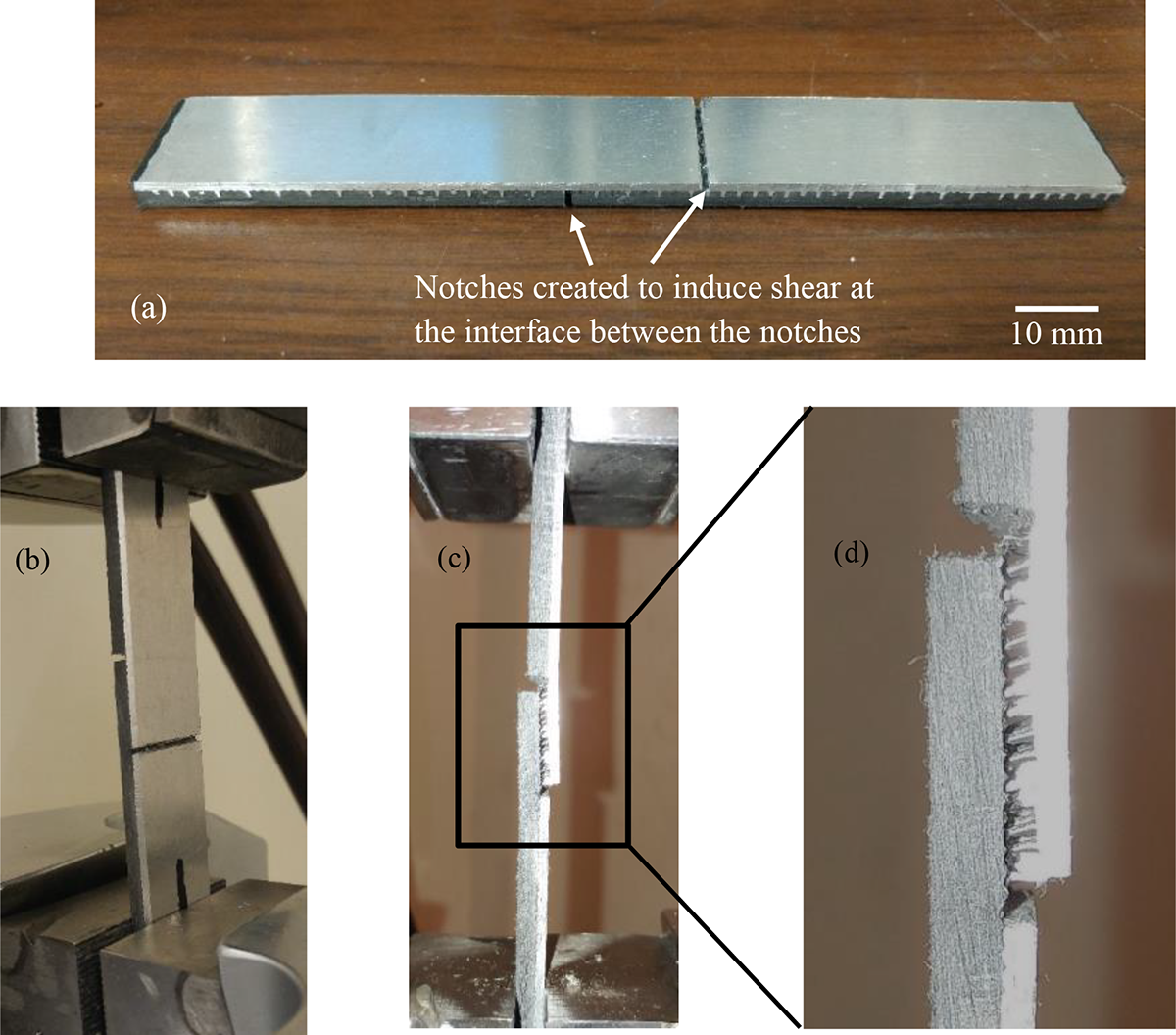
(a) A lap shear sample with two notches scored to induce shear at the interface between the notches, (b) the lap shear testing setup showing the sample being clamped at both ends and loaded in tension, (c) and (d) the tested specimen showing the separation between the TTRs and the LFT.
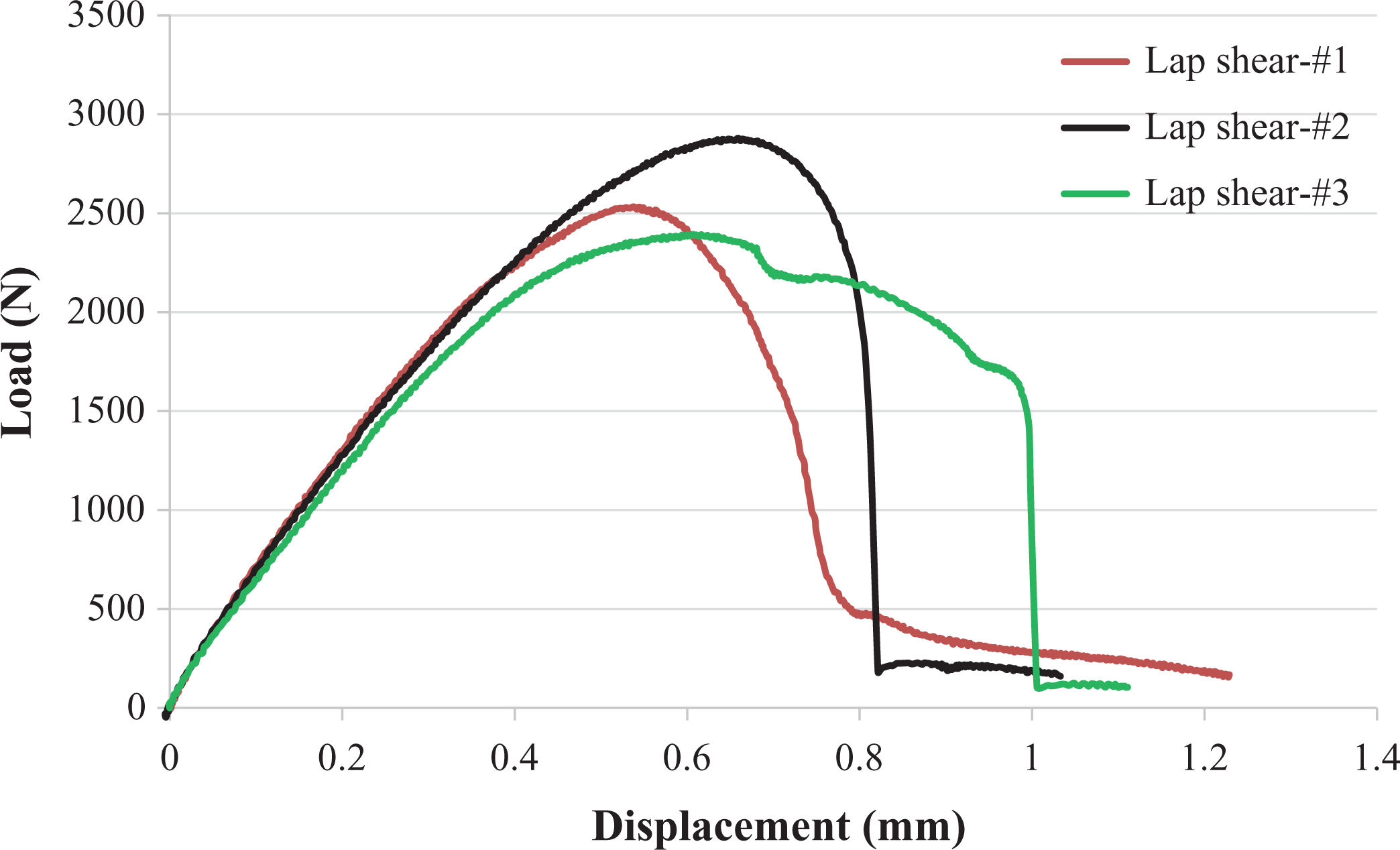
Load versus displacement curves of the lap shear tests for the LFT/Al hybrid material. The pullout of the TTRs from the glass/PP composite avoids sudden load drop after peak load is reached.
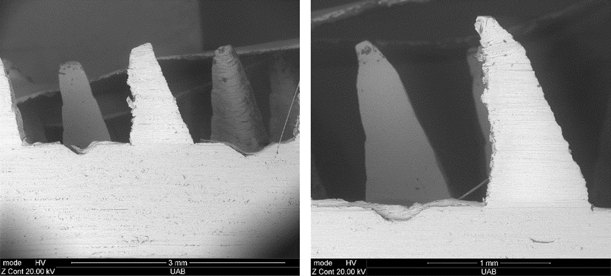
The inclined TTRs due to pullout mechanism during lap shear testing.
The lap shear strength is calculated to be peak load over area. Table 1 lists the lap shear strength of the hybrid material. An average shear strength of 6.8 MPa is obtained for the LFT/Al specimens bonded by the TTRs. This lap shear strength is compared to the previouly published strength values that were obtained using the adhesive bonding method. Lap shear testing conducted by Guruşçu 2 showed that the PP-based film containg 20 wt% maleic anhydride modified PP (PP-g-MA) had a shear strength of 5.93 MPa. The sample with silane-treated aluminum had an average shear strength of 2.03 MPa.
Lap shear strength of the LFT/Al hybrid material.
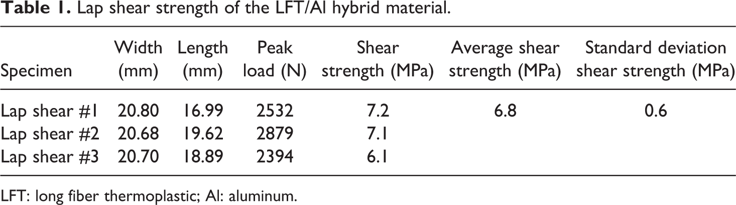
LFT: long fiber thermoplastic; Al: aluminum.
Short beam shear test
Short beam shear test is another test commonly used to evaluate bonding strength. ASTM D2344—Standard Test Method for Short Beam Strength of Polymer Matrix Composite Materials and Their Laminates—is the standard for this test. Short beam specimens have a span length four times that of its thickness. The small span length results in shear stress through the specimen thickness with the center experiencing maximum shear stress. Short beam samples with a thickness of 3.8 mm and width of 15.5 were prepared and tested. Figure 8(a) shows the setup of the short beam test. The tested sample in Figure 8(b) shows delamination at the interface. The maximum load was averaged to be approximately 2500 N. Short beam strength is calculated based on the following equation specified in the ASTM standard

where Pm is the maximum load observed during the test, b is the specimen width, and h is the specimen thickness.
(a) Short beam testing and (b) a tested specimen showing delamination.
The specimen shows averaged short-beam shear strength of 32 MPa. The shear failure occurred to the aluminum sheet and the LFT as shown in Figure 8. The separation between the aluminum sheet and the LFT is noticed. There is also separation between the TTRs and the LFT.
Flexural test
Flexural test was conducted according to ASTM D790—Standard Test Methods for Flexural Properties of Unreinforced and Reinforced Plastics and Electrical Insulating Materials. Flexural sample size has a width of 20 mm and thickness of 3.8 mm. The flexural strength equation is

where F is the load, L is the support span, b is the specimen width, and d is the specimen thickness. The properties of LFT/Al hybrid composites mainly depend on the interfacial bonding between the metal and fiber composite. Strong bonding helps to transfer load from fiber composite to metal and vice versa. The testing setup is shown in Figure 9, and the typical flexural stress–strain curve for the hybrid material is shown in Figure 10. A typical stress–strain curve of glass/PP LFT sample is also shown in the figure for comparison purpose. It can be seen that the hybrid material has much higher strength than the LFT sample. The LFT sample showed sudden load drop after it reached the peak load, while the hybrid sample showed gradual load decrease after reaching peak load.
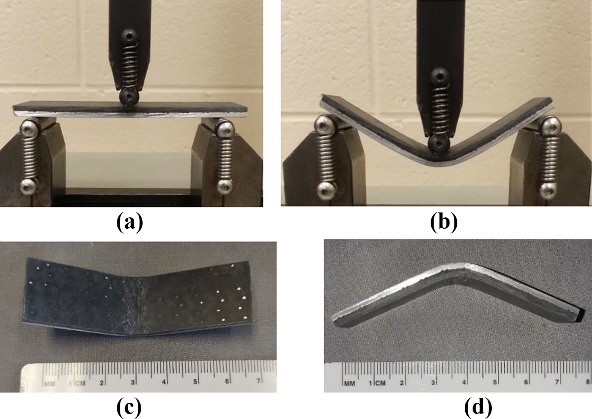
(a) Flexural testing of the hybrid material, (b) large deflection of the hybrid material, (c) and (d) tested flexural specimen showing compressive failure and no noticeable debonding at the interface.
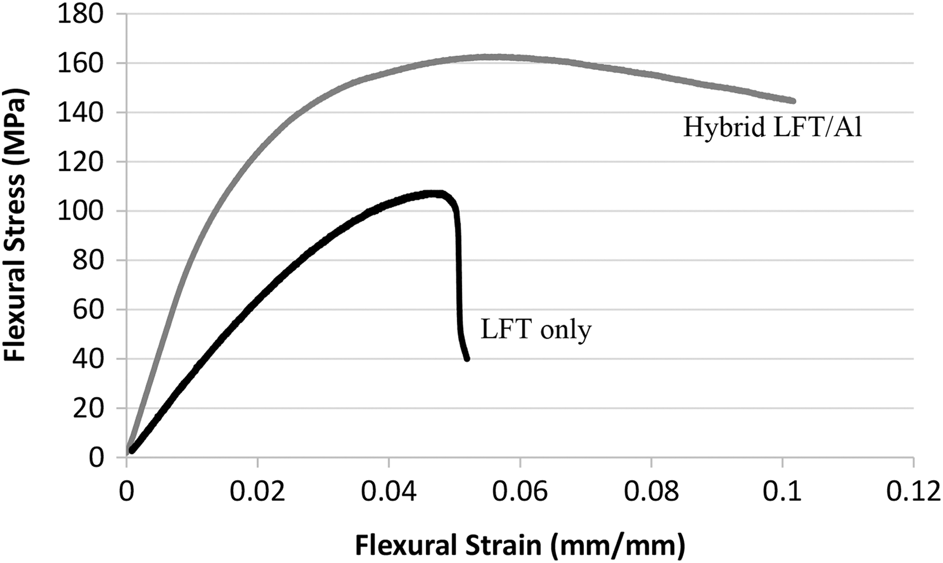
Representative flexural stress and strain curve for the hybrid Al/LFT and the glass/PP LFT only.
Figure 11 compares the flexural strength and modulus of the glass/PP LFT and the hybrid LFT/Al, respectively. The flexural strength of hybrid material is approximately 160 MPa, which is 60% more than that of the LFT. This is attibuted to the addition of the aluminum material, which has higher strength. The tested specimens did not show any tensile failure on the aluminum or failure/debonding at the interface. Only compression failure was observed on the tested specimens at the loading area of the glass/PP composite (Figure 9). The flexural strength of the hybrid material, 160 MPa, is lower than the flexural strength of the fiber metal laminate comprised of aluminum and continuous glass fiber composites 36,37 but similar to the flexural strength of the fiber metal laminate comprised of aluminum and self-reinforced PP composite. 38 The gain of flexural modulus by adding aluminum to LFT is more than doubled. It increased from 3.3 GPa (30 wt% glass/PP LFT only) to 7.5 GPa (LFT/Al hybrid material).
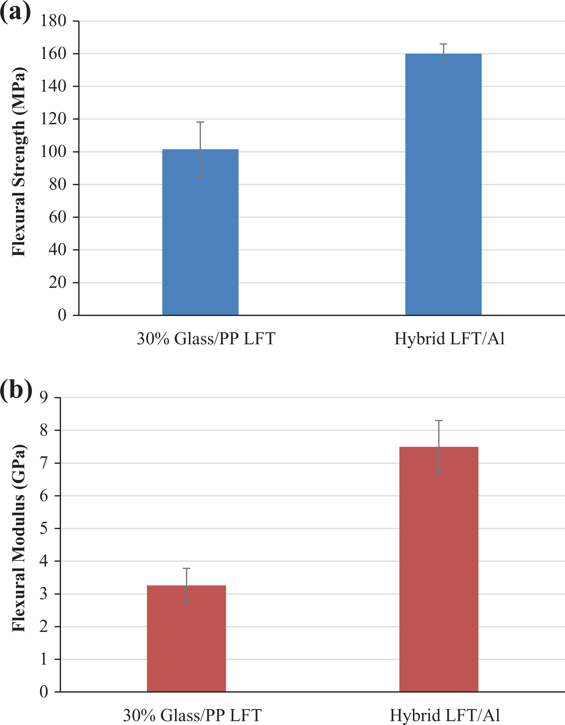
Comparison of (a) the flexural strength and (b) the flexural modulus of the glass/PP LFT and the hybrid LFT/Al.
The flexural stress and strain curve in Figure 10 shows that the flexural strain of the hybrid material is at least 10%. It is noted that the testing was stopped because the sample slipped out of the support rolls due to the large deflection. It is expected that the hybrid material sample would bend more and have a strain to failure larger than 10% if the testing had not been stopped. The large strain to failure of the hybrid material would facilitate forming of the hybridized material into complicated shape/geometry.
Tensile testing
Tensile testing specimens of the hybrid LFT/Al material were prepared and tested according to ASTM D3039—Standard Test Method for Tensile Properties of Polymer Matrix Composite Materials. The tensile sample has a width of 20 mm and thickness of 5.6 mm. The surfaces of the tabbed area on the aluminum and the LFT were slightly sanded with sandpaper and cleaned with acetone. The sanding resulted in roughening of the aluminum surface and exposure of the glass fibers of the LFT, both of which significantly contributed to strong bonding. Tabs with a dimension of 20 × 38 mm2 were prepared from a woven glass fiber epoxy composite. Finally, epoxy adhesive was used to bond the tabs to the sample for the tensile testing. Figure 12 shows the load versus displacement curves of the hybrid material. Delamination between the metal and composite happened at the load of 4000 N approximately. It is indicated by the load fluctuation on the load–displacement curve. Delamination was caused by the large difference between tensile modulus of the aluminum (70 GPa) and LFT (4.2 GPa). The composite failure occurred at the stress of 57 MPa and a strain of 0.025 due to its lower strain to failure. After the fracture failure of the composite, all of the load was carried by the aluminum. Figure 13 compares the tensile strength and the tensile modulus of the LFT composite only and the LFT/Al hybrid material. A tested hybrid sample in Figure 14 shows the obvious delamination of the composite from the aluminum. The fracture of the LFT composite occurred when the peak load was reached. Samples showed improvements in tensile properties by addition of the aluminum because of its higher strength, 220 MPa. 39
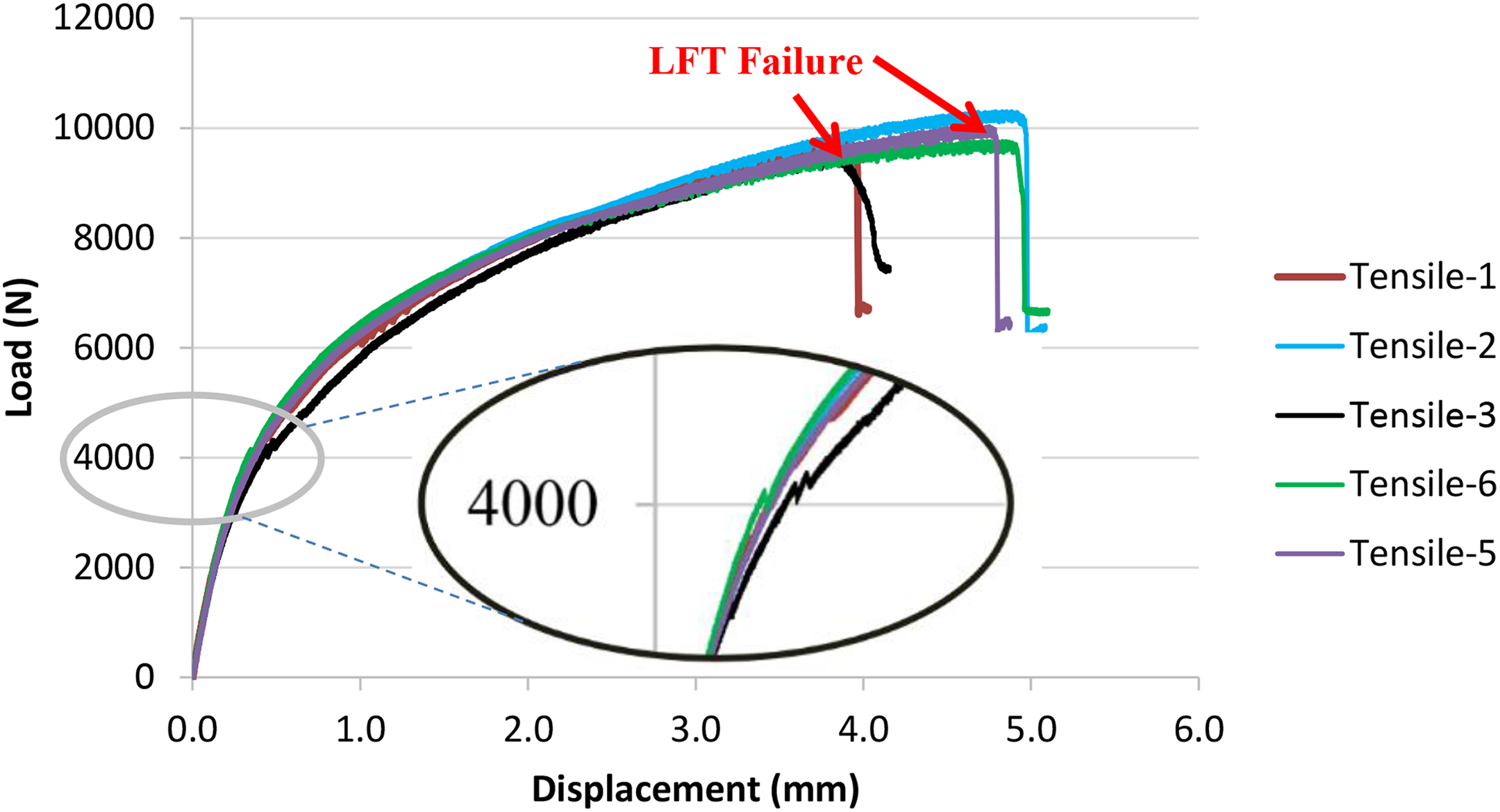
Load versus displacement behavior of the LFT/Al hybrid material.
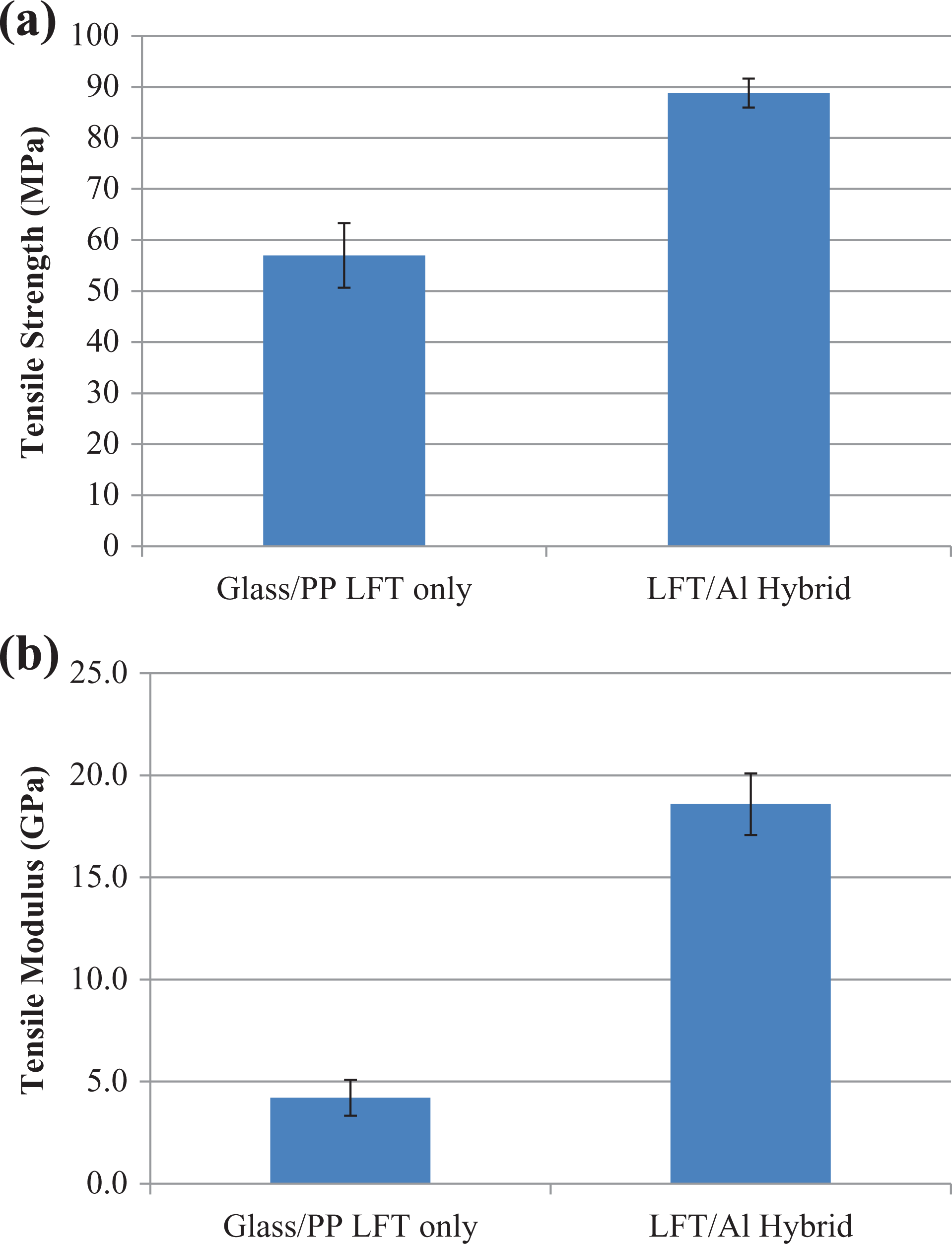
Average tensile strength and modulus of 30% glass/PP LFT and the LFT/Al hybrid material.
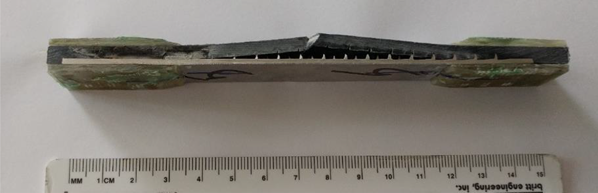
A tested tensile sample showing the delamination and the fracture of the glass/PP LFT composite.
The tension force applied was shared between the composite and the aluminum. The elastic modulus is therefore followed by the rule of mixture,
Conclusions
An aluminum sheet with TTRs was molded with long glass fiber-reinforced PP composite using ECM process at a cycle time of 2 minutes. The microstructural analysis using optical and SEM showed excellent bonding between the aluminum and the LFT composite. The good bonding strength between the aluminum sheet and the long glass fiber-reinforced PP matrix composites was achieved by the mechanical locking at the TTRs and minimal surface treatment on the metal surface or chemical treatment on the polymer was required. The performance of the aluminum/LFT hybrid material in interfacial bonding, flexure, and tension was evaluated. It was found that the lap shear strength was 6.8 MPa which is comparable to the bonding strength achieved using adhesive bonding with surface treatment. Pullout of the TTR results in the gradual load drop peak load instead of catastrophic load drop normally observed from adhesively bonded specimens. The addition of the aluminum significantly increased the flexural and tensile properties of glass/PP LFT. There was no debonding observed at the LFT/Al interface when flexural strain reached more than 10%. Although the manufacturing cost of the aluminum with TTRs could be a hurdle for the use of the hybrid material in certain applications, the excellent bonding at the metal/composite interface through TTRs shows great advantage, such as minimal to no surface preparation, faster processing rate, and superior bonding strength, for other potential engineering applications. The same bonding approach can be extended to any combination of any polymer or polymer matrix composite with metallic materials with TTRs.
Footnotes
Acknowledgements
The donation of the aluminum sheets with integrated hooks from GripMetal™ is greatly acknowledged. The United States government retains and the publisher, by accepting the article for publication, acknowledges that the United States government retains a non-exclusive, paid-up, irrevocable, worldwide license to publish or reproduce the published form of this article, or allow others to do so, for United States government purposes. The department of energy will provide public access to these results of federally sponsored research in accordance with the DOE public access plan (![]() ).
).
Funding
The author(s) disclosed receipt of the following financial support for the research, authorship, and/or publication of this article: This article has been sponsored by UT-BATTELLE, LLC under contract no. De-AC05-00OR22725 with the U.S. Department of Energy.