
Abstract
This work discusses the development and refinement of a polymer/fibre through thickness reinforcement method. Similar in initial concept to the traditional metalworking process of riveting this allows the manufacture of through thickness reinforced 2-D preforms. Pins are placed with deliberate excess length using a veterinary needle to part in-plane fibres. A lay-up with an array of pins is then subjected to a hot-press process flattening the pin ends resulting in a consolidated preform. This preform exhibits useful characteristics such as the ability to be cut and reformed to a new topology, with the through thickness reinforcement also conforming to the new shape. Refinements to the process introduce a multi-stage press process aimed at improving pin orientation with both original and refined processes evaluated using ASTM D5528 to determine the effect on interlaminar fracture toughness.
Introduction
The issue of delamination in composite materials, and the reinforcement through the thickness of materials to resist such damage has been the subject of great study. As well as the well-established methods of Z-pinning [1-3], tufting [4-6], stitching [7-9] and 3-D weaving [10-12] authors have also attempted novel methods of achieving the goals of through thickness reinforcement [13-15].
While each method presents its own unique advantages and disadvantages. It is not uncommon to note a reduction in the in-plane properties. This is most often attributed to; the displacement of in-plane fibres around the Z direction reinforcement known as waviness in the X/Y directions and crimp in the Z direction, the damage of in-plane fibres as a result of the reinforcement process, or simply a reduction in the volume of fibre dedicated towards in-plane performance [16-19].
Materials + methods
Pinning + pressing process
The pinning process uses a commercially available 3-D printing filament manufactured by Markforged. This filament consists of a continuous fibre reinforcement encased in a Nylon matrix. In this study, two materials are evaluated – one containing carbon as the reinforcing fibre and the second containing Kevlar.
The 2-D fibre layups are constructed using a combination of Tenax 5HS-6K-375GSM satin weave carbon fibre with an areal weight of 375 g/m2 referred to as ‘5HS’ and Saertex ST2B Biax N Crimp 0–90 non-crimp fabric consisting of UD layers bound in a 0–90 orientation with an areal weight of 317 g/m2 referred to as ‘NCF’.
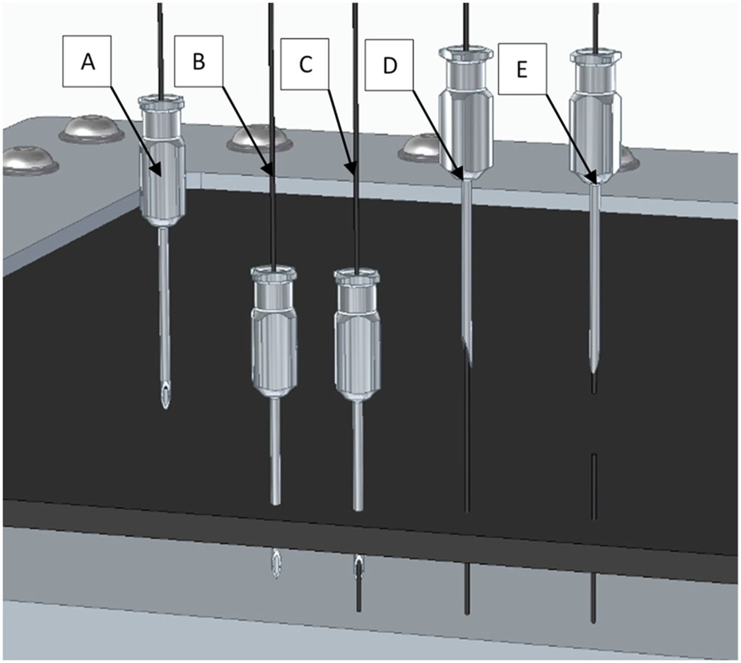
The 2-D lay-up is placed into a metal frame and clamped in place. The pinning process uses an 18 Birmingham Gauge veterinary needle. This needle is used to part the fibres allowing the easy threading of the filament through the needle. This follows a five-step process with the following list corresponding to the steps shown in Figure 1:
The filament is threaded through the needle. The needle is pushed through the fabric. The filament is threaded through the needle until it hits the backstop. The needle is withdrawn while the filament is held in position. The filament is trimmed to the desired height above the surface. Representation of pinning stages.
This process is conducted to place an array of pins. In this study, this is conducted entirely by hand with the use of the 5HS weave pattern as a placement guide for the pins resulting in ∼5 mm pin separation.
Once the desired array of pins has been placed the part may then be subjected to the press process. Initially, this press process utilised a single-stage operation. The resin transfer moulding (RTM) tool is used as a convenient thermal mass heated to 150°C in an oven. The pinned fabric stack is removed from the pinning frame and placed into the tool. The lid of the tool is then bolted into place. During this time, the heat of the tool causes the pins to flatten and deform as shown in Figure 2. The tool is then left to cool to ambient temperature. While it is possible to immediately conduct infusion of the part at this point, in this study, the RTM tool was always opened for inspection of the part prior to infusion.
Illustration of the single-step process.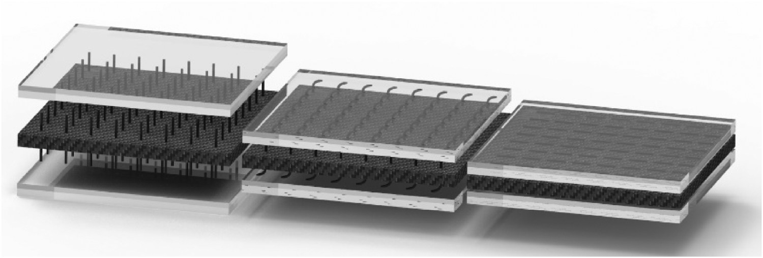
All sample configurations are infused using the RTM process with the resin system comprising of Gurit Prime-27 resin and Prime slow hardener this resin system offers low temperature cure and ease of mixing/infusion.
Preform characteristics
The final result of this process is a consolidated preform with ‘cardboard-like’ qualities. The flattened pins hold the layers together allowing ease of handling. This may be subsequently pressed a second time in a contoured tool with the pins conforming to the new geometry as shown in Figure 3.
Images of re-pressed preform using an omega shaped tool.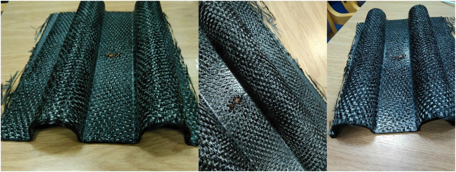
Refinement of methods
The single-stage process presented thus far proved to have issues when evaluated in mode 1 using the ASTM D5528 [21] double cantilever beam test. The initial samples using a 12-layer 5HS lay-up with 0–90 stacking sequence demonstrated a stick-slip propagation and the shallow pin angle resulted in sub-optimal mode 1 performance. In a collaborative work with Edinburgh University [20], samples for lap-shear tests were constructed. The short overlap of the pinned region necessitated a change in the methods used. Instead of removing the part from the clamping frame used to hold the fibres in place during pinning, the part remains clamped and the pin ends are pressed in-situ. This is done with the use of a heated plate placed upon the upper layer of pins. As illustrated in Figure 4, the same backstop (lower plate of image) used during the pinning process to set consistent pass-through length is used to prevent the pins from being pushed through the fibre by the plate.
Stage 1 of refined press process.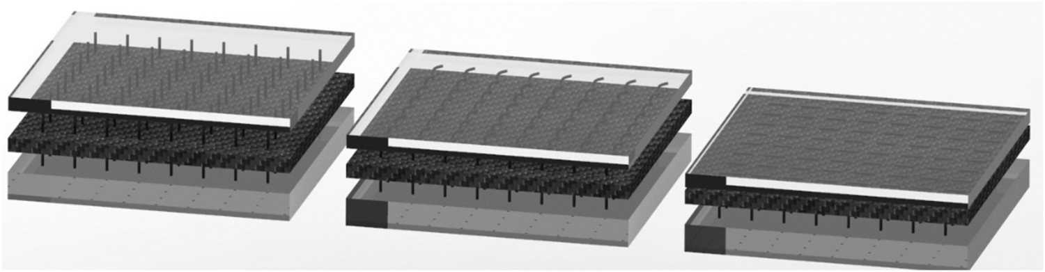
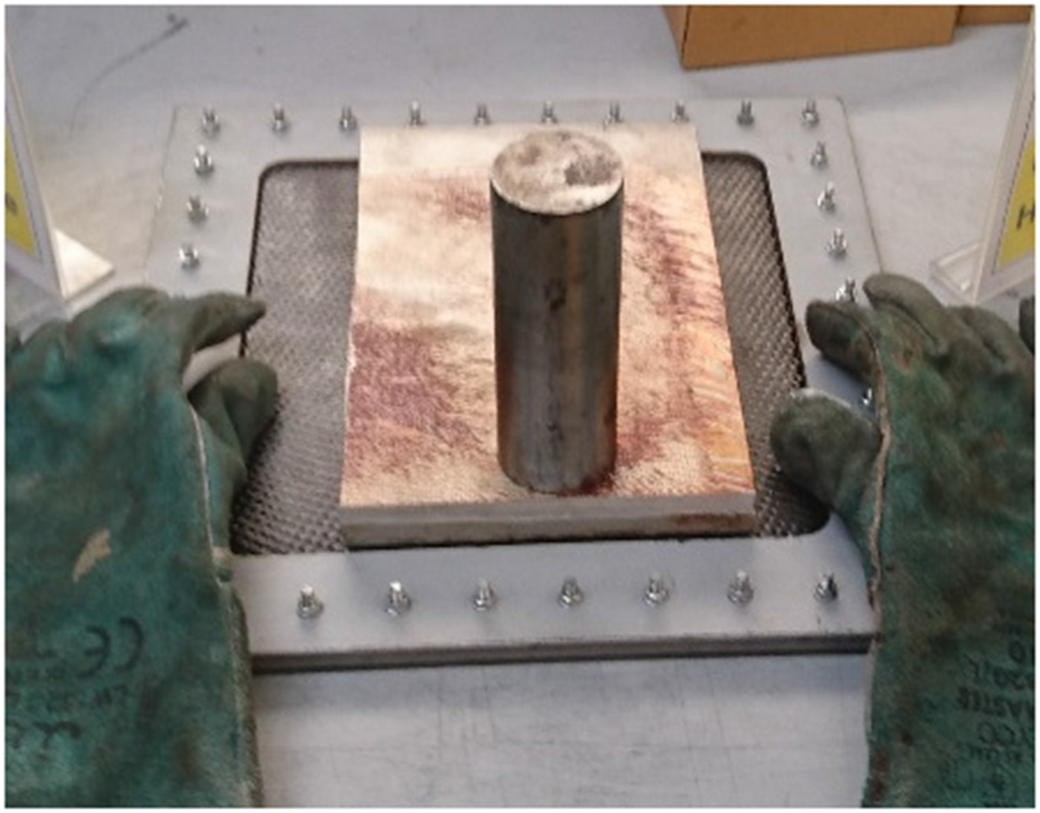
With the upper side of the pins flattened, the frame is then inverted, and the process repeated. This second press requires the sample to be supported directly below the fibre to prevent the flattened pin ends from being pushed through the part. This process is illustrated in Figures 5 and 6.
Stage 2 of refined press process. Example of part undergoing stage 1 press.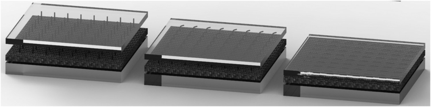
With both sides flattened the part can then be subjected to the same single-step process using the RTM tool to compress the part to the final thickness for infusion.
The aim of this process is to prevent the sliding of the layers that results in a shallow pin progression in the single-stage process. µCT analysis of the single-stage process (Figure 7) shows the extent of this issue.
µCT image of pin progression from the single-stage process.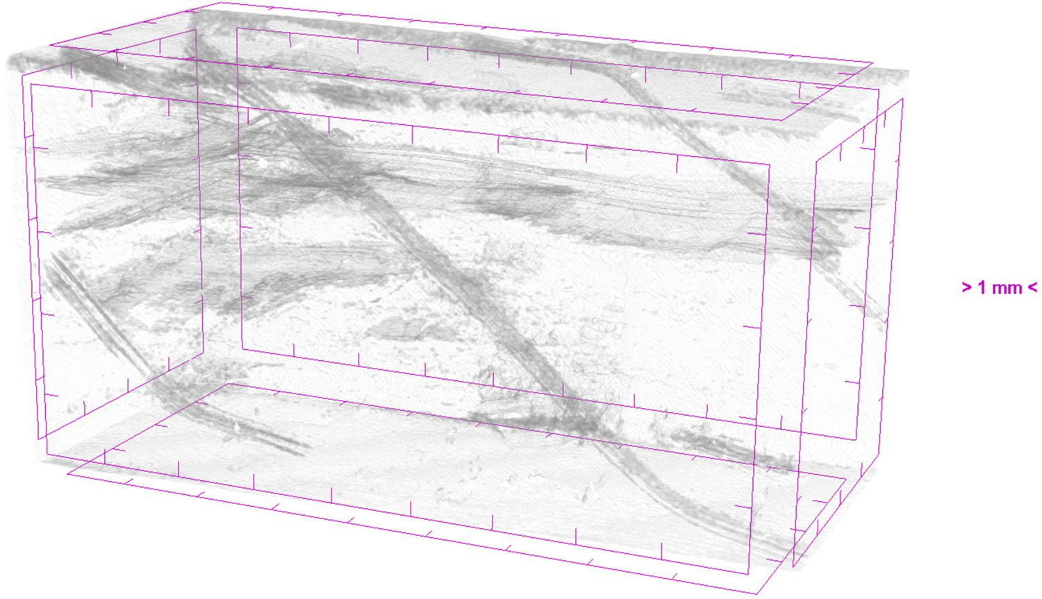
The refined multi-press process shows improvement (Figure 8). The pin progresses at a significantly steeper angle through the part. However, there is some level of bending in the pin. The cause of this is the compression of the part during the final press. This press is necessary for the RTM process to compact the part to the tool thickness for infusion. As the ends of the pins are flattened, they do not shift and as such the compaction results in the bending of the pins.
µCT image of pin progression in the multi-stage process.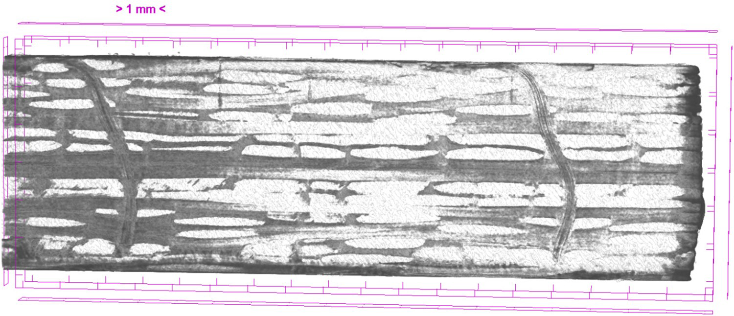
Mode 1
Mode 1 samples were conducted under a modified version of ASTM D5528 [21]. Samples of 25 mm width and 125 mm length were waterjet cut from the plaque with the pre-crack approximately 70 mm from the load line. The pre-crack comprised of a folded layer of Richmond Aerovac ETFE film with the fold present at the crack tip. 25 mm hinges were bonded to the part using Araldite 2014–2012 adhesive and constant crosshead displacement loading of 3 mm min–1 was applied by an Instron 5500R with a 5kN load cell and wedge grips. The sample hinge is mounted in the upper grip with load and then zeroed to account for sample weight. The lower hinge is then mounted in the sample grip and the system manually jogged to zero load and in this position, the displacement is zeroed before test start.
The test recorded using a Y3m high-speed camera (Figure 9) samples were marked at the end of the pre-crack with measurements beyond this point recorded digitally. The camera and Instron both record data points at a rate of 4 Hz. Data synchronisation between the intron load and camera image sequence is achieved by manually correlating the final image frame to the final recorded load before failure as an easily identifiable point from both data sources.
Mode 1 machine + camera setup.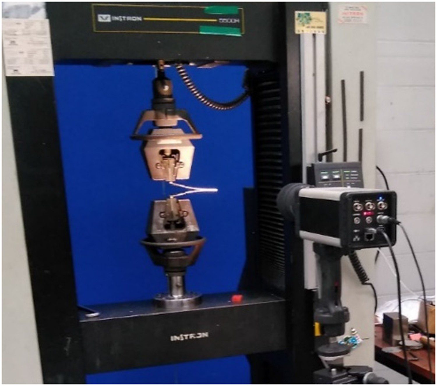
Post-test the images are processed to provide a representation of the interior profile of the crack (Figure 10). This profile is then analysed using a C# code to provide a side-length measurement in pixels corresponding to the length of the crack. A calibration measurement using the part thickness converts this into a measurement in mm.
Example of image processing output in white overlaid on original image.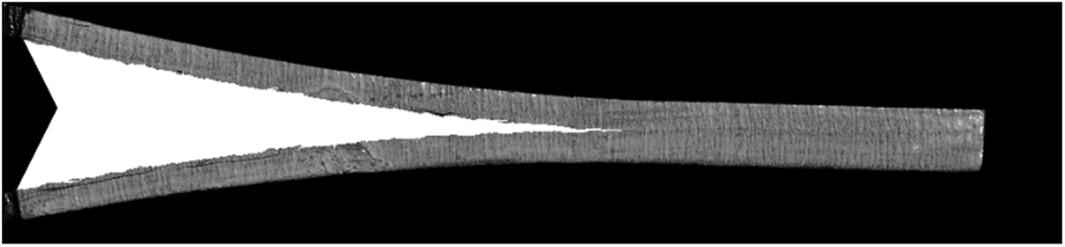
From initial trials samples it was found of the various methods of analytical adjustments to Modified Beam Theory (MBT) offered under ASTM D5528 [21], the Compliance Calibration (CC) method provided the most conservative values for GI hence all samples in this study use the MBT + CC method.
Results
Initial samples
2-D sample configurations.
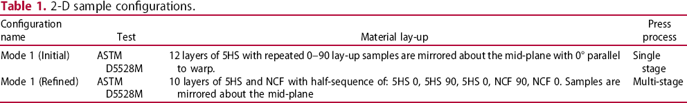
Figure 11 shows the initial samples post-test. The carbon pinned samples exhibited pin fracture despite showing no notable improvement in mode 1 resistance. This is due to the shallow pin angle inducing bending/shear in the pins rather than tensile failure at the crack plane.
Mean R-curves for initial mode 1 samples. Shaded areas denote standard error over five samples. Images of mode 1 samples post-test. Left-right: 2-D, carbon pinned, Kevlar pinned.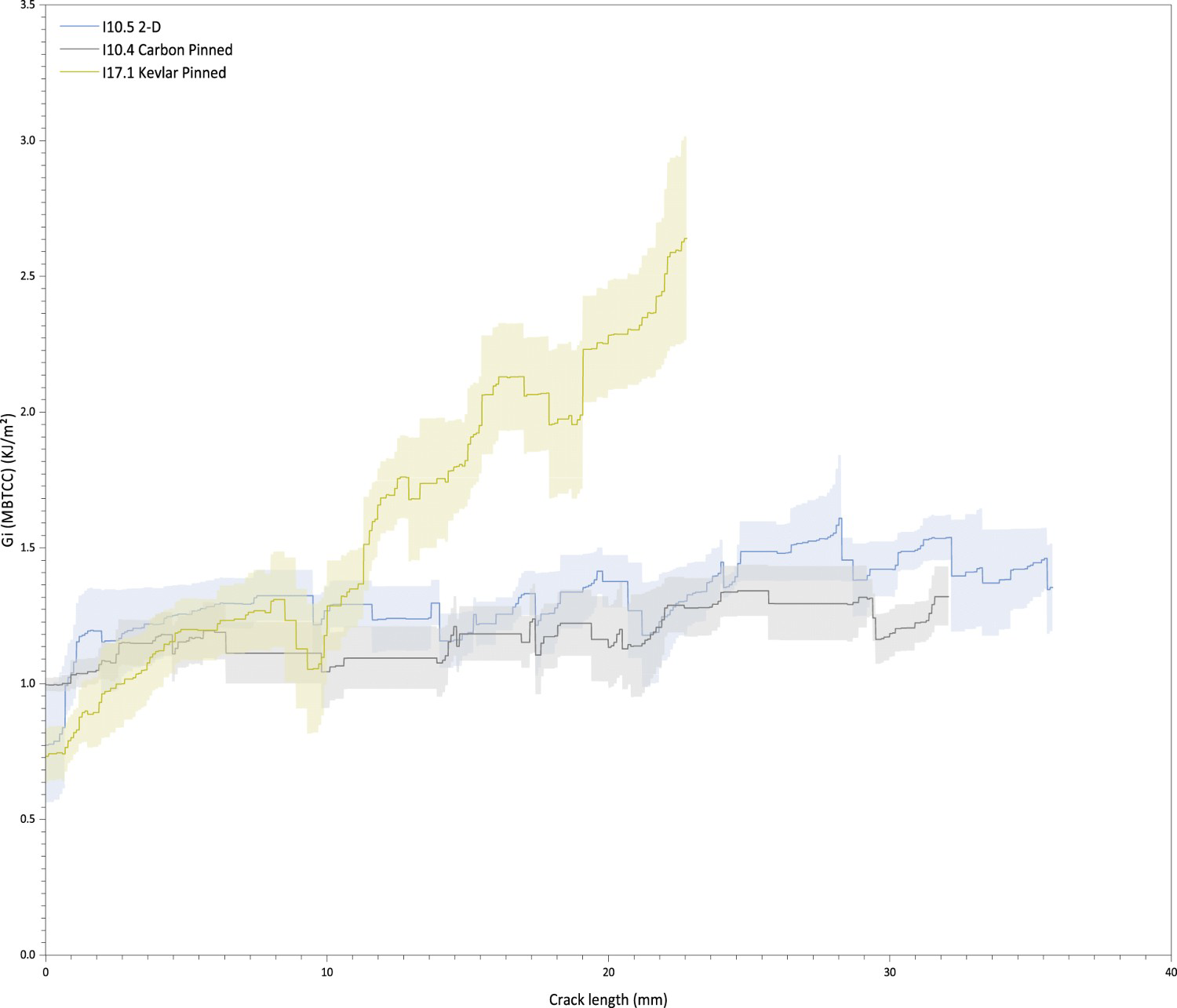
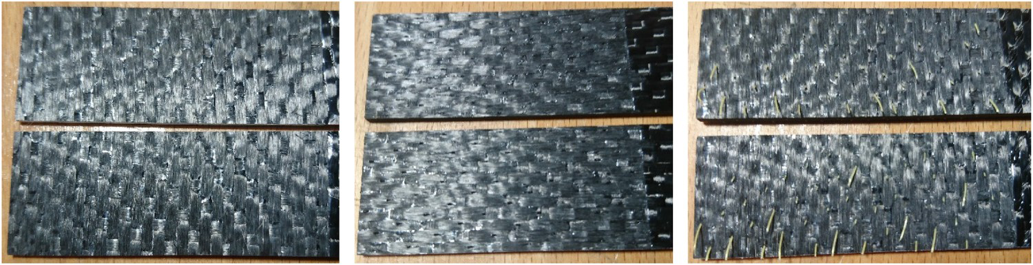
The Kevlar samples exhibited some degree of pull-out on the sample edges. Part of the reason for this is the angle of the pins was oriented perpendicular to the crack progression. As such pins near the edge of the part were only partially embedded allowing pull-out. However, some pins even in the centre of the part were also pulled out, indicating the pin fracture occurs near the surface of the part where the pin bends to conform to the surface.
Refined samples
The refined press method, combined with a change of lay-up to feature a UD interface, shows notable improvement. Samples with no pins (2-D), carbon pins and Kevlar pins are compared in Figure 13.
Mean R-curves for refined mode 1 samples. Shaded areas denote standard error over five samples.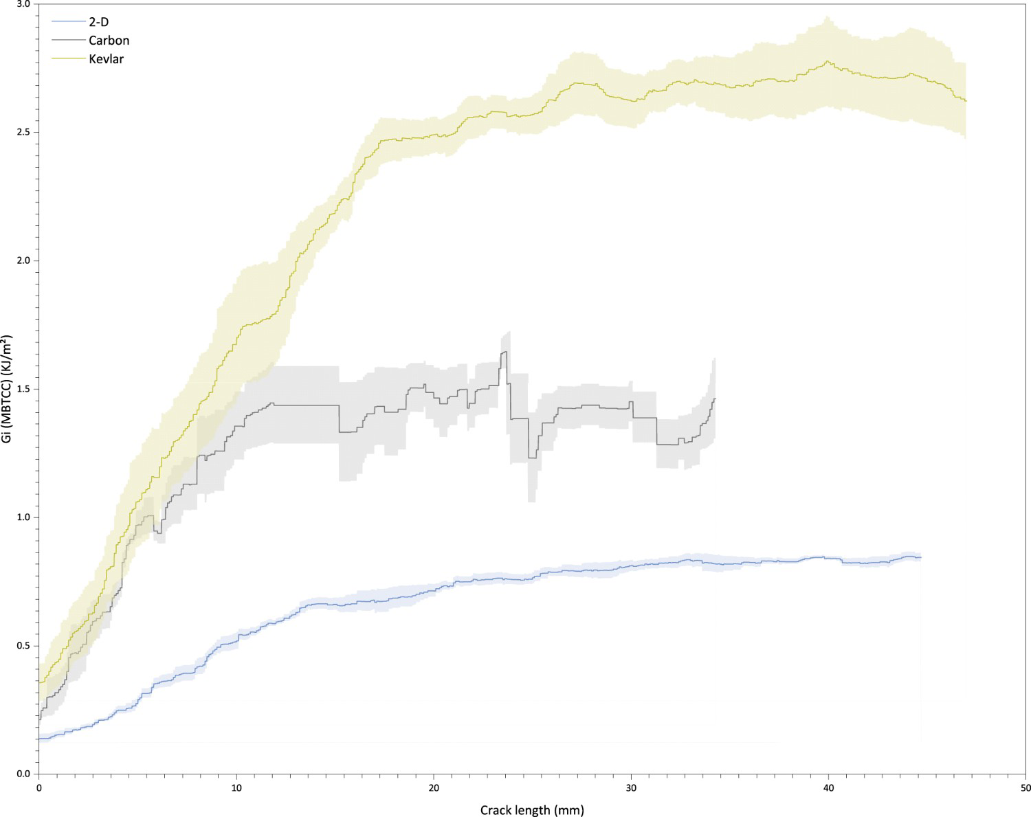
The 2-D samples exhibited smooth delamination, however the carbon pinned samples retained the stick-slip propagation. This is the result of the crack being arrested by a row of pins, with the sudden release of energy at pin fracture resulting in a corresponding increase in crack propagation. The Kevlar samples however did not experience this same phenomenon and instead exhibited the same smooth behaviour of the 2-D samples. It was observed during testing that the Kevlar pins exhibited some level of bridging (Figure 14).
Bridging observed with Kevlar samples.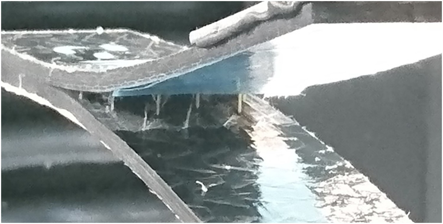
Figure 15 shows images of samples post-test. The carbon pinned samples showed fracture of the pins near, although not directly on, the crack plane.
Images of refined samples post-test. Left-right: 2-D, carbon pinned, Kevlar pinned.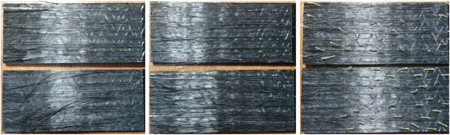
The Kevlar pinned samples however showed a high degree of pull out. observation of the top side of the part reveals that the flattened portion of the pin above the part was not disturbed indicating fracture occurs below the surface as illustrated in Figure 16. This is suspected as a cause of the smoother delamination observed as multi-pin support and frictional pull-out serve to absorb the energy release of individual pin fractures.
Illustration of fracture + bridging in Kevlar samples.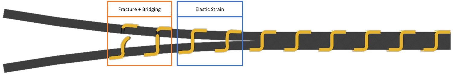
Conclusions
This pinning process shows promise as an alternate method of through-thickness reinforcement. The dry preform can be easily stored, handled, and manipulated into new topology while allowing the reinforcement to also conform to the new shape.
Figure 17 shows the average mode 1 results for both sample configurations. The initiation values, in this case, cannot provide meaningful conclusions, as the crack tip to first pin row separation could not be accurately controlled with the manufacturing methods used in this study.
Charts showing initiation (left) and propagation (right) mean values for single stage (top) and multi-stage (bottom) sample configurations.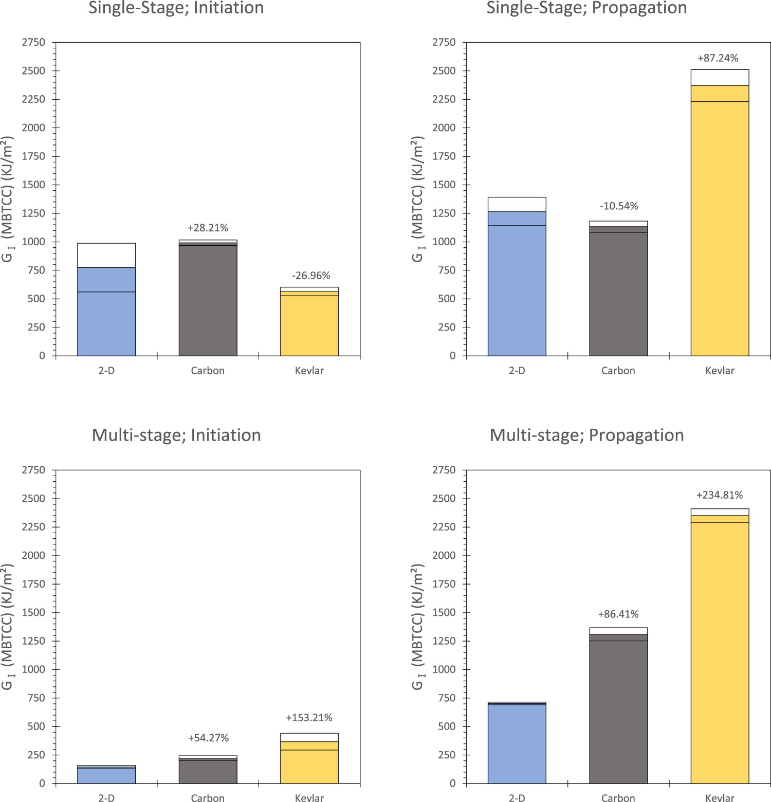
For propagation the initial single-stage samples were hampered by the use of woven fibre, this resulted in higher values for the unreinforced composite combined with a larger degree of variation. In the case of the carbon samples, it appears that the initial samples with shallow angle are not providing meaningful support to the part with the mean within variation of the 2-D samples. When moving to the multi-stage process the carbon pinned samples showed slightly improved toughness compared to the woven variation. For these samples, however, the strength improvement is now +86% compared to the 2-D baseline.
For the Kevlar samples, there were noteworthy improvements in both configurations. This is due to the multi-pin bridging and frictional pull-out seen during the failure. It has been noted in literature that pull-out can provide increased energy absorption compared to fracture both in the case of tufted [22] and Z-pinned [23] composites.
Comparison of tensile and mode 1 properties.
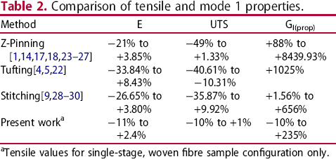
Tensile values for single-stage, woven fibre sample configuration only.
Further work
In terms of further work, there are three key areas of refinement that may be applied to this process. First, is the subject of automation of the pinning process to remove the time-intensive manual process conducted in this work. Second is the investigation of further mechanical properties in particular impact resistance and mode 2/mixed mode response. Finally, is the investigation of alternate pin construction, in particular the polymer element. One candidate for this which may prove beneficial is the use of the powder epoxy investigated by Noble et al. [20]. An Epoxy based pin, if combined with a laminate constructed of the same epoxy, might allow for the construction of through thickness reinforced preforms that can act as a ‘dry pre-preg’ without the storage requirements associated with conventional pre-preg materials.
Footnotes
Disclosure statement
No potential conflict of interest was reported by the author(s).