
Abstract
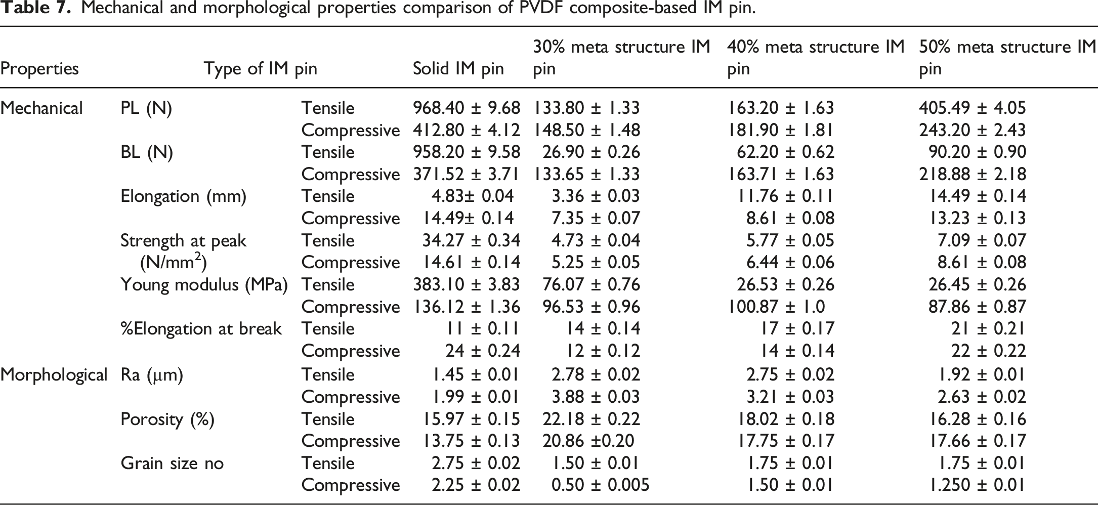
Some studies have outlined the use of 3D-printed polyvinylidene fluoride (PVDF) composite-based solid intramedullary (IM) pins with tunable mechanical (tensile, compressive, flexural, and torsional) properties for orthopedic applications. But hitherto little has been reported on the effect of meta-structure induced in 3D-printed IM pins for canines from the mechanical properties’ viewpoint. This study highlights the design, fabrication, and testing to mimic actual loading conditions in the canine femur bone on novel IM pin with meta-structure employed in different length zones (30%, 40%, and 50% of total gauge length) prepared by fused filament fabrication (FFF) of PVDF composite. The IM pin (of length 150 mm) has square threads (pitch 2 mm) at the distal end (ɸ7 mm, up to 60 mm in length), and V threads (pitch 1.5 mm) at the proximal end (ɸ6 mm, up to 30 mm in length). The IM pin was fabricated at the best setting (of the FFF process) suggested by the multifactor optimization (at nozzle temperature (Nt) 235°C, printing speed (Ps) 60 mm/s, and raster angle (RA) 45°). The result suggests that for the solid IM pins prepared at the optimized settings the observed elongation, peak load (PL), and break load (BL) during tensile and compressive loading were 4.83 mm, 968.40 N, 958.20 N, and 14.19 mm, 412.80 N, 371.52 N respectively. Whereas for 50% meta-structure the observed elongation, PL, and BL during tensile and compressive loading were 14.49 mm, 405.49 N, 90.20 N, and 13.23 mm, 243.20 N, 218.88 N respectively. For both tensile and compression loading (in this case study), better elongation was noticed for the FFF-based IM pin with 50% meta-structure and hence recommended for implantation in the canine femur bone. The results are also supported by scanning electron microscopy (SEM), and energy dispersive spectroscopy (EDS) based surface characteristics of the fracture sites.
Introduction
Meta structures frequently facilitate adaptation and flexibility in the case of implants and offer a framework that is higher-level coherent and may be adjusted to fit a variety of scenarios. 1 To make sure that the implant is well-tolerated by the host tissues, the meta structure must be carefully constructed. 2 The implant’s surface properties, such as its porosity and roughness, can influence how well it blends in with the surrounding tissues. A well-thought-out meta-structure will encourage integration with other tissues, or osseointegration in the case of bone implants, improving the implant’s overall functionality. 3 The manufacturing procedures should be taken into account while designing the meta structure. 4 IM pin is an orthopedic device that is used to repair fractures. IM pin offers stability, support, and aid in the healing process. These pins are placed into the medullary canal of long bones (such as the femur or tibia). 5 Internal fixation of fractures is frequently accomplished. IM pin gives the bone a strong internal skeleton that facilitates proper alignment during healing. 6 IM pins lessen the possibility of problems like nonunion or malunion by stabilizing bones throughout the healing process. Depending on the particular application, the pin’s design, material, etc. may change. While some pins are solid, some could have holes to allow for locking screws or greater bone integration. 7 To minimize bone resorption and guarantee that the load is properly distributed to the bone, designs may try to eliminate stress shielding. An IM pin’s meta-structure may be important in mitigating or eliminating stress shielding. 8 When an implant carries a disproportionate amount of the mechanical load, the surrounding bone experiences less stress, a process known as stress shielding occurs. Over time, this may cause bone resorption or weakness. The implant’s meta-structure can be made to more closely resemble the mechanical characteristics of the surrounding natural tissue to reduce stress shielding. 9 Improving osseointegration by altering the implant’s surface can aid in lessening stress shielding. Enhancing the implant’s integration with the surrounding bone can improve load distribution. Technological developments like additive manufacturing/3D printing make it possible to create implants that are customized for each patient. Because these implants closely resemble the mechanical characteristics of the original tissue, they may be customized to the individual’s anatomy, reducing the amount of stress shielding. 10
Custom IM pins and prostheses that fit each patient’s specific anatomical characteristics may be made by 3D printing. 11 Enhancing the fit, comfort, and performance of implants through personalization can benefit patients. Based on medical imaging data, surgeons may employ 3D printing to construct precise, patient-specific anatomical models. Surgeons may better envision intricate structures, plan operations, and rehearse techniques before going into the operating room with the aid of these models. 12 This may lower surgical risk and improve accuracy. The use of 3D printing 13 in medicine has several advantages, including improved research and teaching as well as more individualized patient care. 3D printing will probably become progressively more important in a range of medical applications as technology develops. 14
The PVDF is a polymer that has drawn interest in several medicinal and implant applications. 15 Even though it may not be utilized as frequently as some other materials, its qualities make it appropriate for implant applications. PVDF composite 16 (reinforcement with hydroxyapatite (HAp) 17 and chitosan (CS)) 18 is typically regarded as biocompatible, which means that the body can handle it well and that it does not cause any severe adverse reactions or immunological responses.19,20 For any material utilized in implant applications, this quality is essential to guarantee that the surrounding tissues are not harmed. PVDF is renowned for its formability and flexibility, which enable it to be molded into a variety of shapes appropriate for certain implant designs. Because PVDF is a piezoelectric material, the mechanical stress causes it to produce an electric charge.21,22 Due to this characteristic, PVDF is being considered for use in sensors and other devices that can translate mechanical information like pressure or movement into electrical impulses. 15 PVDF is chemically inert, it won’t react chemically with body fluids. PVDF is radiolucent, X-rays cannot pass through it. This enables clear imaging of the surrounding tissues, which can be helpful for implants that need to be seen by medical imaging methods like X-rays. 15 The strength and stiffness of the implant must be enough to sustain the mechanical stresses involved in the orthopedic application. 23 Implants utilized in joint stabilization or fracture fixation, for instance, must offer sufficient support without deforming. Given that the implant will undergo cyclic stress throughout the canine’s regular activity, this is especially crucial in dynamic settings like joints where movement causes repetitive loading. 24 A balance between ductility and toughness is necessary for implants to resist breaking under rapid loads or shocks. This is particularly crucial in areas that experience torsional or bending stresses. It may be noted that precise mechanical characteristics are needed for an orthopedic implant in canines. This may vary depending on the kind of implant (plates, screws, joint replacements, etc.), location in the patient’s body, size and breed of the canine.12,25
The literature review suggests that various studies have outlined the use of 3D-printed PVDF composite-based IM pins with tunable mechanical (tensile, compressive, flexural, and torsional) properties for orthopedic applications. But hitherto little has been reported on the effect of meta-structure on the mechanical properties of 3D-printed IM pins for canine. This study highlights the design, fabrication, and destructive testing (tensile and compressive to mimic actual loading conditions in canine) of novel IM pin (with meta-structure having different length zones (30%, 40%, and 50% of total gauge length) prepared by FFF of PVDF composite as an extension of previously reported studies.26,27
Materials and methods
The extrusion-grade PVDF granules were purchased from the local market (Solvay, Gujarat, India) in pellet form. The pellets have a glass transition temperature of ≈−40°C, a melting point of 170°C–180°C, and a density of 1.75 g/cm3. The chitosan (CS) and hydroxyapatite (HAp) (colorless and brittle) were procured from Marine Hydrocolloids, Kochi, Kerala, India. The HAp having nanoparticle size, typically in the range 30 ± 4 to 60 ± 6 nm in diameter was used. The CS powder having >85% deacetylation (DA), pH-8.1, 100±8–200 ± 8 nm particle size was used. The percentage of reinforcement (8%HAp-2%CS) in the matrix (90%PVDF) is based on the melt flow index (MFI) reported in previous studies. 27
Fabrication of the study sample and test used
The PVDF composite was prepared in-house, and its rheological (MFI: 1.24 ± 0.014 g/10 min), mechanical (Young’s modulus: 889 ± 4.5 MPa), dielectric (9.6 ± 0.3 at 20 MHz), and thermal (heat capacity 29.45 ± 1.3 J/g, crystallinity 37.66 ± 1.4%) properties were ascertained in line with previously reported study.
27
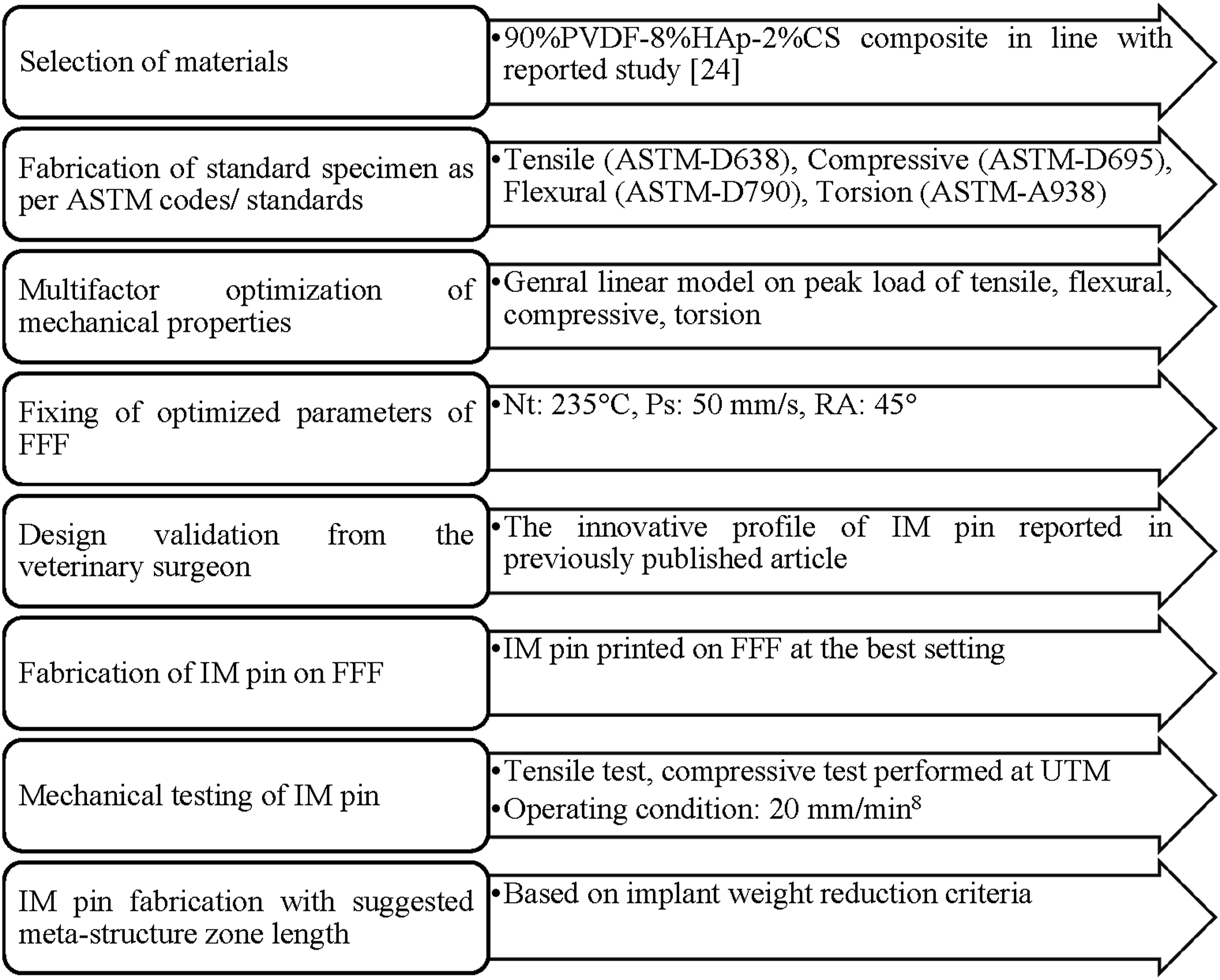
Figure 1 shows the process for the fabrication of a PVDF composite matrix. Further, Figure 2 displays the methodology adopted for this investigation. The tensile and compressive test was performed on a universal tensile tester (UTM) (Make: Shanta Engineering, Pune, India) at 20 mm/min, with a gauge length of 60 mm. The IM pin in the current case study was 150 mm in line with the previous study.
6
To facilitate drilling into the cancellous bone (upper part of the femur bone), the tip was made tapered. The IM pin (of length 150 mm) has square threads (pitch 2 mm) at the distal end (ɸ7 mm, up to 60 mm in length), and V threads (pitch 1.5 mm) at the proximal end (ɸ6 mm, up to 30 mm in length). For the compressive test, two holders were designed as per the dimensions of the IM pin ends. The holder for the proximal end has an internal cavity of ɸ6.40 mm and the holder for the distal end has an internal cavity of ɸ7.20 mm. The IM pin holder was printed with ABS thermoplastics materials on a U-printer (Make: Stratasys, USA) at 0° orientation, infill density of 100%. After the tensile and compressive test, the fracture site was analyzed by using SEM images captured at ×100 and 4 kV operating voltage. Process for preparation of PVDF composite matrix. Adopted methodology.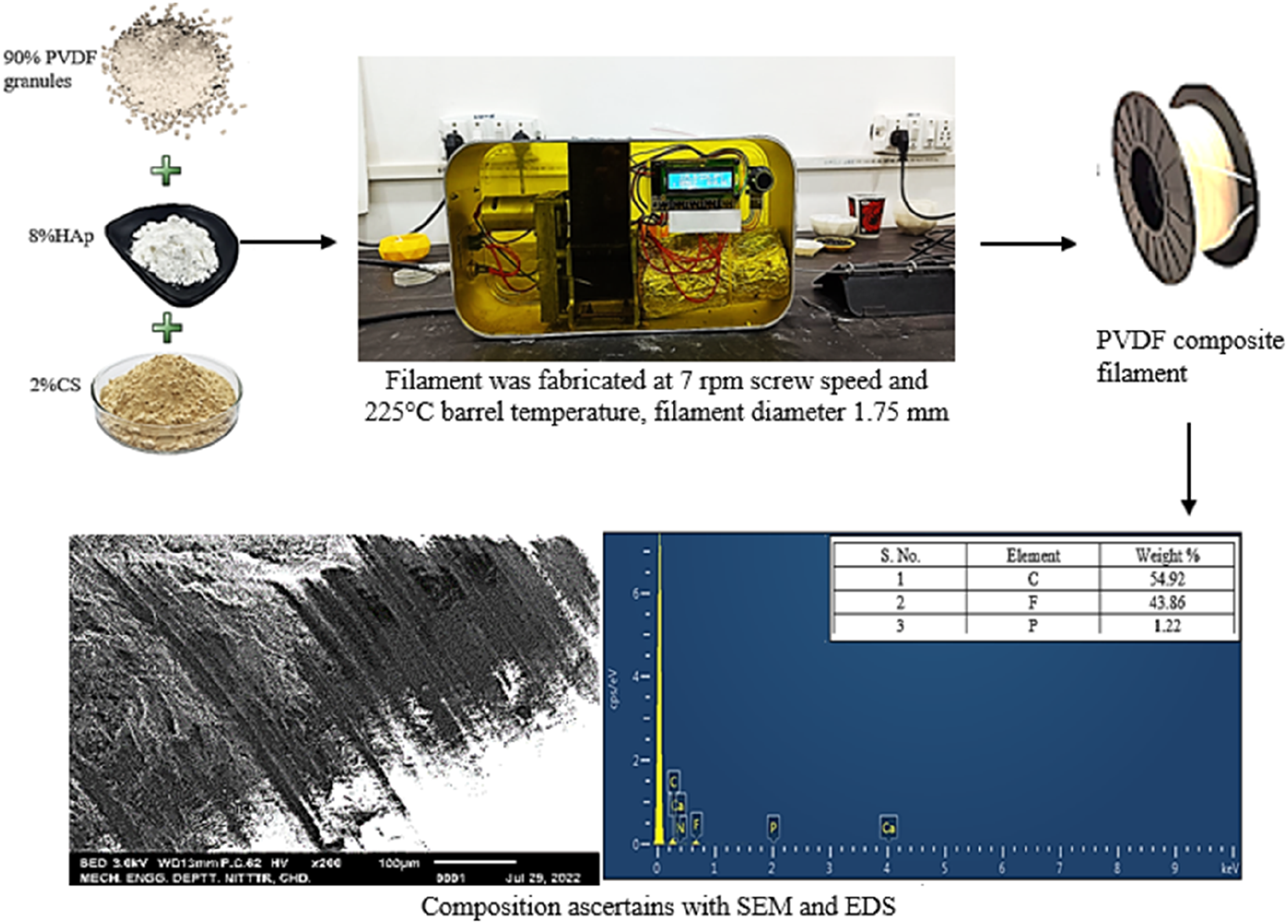
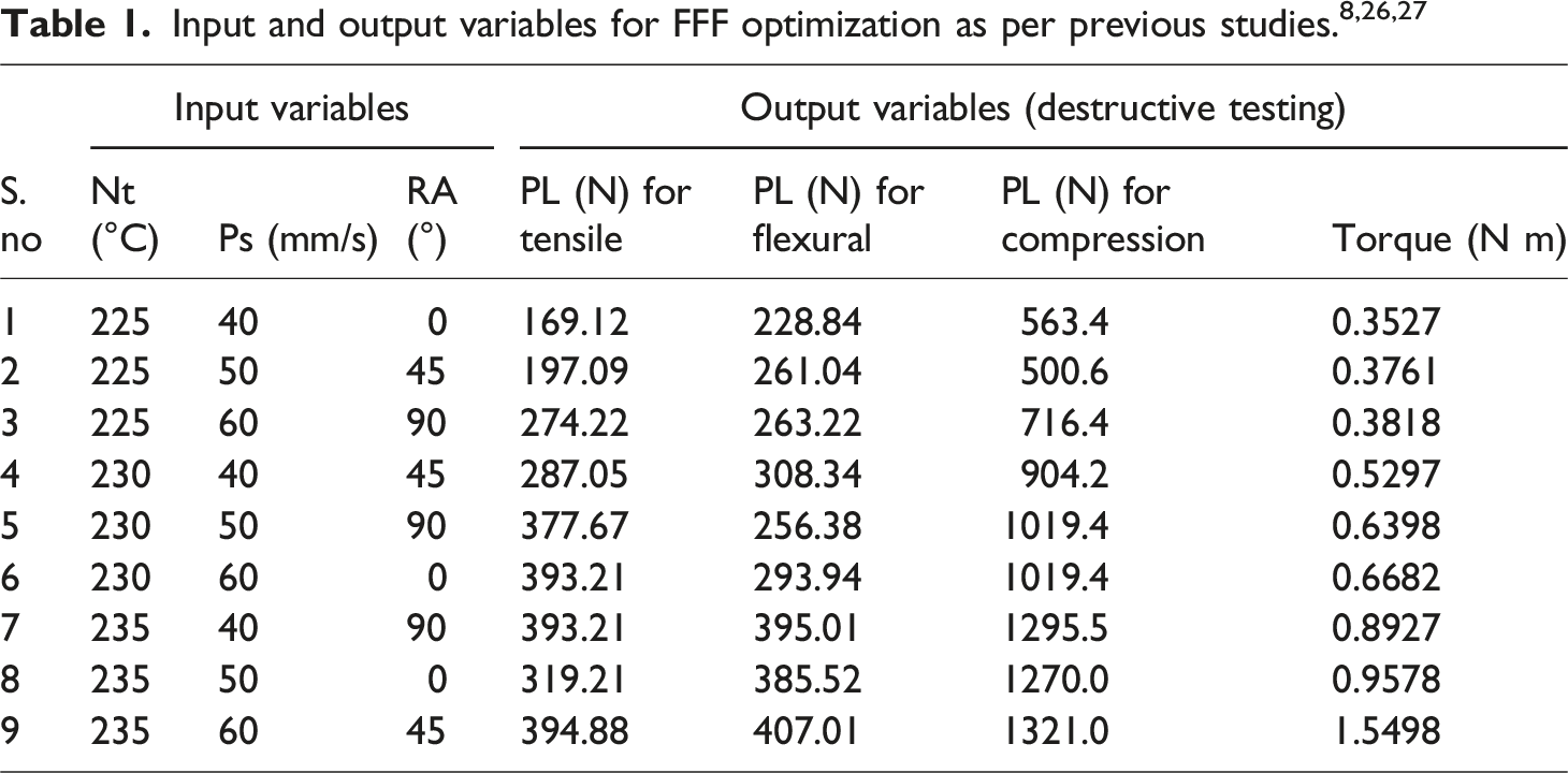
Experimentation
Parameters selected for the general linear model.
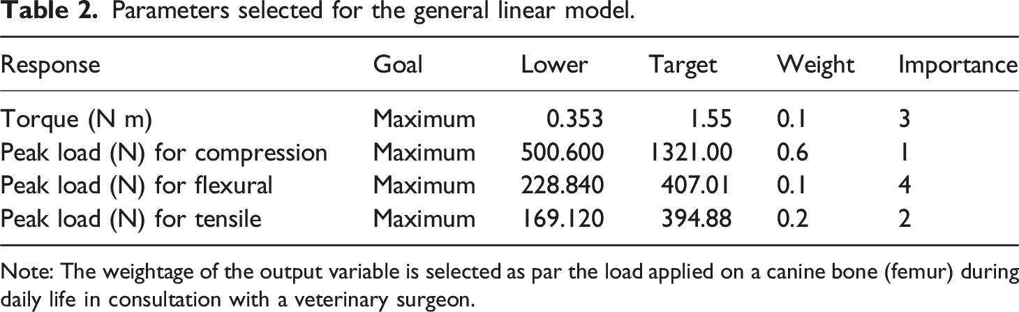
Note: The weightage of the output variable is selected as par the load applied on a canine bone (femur) during daily life in consultation with a veterinary surgeon.
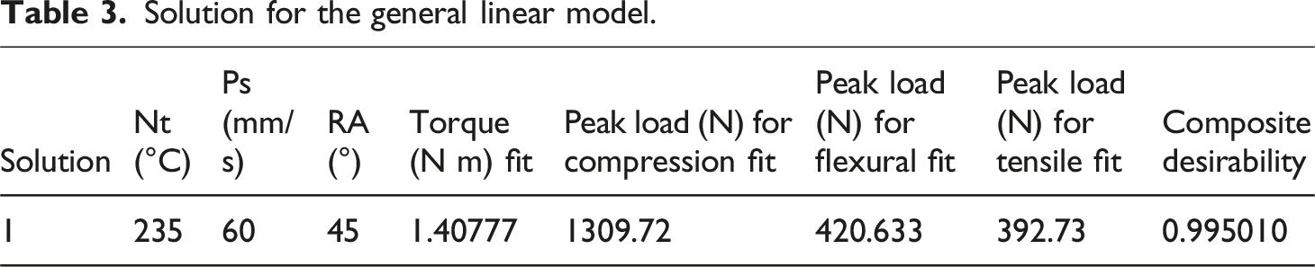
Solution for the general linear model.
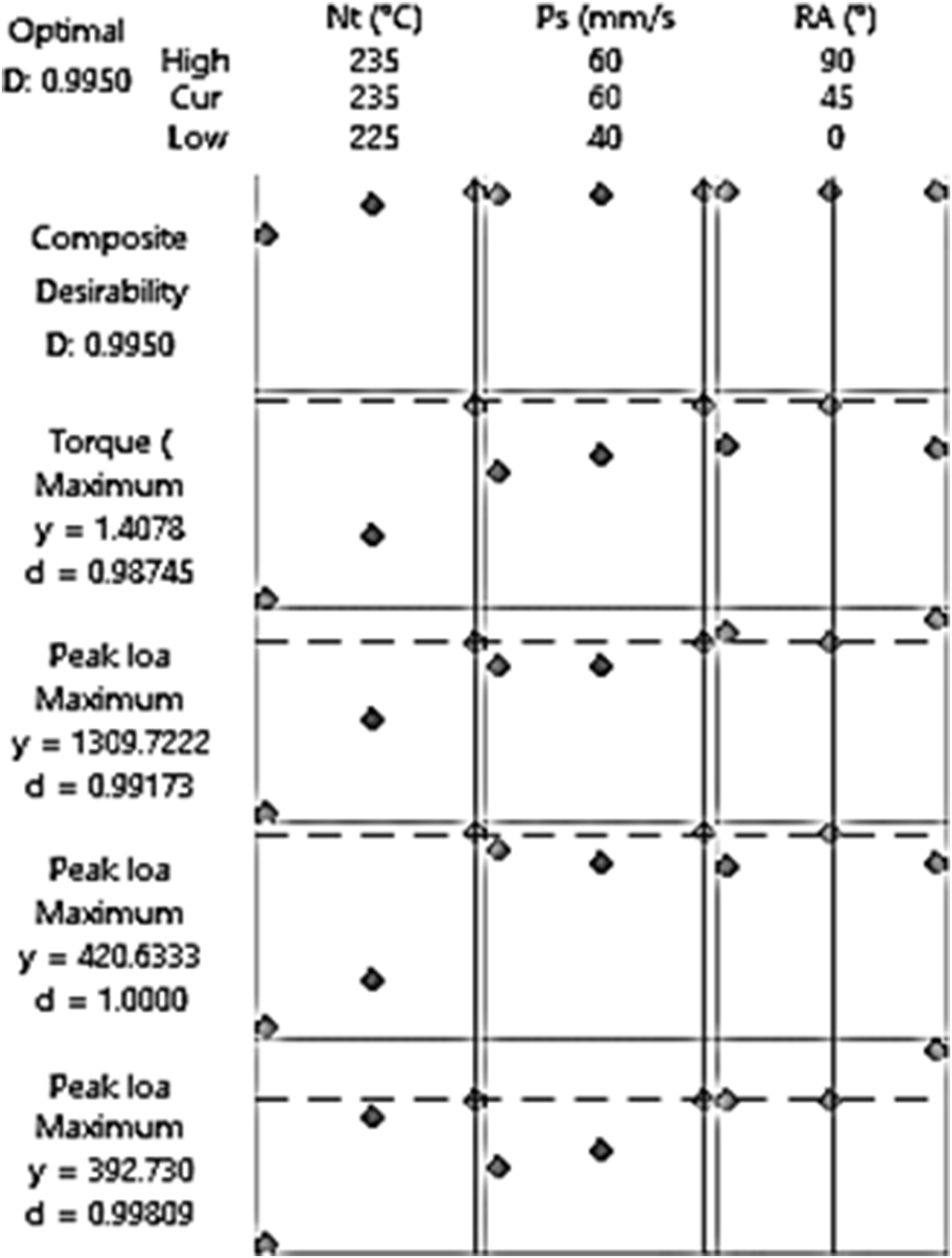
Composite desirability plot of multi-factor optimization on mechanical properties of IM pin. Note: In this study, a composite desirability plot was drawn for multifactor optimization for various mechanical properties of IM pins. However other approaches like multi-criteria decision making (MCDM) may be used for better decision making.
For the confirmatory experiments, the IM pins were fabricated at the optimized setting suggested by the general linear model (Nt. 235°C, Ps. 60 mm/s, and RA 45°). The peak load observed for compressive, tensile, and flexural loading were 1320.0 ± 5.2 N, 357.04 ± 3.5 N, and 401.01 ± 2.9 N respectively. The torque was observed as 1.22 ± 0.6 N m.
According to the reported literature, the IM pin’s diameter should be between 50 and 70% of the bone’s intramedullary cavity.
6
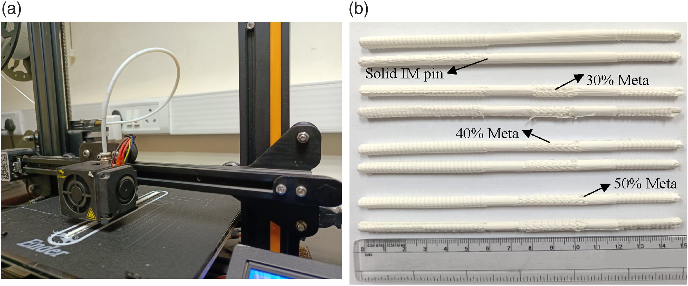
The pin in the current case study was 150 mm long in line with the previous study. To facilitate drilling into the cancellous bone, the tip was tapered (Figure 4(a)). After designing the IM pin in SolidWorks software, the CAD file of the IM pin was converted into a.stl file format. This was further proceeded in open-source Ultimaker Cura 4.11.0 software to insert the meta structure of the desired length. The meta-structure was inserted in the middle of a 60 mm solid length zone (without a threaded portion). The 30%, 40%, and 50% meta structures were selected based on the concept of reduced weight of foreign bodies as shown in Figure 4(b). The PVDF composite-based IM pins were printed on FFF at the best setting (Nt: 235°C, Ps: 60 mm/s, RA: 45°) suggested by the multi-factor optimization (general linear model) as shown in Figure 3. The two sets of IM pins with 05 repetitions were successfully fabricated on FFF (by using line pattern as infill in the selected zone length/area and by putting the wall count as zero in the Ultimaker Cura 4.11.0 software) for tensile and compressive tests as shown in Figure 5. (a) Design IM pin in Solidworks, (b) slicing of IM pin in Ultimaker Cura 4.11.0. Note: In this study, a continuous meta structure (in one zone/area) was provided (Figure 4(b)), the same may be provided in two parts/zones. However, stress concentrations may occur at the points where the meta-structure is divided, making the material more prone to failure under mechanical loads. (a) 3D printing of PVDF composite IM pin, (b) 3D printed of IM pin for tensile and compressive test. Note: The tiny extended part like a pin near the meta structure was seen due to the change in the continuous printing (solid) to meta structure printing. These may be removed manually without any special effort.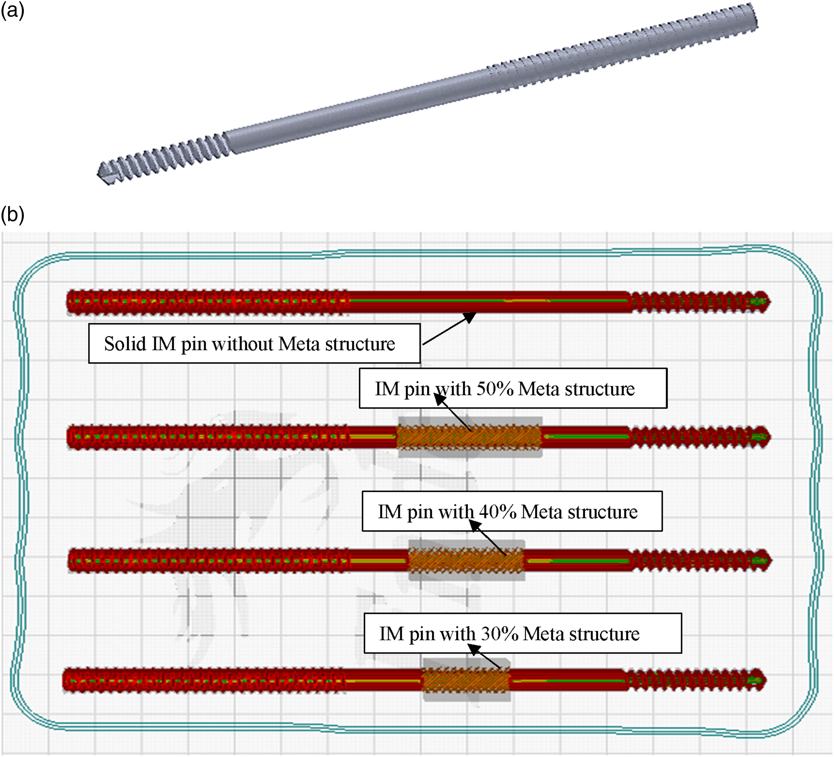
Results and Discussion
After the fabrication of the PVDF composite-based IM pin through the FFF process, mechanical testing was performed (Figure 6). In this study, the cross-head speed in the tensile test was taken as 20 mm/min. It may be noted that when the cross-head speed is increased, the strain rate also increases. High strain rates can lead to different mechanical behaviors in polymers compared to lower strain rates. In general, increasing the cross-head speed tends to result in higher tensile strength for polymers. This is often attributed to the fact that polymers, being viscoelastic materials, may exhibit strain rate sensitivity. Now, if the speed of the cross-head is reduced from 20 mm/min to 3 mm/min, the strain rate experienced by the PVDF composite during the test would decrease. This reduction in strain rate might lead to a decrease in tensile strength because the thermoplastic often exhibits time-dependent behavior due to viscoelasticity. Slower cross-head speeds allow for more time-dependent processes to occur, such as molecular relaxation, which can lead to a decrease in tensile strength. In the present study, the high strain rate conditions may mimic crash applications, which will be close to jerks, etc. experienced by patients that is canines while galloping. Tensile test of PVDF composite-based IM pin at UTM.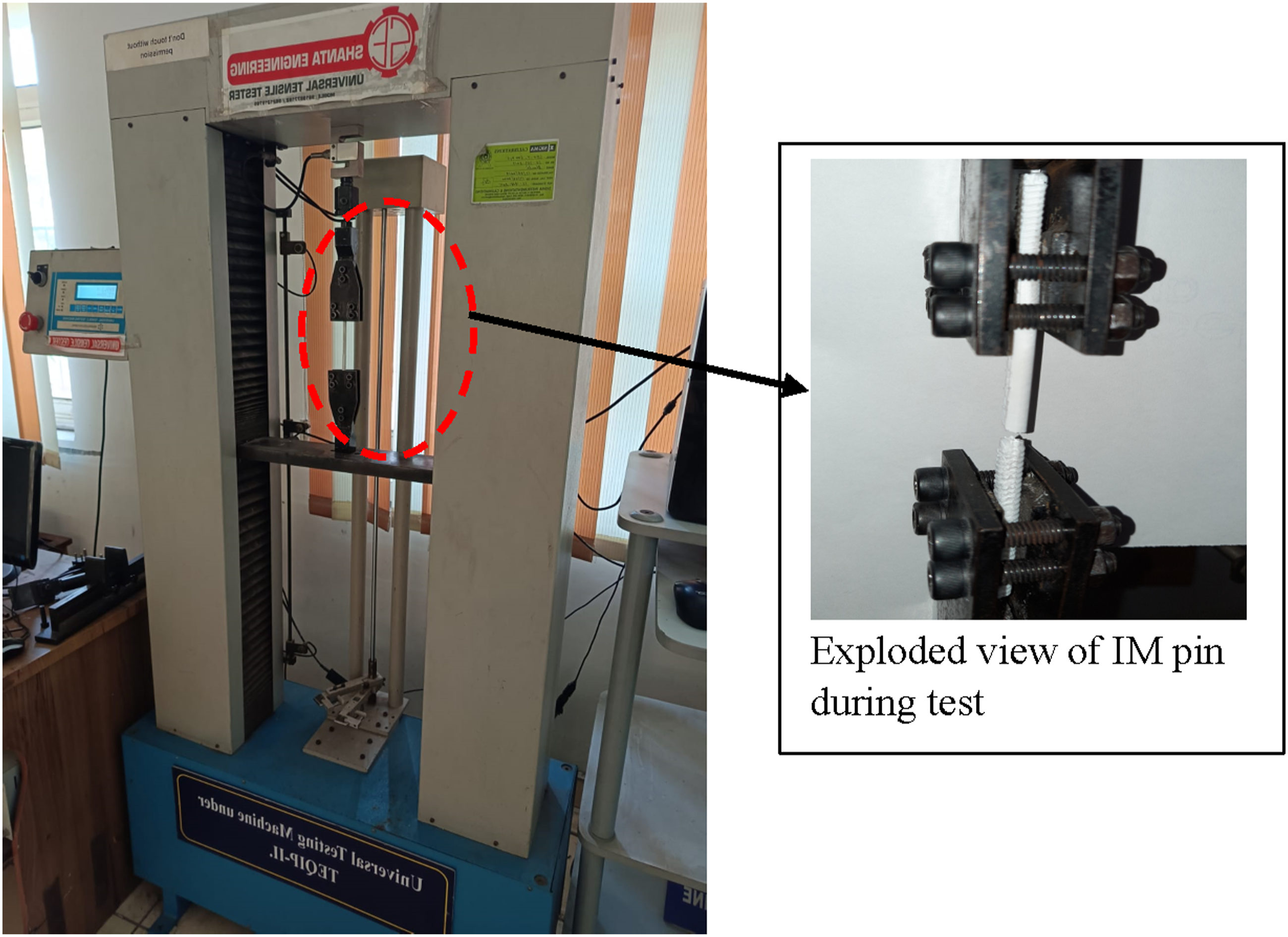
The load versus displacement plot is shown in Figure 7. The solid PVDF composite-based IM pin had the maximum peak load (958.20 N) but elongation was minimum (4.83 mm). On the other hand, it has been observed that with the increase of meta-structure zone length, an increase in elongation, and peak load takes place. The IM pin having maximum elongation may be considered a better solution for reducing stress shielding issues that occur after implantation in the canine. Load versus displacement of IM pin under tensile test.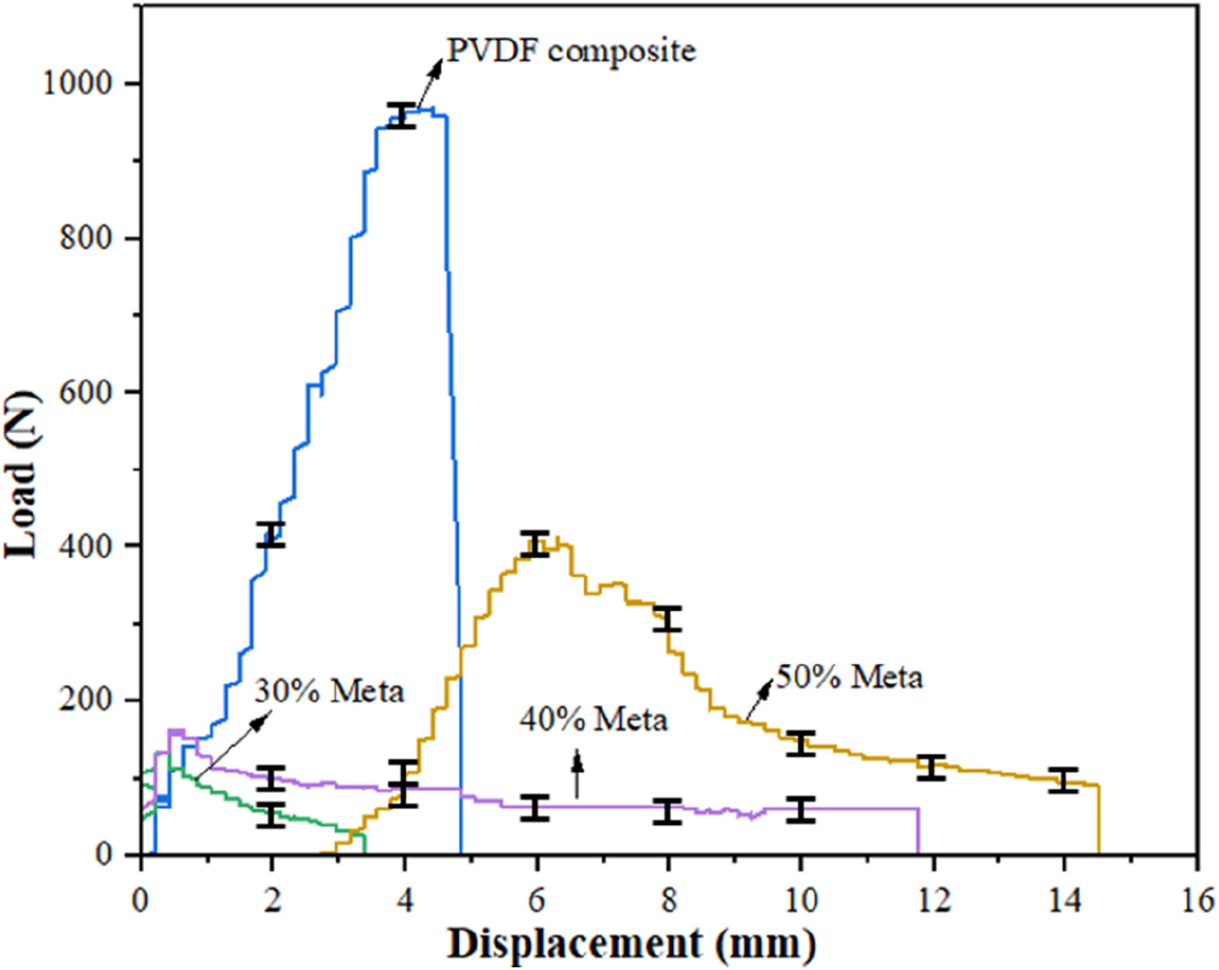
IM pin under tensile loading.
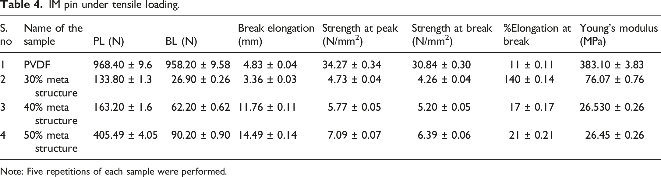
Note: Five repetitions of each sample were performed.
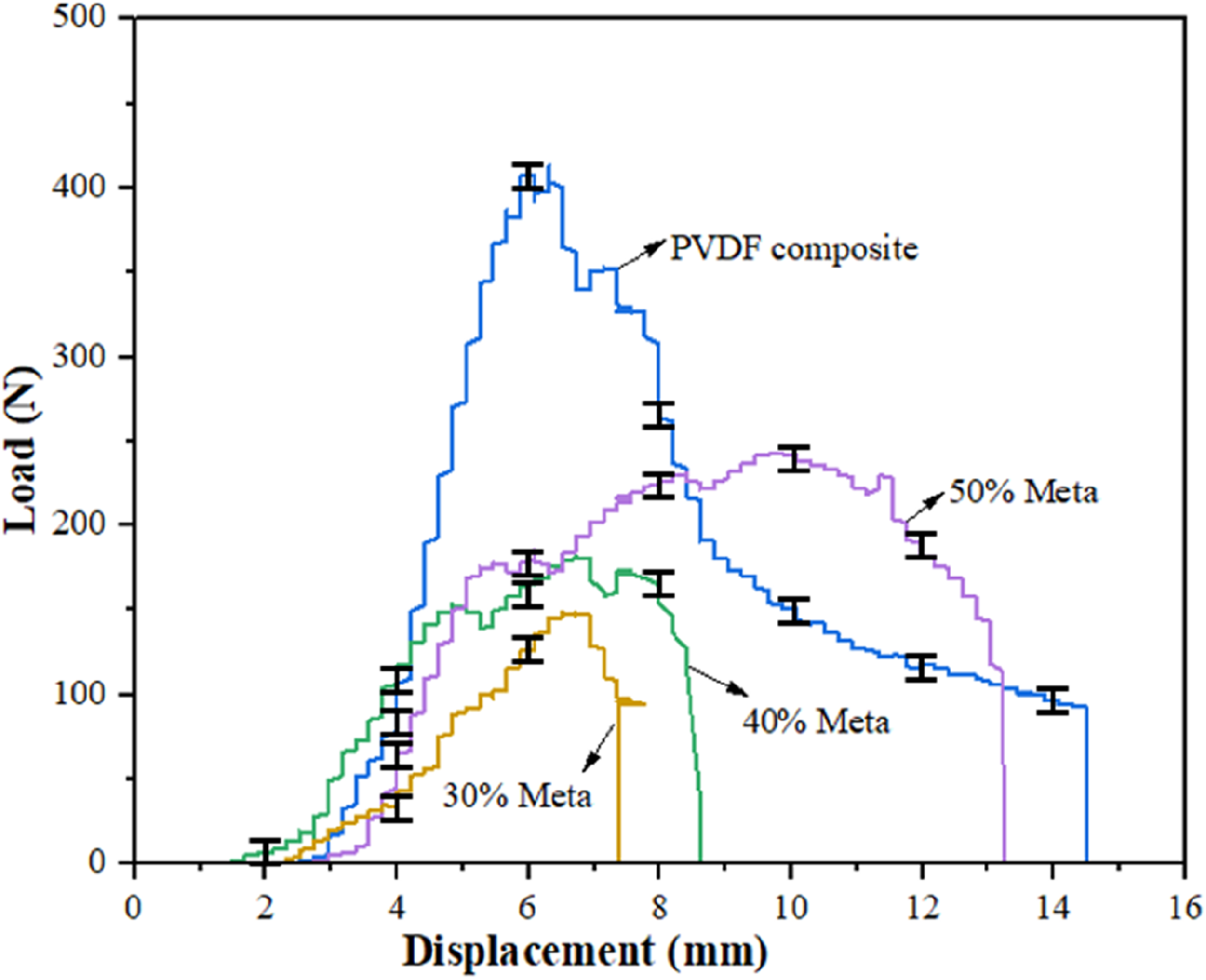
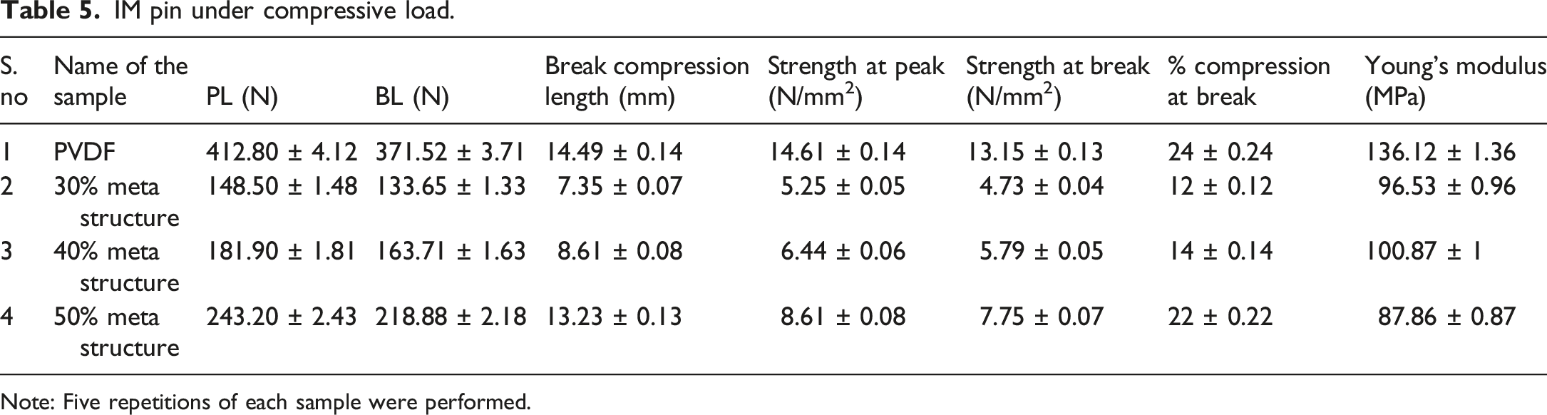
For compression testing, an IM pin holder was designed in SolidWorks software (Figure 8) to hold the IM. The assembly of the PVDF composite IM pin with ABS holder is shown in Figure 8(e). The PVDF composite IM pin underwent a compressive test on UTM Figure 8(f). The load versus displacement plot is shown in Figure 9. The compressive result of the PVDF composite IM pin is shown in Table 5. The solid PVDF composite-based IM pin has the maximum peak load (412.18 N). The meta-structure was inserted into the IM pin, it was observed that the meta-structure length increases with an increase in compression length and at the same time peak load decreases. The IM pin having maximum compression length is best for the reducing stress shielding problem that occurs after implantation in the canine. (a) Drawing of the smaller end of IM pin, (b) drawing of the larger end of IM pin, (c) 3D model of smaller end, (d) 3D model of larger end, (e) 3D printed IM pin with both holders, (f) compressive test on UTM. Load versus displacement under compressive load. IM pin under compressive load. Note: Five repetitions of each sample were performed.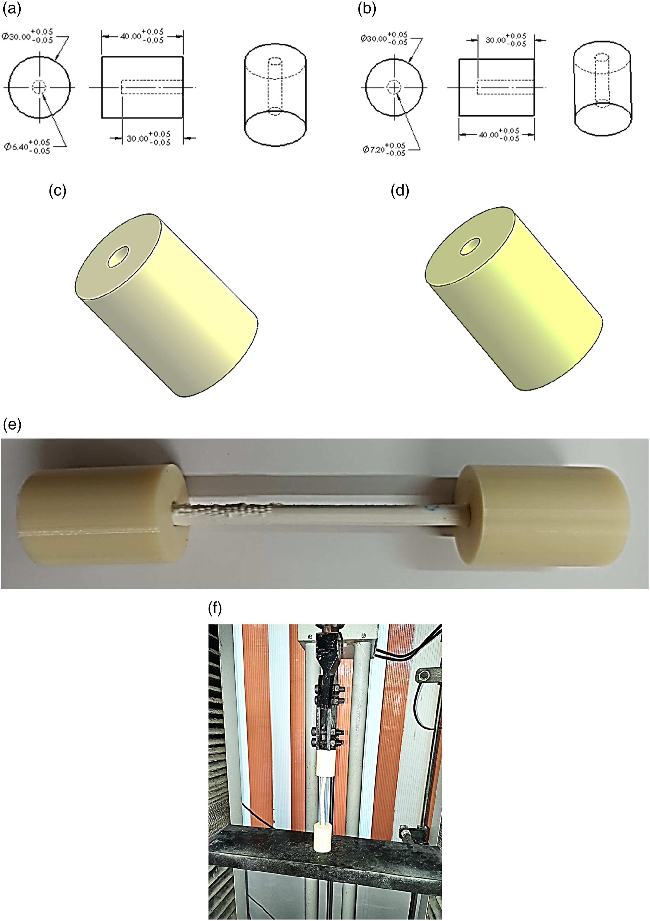
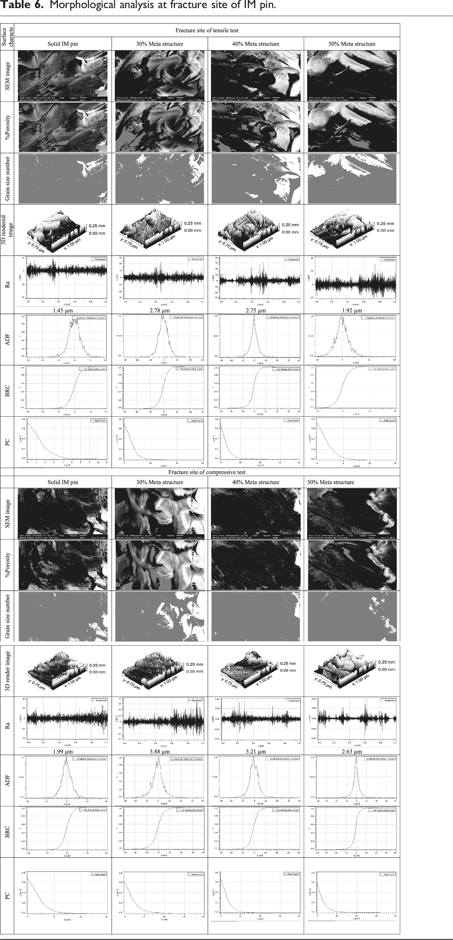
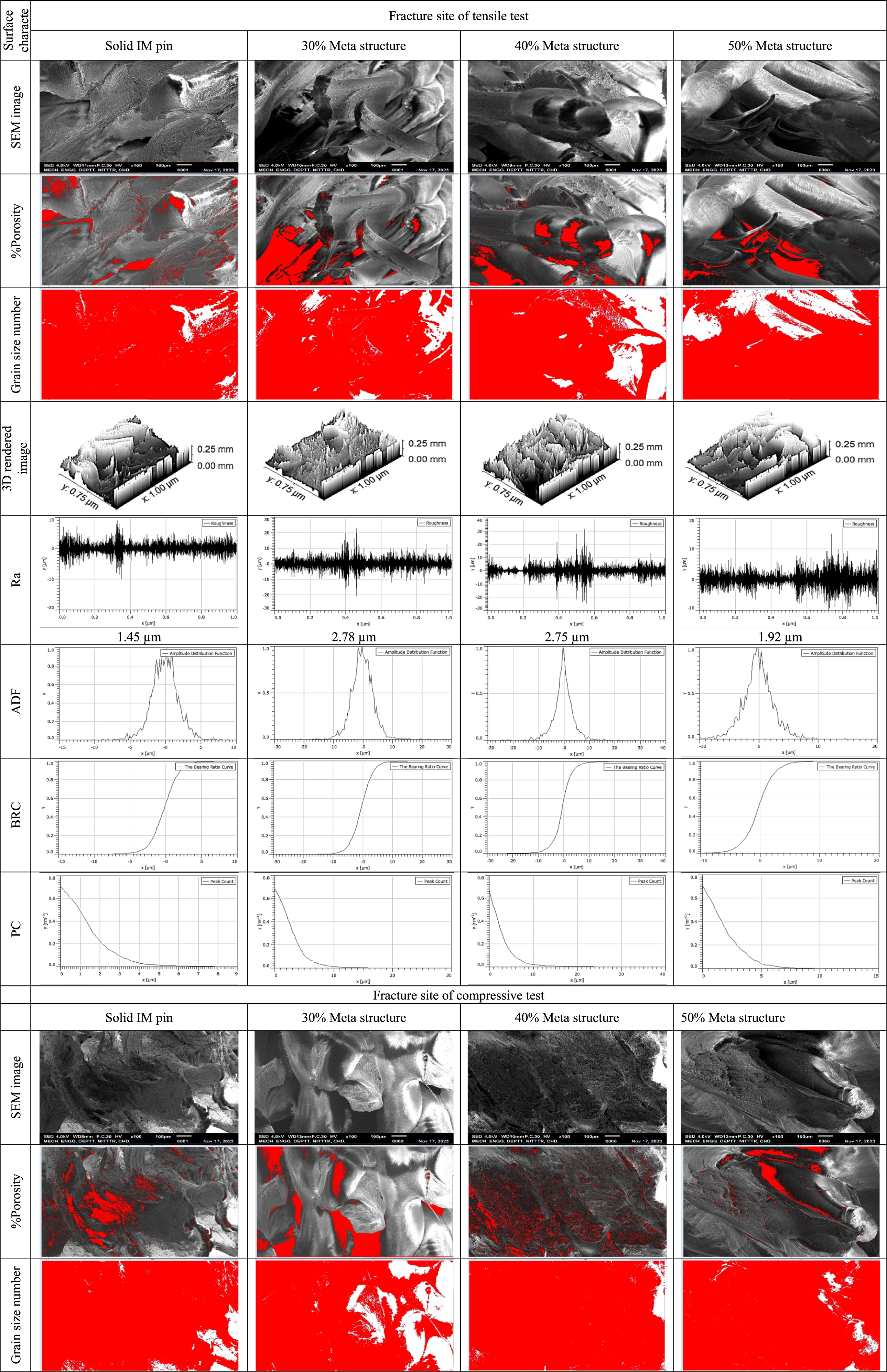
Morphological analysis at fracture site of IM pin.
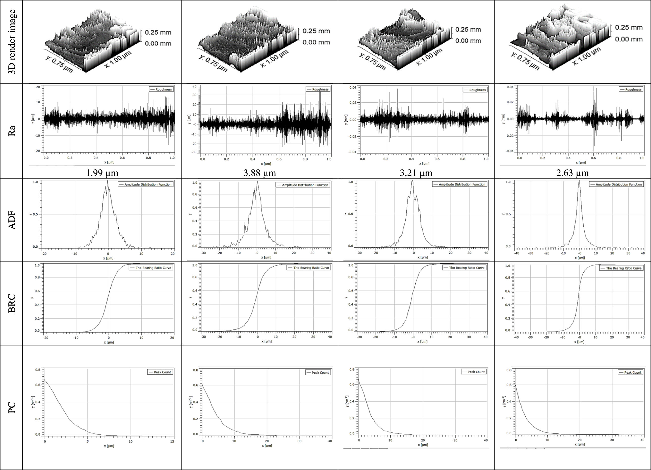
Mechanical and morphological properties comparison of PVDF composite-based IM pin.
Conclusions
This study highlights the design, fabrication, and destructive testing (tensile and compressive to mimic actual loading conditions in canine) of novel IM pin (with meta-structure having different length zones (30%, 40%, and 50% of total gauge length) prepared by 3D printing of PVDF composite. The IM pin was fabricated by 3D printing at the best setting suggested by the general linear model (Nt. 235°C, Ps. 60 mm/s, and RA 45°). The results suggest that maximum elongation was observed in the case of tensile test for the 50% meta structure IM pin, the elongation was 14.49 mm, peak load 405.49 N, and break load 90.20 N. In the case of the compression test elongation was observed in solid IM pins peak load, break load, elongation was observed at 243.20 N, 218.88 N, 13.23 mm, and 50% meta structure 412.80 N, 371.52 N, 14.49 mm respectively. The IM pins were also explored for higher zone length of meta-structure (more than 50%), but the observed Young’s modulus while tensile loading was very less (<10 MPa), which is not suitable for implant applications, and hence not recommended. For both tensile and compression loading (in this case study), better elongation was noticed for the FFF-based IM pin with 50% meta-structure and hence recommended for implantation in the canine femur bone. Further studies may be conducted to ascertain the effect of various meta-structures in IM pins along with in-vitro and in-vivo studies.
Footnotes
Acknowledgements
The authors acknowledge the research support provided by the National Institute of Technical Teachers Training and Research Chandigarh, and Prof. Ashwani Kumar from Guru Angad Dev Veterinary and Animal Sciences University Ludhiana. The authors are thankful to the Department of Science and Technology for funding under FIST Level-0, Project No. SR/FST/College-/2020/997.
Declaration of conflicting interests
The author(s) declared no potential conflicts of interest with respect to the research, authorship, and/or publication of this article.
Funding
The author(s) disclosed receipt of the following financial support for the research, authorship, and/or publication of this article: This work was supported by Department of Science and Technology under grant SR/FST/College-/2020/997.