
Abstract
In this research work, a piezoelectric sensor and actuator model was designed. Carbon fibre-reinforced polylactic acid (CF/PLA) composites were fabricated using the fused deposition modelling (FDM) technique using many parameters to achieve this goal. For instance, the primary key parameters were 0.1 mm (layer height) and 25 mm/s (print head). Besides, the fabricated samples were subjected to a tensile study. Besides, MATLAB® Partial Differential Equation (PDE) tool was used to develop a finite element analysis (FEA) model for the piezoelectric actuator using the experimentally tested results. The MATLAB® was also used to examine the geometry and tip deflection. The experimental works were carried out to measure the sample’s strain using piezoelectric sensors. This approach could be used to establish the accuracy of the model. The CF/PLA composites were fabricated using 20 wt.% of reinforcements. The experimental results and finite element simulation were good agreement on results. Results reported that the deflections of 6.5765 mm, 5.197 mm, and 7.6328 mm, respectively embedded with PZT 5J, PZT 5H, and PZT 5A.
Keywords
Introduction
Fused filament fabrication (FFF) is an additive manufacturing technique used in many industries, including aerospace, automotive, architecture, etc., requiring fabricating thermoplastic components. Amongst the methods, the FFF could be the user-friendly approach with minimal setup and operational requirements. 1 Most importantly, this technique allows quick and iterative design modifications without using expensive tools. 2 Different materials such as thermoplastics, thermosets, metals and ceramics could also be used to fabricate using the FFF technique. Thus, the fabricated parts can be filled with various needs and material properties. 3
Complex geometries and intricate parts can be developed using the FFF approach. 4 This is accomplished by the nature of layer-by-layer fabrication method, due to this, parts with internal cavities, undercuts and other features could be possible. Therefore, the fabrication of tubes, rods, and other structures also took place. 5 Even though the other manufacturing techniques such as CNC machining, injection molding or any other traditional machining approaches could be used to fabricate based on the specific requriements. 6
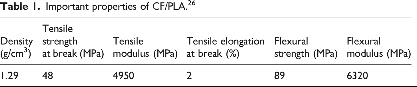
Carbon fibre (CF) reinforced polylactic acid (PLA) composites demonstrated experimentally to have lighter weights and superior tensile and flexural mechanical properties compared to PLA samples. 7 The strength, stiffness and impact resistance of PLA samples are enhanced when carbon fibres are reinforced. Many researchers reported that carbon fibre reinforced PLA samples could reduce the shrinkage and warping tendencies resulting in improved stability of the manufactured parts. Besides, the CF provides stability when they are incorporated within the matrices and enabling the manufactured parts to withstand higher temperatures without significant degradation. This property helps in using the applications that require resistance to heat.
Chao et al. 8 examined the mechanical and thermal properties of CF/PLA composites using the fused deposition modeling technique. The results reported that increasing the CF loading helped in improving the examined properties of the composites compared to the PLA samples. For instance, 5wt.% of fibre-loaded samples exhibited a higher tensile strength of ∼45 MPa, and 15wt.% of fibre-loaded samples showed ∼58 MPa in flexural strength. In another work, Nabeel and Marius 9 analyzed the mechanical performance of four different group of composite samples such as pure PLA, PLA reinforced with short CF, PLA reinforced with continuous CF. Researched reported that continuous CF reinforced samples exhibited 46% improvement in tensile strength than pure PLA and short CF reinforced samples. In flexural test also, the samples reinforced with CCF surpassed all other samples and reached 168.88 MPa. SEM results showed that the CCF samples exhibited good bonding between the fibres and matrix, while the short CF lacked interfacial bonding between the layers. Reverte et al. 10 analyzed 3D printed short CF/PLA composite samples, varying the build orientation, and examined the mechanical, dimensional accuracy, and surface roughness using the FFF technique. They reported that on-edge and flat orientations exhibited superior mechanical performance. Additionally, it was observed that, although the CF/PLA samples showed improved performance, they exhibited brittle behavior by failing at a lower strain compared to pure PLA samples. Regarding dimensional accuracy, the addition of CF did not influence the bahavior. Heidari-Rarani et al. 11 optimized significant parameters for the reliable 3D printing of CF/PLA samples: fibre-to-matrix bonding, fibre feed along with matrices, sample cooling, and the optimum fibre diameter. The results indicated a 35% improvement in tensile and a 108% improvement in bending properties of the 3D printed samples compared to virgin PLA. Moreover, the study concluded that the designed 3D printer can produce high-performance parts for applications such as robotics and the automotive industry. Samykano et al. 12 investigated three major process parameters—layer height, raster angle, and infill density of acrylonitrile butadiene styrene samples. Researchers reported that the considered factors influenced the mechanical performance of the fabricated samples The optimized parameters were identified as an 80% infill percentage, 0.5 mm layer thickness, and a raster angle of 65°. Valerio et al. 13 analyzed the sandwich panels for weight reduction using a novel manufacturing technique. The researchers reported that the weight reduction could be achieved by varying process parameters such as the infill value. A limited sensitivity analysis compared the post-impact response of sandwich configurations with similar external shapes. However, layer densities varied due tvaried Based on this novel approach, weight reduction was reached up to 28% in sandwich structures.
Fuda Ning et al. 14 reported that CF/ABS samples exhibited improvements in mechanical properties compared to pure ABS samples due to the addition of CF. Tensile strength and Young’s modulus of the fabricated samples were observed to increase. Despite the increased toughness, yield strength, and ductility showed a decreasing trend. Among the various fibre-loaded samples, 5wt.% and 7.5wt.% of CF-loaded samples showed the largest mean values for tensile strength and Young’s modulus. In another study, Rafael et al. 15 analyzed the mechanical properties, such as tensile modulus, Poisson’s ratio, shear modulus, and associated strength properties of short CF/PLA samples fabricated using the FDM technique. Based on the deposition direction, the authors labeled the samples as 1 and 2. The deposition direction was designated as 1, and a direction perpendicular to it as 2. The CF/PLA samples exhibited lower strain compared to pure PLA. Fracture surfaces were also examined using SEM.
A Piezoelectric sensor embedded composite within the framework performed dual functions of actuation and sensing. Hamilton’s principle affects how the structure’s mechanical energy is transferred to the electrical energy of the piezoelectric material, which is made of that material. 16 The ability of piezoelectric materials to transform electrical energy into mechanical energy and vice versa is its most important attribute. This feature is visible in various crystalline materials, including lead zirconate titanate (PZT) ceramics, where it has found practical application in sensors and actuators. 17 The connection of the constituent phases of piezoelectric ceramic-polymer composite sensors was discussed. Piezoelectric sensors developed a strong presence in our daily lives, from medical ultrasound to undersea ultrasound in military and civilian applications, from smart sensor systems in autos to non-destructive testing in industries. 18 The static and dynamic behaviour of composite plates with piezoelectric layers symmetrically attached to the top and bottom surfaces was examined using FEA. The ANSYS® numerical tool was used to model the element’s performance and the global and local effects of debonding sensors and actuators on the adaptive laminate’s dynamic response. 16
Bai et al. developed a finite element model for piezoelectric composite materials that included interlayer cracks. The equivalent integral approach was used to determine the J integral and crack tip stress of various types of PZT patches. 19 Nguyen et al. performed the finite element simulation of a single-layer PZT beam to multilayer plates, which was tested and validated with experimental data. The actuators' responses depended on the piezoelectric layer’s properties, resulting in various displacement characteristics for the actuator plates. The FEM model was used to estimate uncertainty in the plate’s response amplitudes when the material properties of the piezoelectric layer were unknown. 20
Khan et al. built a two-dimensional bimorph piezoelectric actuator model with two polyvinylidene fluoride (PVDF) layers to explore the inverse piezoelectric effect. A FEA was done on a custom-designed actuator model using the MATLAB® PDE Toolbox. The results illustrate that the linear dependence of the electric field’s tip deflection must be inherent as domain components get charged due to the electric field’s influence, and the material is deformed. Experimental validation of the piezoelectric actuator model was performed and excellent agreement between theoretical and FEA findings was observed. 21
Numerical dynamic analyses were performed to model FDM 3D-printed integrated strain sensors. The strain sensor was chosen as a piezoelectric substance patched onto the 3D-printed material. The findings reveal that numerical piezoresistive models may accurately simulate and characterize the behaviour of a 3D-printed integrated strain sensor. 22 Piezoelectric actuators attached to the surface or embedded in the composite laminate caused it to bend by applying an electrical voltage across its thickness. PZT actuators were used to study the deformation of a composite laminate plate. These parametric tests looked at how the size, position, and embedded depth of PZT actuators changed the deformation of composite laminate plates. 23 Sami Allagui et al. 24 examined how piezoelectric sensors integrate into flax/Elium composite materials and their influence on mechanical properties. Researchers utilized the acoustic emission technique to explore the gradual degradation and evolution of damage in the composites. Results reported that integrating the piezoelectric sensors within the composite materials was possible without degrading the composite’s mechanical properties. Ankush Mehta et al. 25 utilized the usage of Polyvinylidene fluoride (PVDF) in 3D printing composites due to its inherent piezoelectric behaviour, and it is suited for sensing applications. Thus, the researchers examined the usage of smart energy storage devices using the PVDF with MnO2, graphite, ZnCl2, and NH4Cl in various weight proportions and reported that the proportions of these materials impacted the material properties.
CF/PLA was investigated using a piezoelectric sensor and actuator model in this work. The fabrication of the composite’s samples involved a fused deposition modelling technique. The fabrication of the composite samples was done by selecting process parameters such as layer thickness (0.1 mm), initial layer height (0.3 mm) and nozzle temperature (225°C). The fabricated samples were subjected to tensile study to understand their material behaviour. The experimental test results obtained from the tensile study used for finite element analysis involved using the MATLAB® PDE to establish a model for the piezoelectric actuator. Besides, the piezo-bonded CF/PLA samples and a cantilever beam piezoelectric actual model were examined for the validation by considering the factors. The findings from the finite element simulation were compared with the experimental works, including the composite strain measurements.
Objectives
• The piezoelectric sensors in actuator systems were used to examine the potential integration of CF/PLA samples. • The piezoelectric sensors and actuator models were designed by considering many factors: geometry, material properties and boundary conditions. • The CF/PLA composites were fabricated using the FDM technique whereby 20wt.% of CF were used. All the fabricated samples were subjected to a tensile study to understand their material behavior. • Based on the tensile test results, MATLAB® PDE was used for the piezoelectric model. • The experimental tested results were compared, and their accuracy was ensured by considering the composite strain using piezo technology.
Materials and methods
Materials
Fabrication of CF/PLA Samples
Specifications of FFF machine setup.
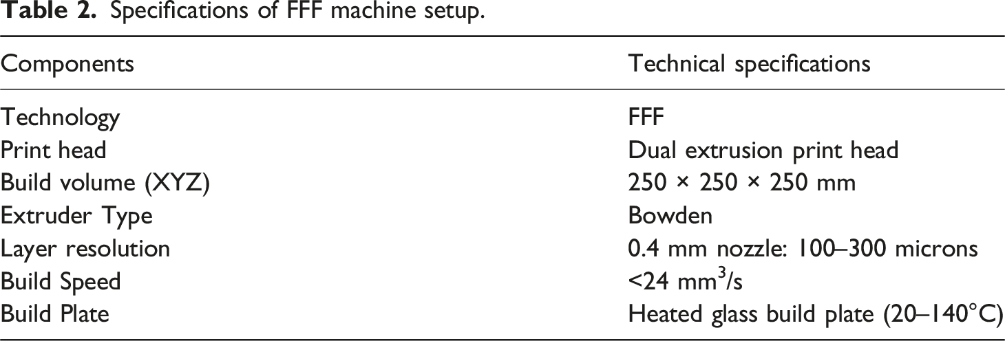
In the 3D printing machine, the dual extrusion print head was installed properly, and the build volume was set to 250 × 250 × 250 mm. Figure 1 shows the schematic lay out of the 3D printer. CF/PLA filament with a diameter of 1.75 mm was loaded into the Bowden-type extruder. The build plate temperatures were set between 20 and 140°C, as recommended for CF/PLA. Additionally, extrusion parameters, such as layer thickness and build speed, were adjusted to obtain optimal printing quality. Once all settings were completed, the printing process was initiated, allowing the 3D printer to deposit successive layers of CF/PLA material. After completing the printing of CF/PLA samples, the samples were removed from the build plate and subjected to post-processing steps to achieve the desired final product. Schematic Layout of FFF printer setup.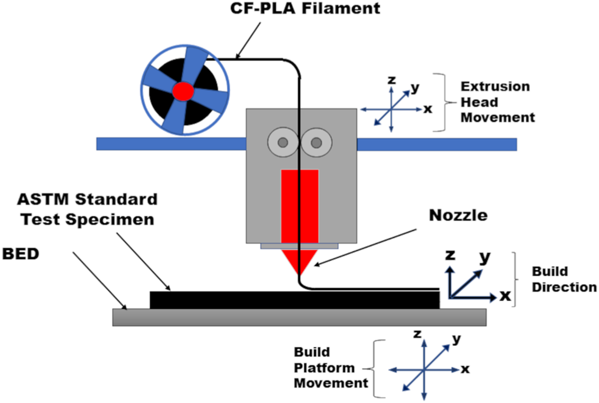
Concerning the machine, a FFF machine was utilized, equipped with dual extrusion technology. This machine’s print head employed a Bowden-type extruder, enabling precise printing of CF/PLA samples.
Piezoelectric sensor
Physical properties 16 of selected piezoelectric sensors/actuators.
Piezoelectric sensor. 28
Structural geometry of sensor and actuator model
When pressure is applied piezoelectric materials deform in response to an applied voltage. 29 When deformed, piezoelectric materials generate a voltage. This sensor module involves only the Young’s modulus E and the appropriate piezoelectric coefficient e_31 as physical properties.
Equation (1) depicts the constitutive Law for the piezoelectric sensor model.
Fundamental beam theory is expressed by the equation (2)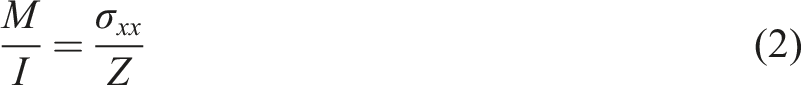
Equation (3) shows the change in momentum caused by the electric field.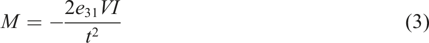
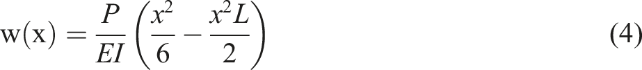
At x=L, equation (5) shows how much the tip moves because of mechanical and electrical load.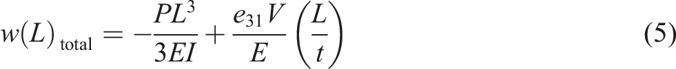
E: Electric field components (N/C)
V: Voltage (v)
M: Moment (N.m)
I: Area moment of inertia of the cross-section (m4),
Z: Modulus
P: External load (N)
E: Young’s modulus (GPa)
Figure 3 depicts a schematic representation of the piezoelectric actuator model. Schematic representation of actuator model.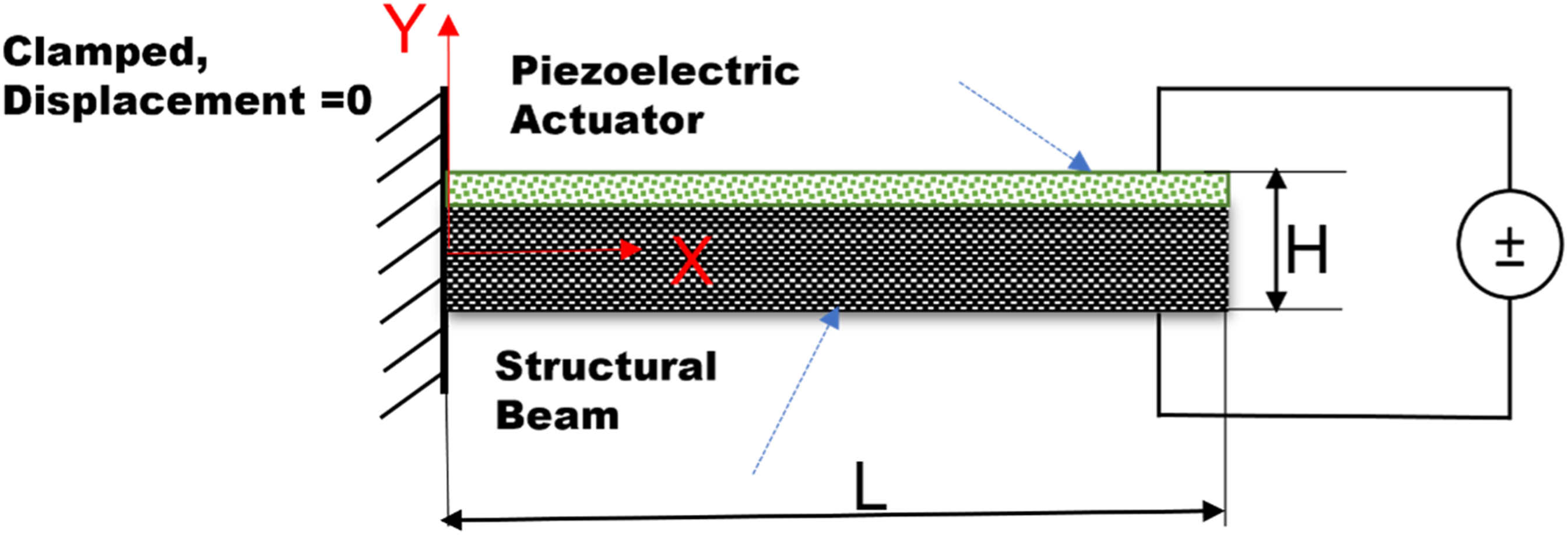
Material characterization
Tensile properties of the CF/PLA samples were tested using an Instron universal testing machine equipped with a 50 KN load cell and a cross-head speed of 2 mm/s. The tensile test was carried out in accordance with ASTM D638
30
(tensile test) and ASTM D732
31
(shear test). A total of 5 samples were tested, and their average values were reported. Figure 4 shows the tensile and shear test samples. (a) Tensile samples and (b) Shear sample.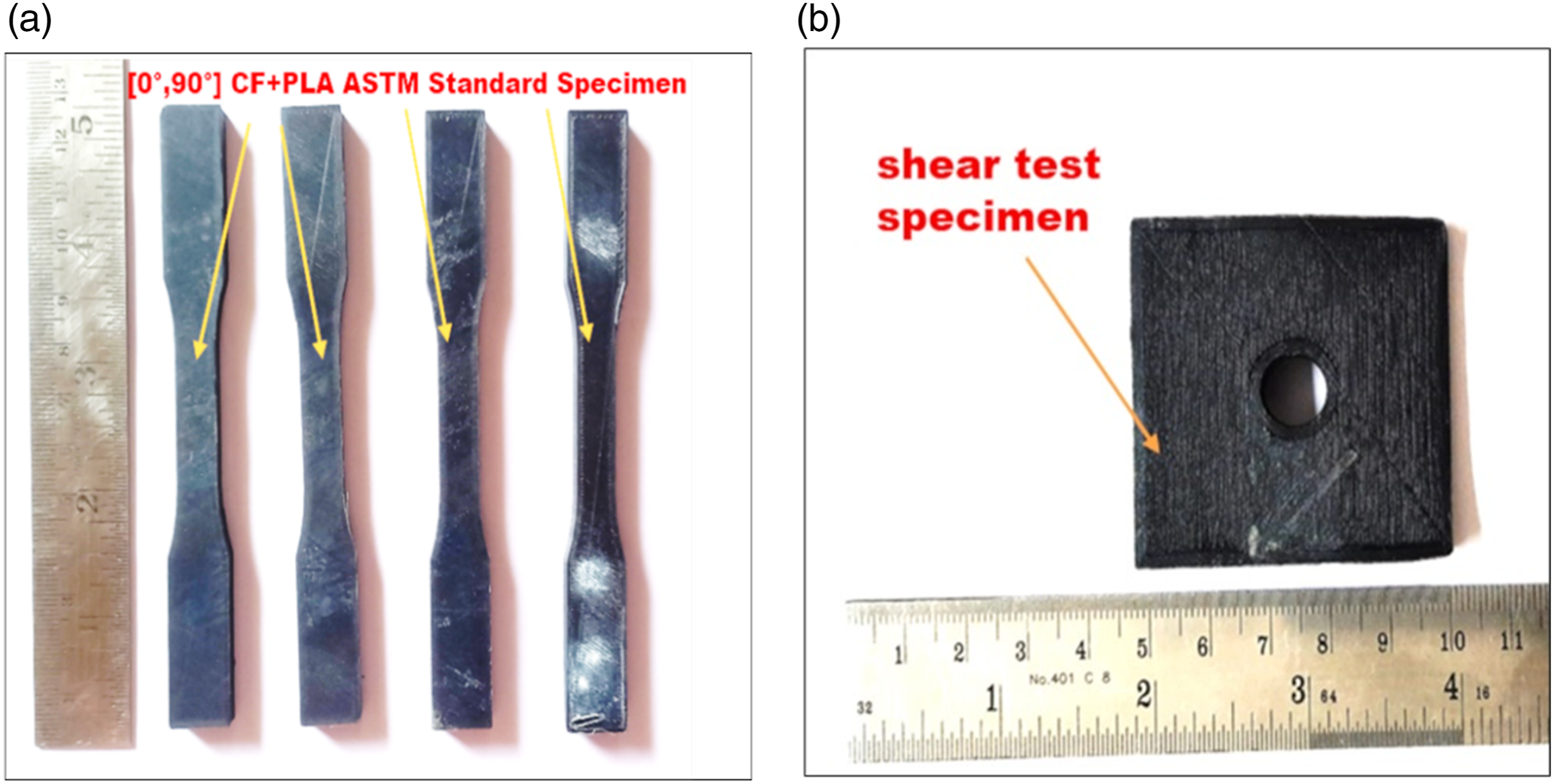
Results and discussion
Mechanical properties
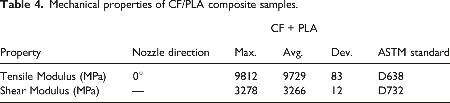
Mechanical properties of CF/PLA composite samples.
Printing parameters.
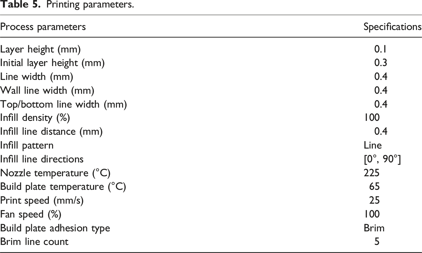
Table 5 provides values of infill density (100%) and infill distance (0.4 mm). The 100% represents a fully dense structure, providing maximum reinforcement using CF. Additionally, 0.4 mm ensures that the CF is distributed evenly within the fabricated samples.34,35
A nozzle temperature of 225°C was used within the recommended range for the PLA matrix. Higher temperatures could facilitate adhesion between the matrix and CF. Furthermore, a build temperature of 65°C helped prevent warping and ensured better layer adhesion in the composite samples.36,37 All composite samples were fabricated using a moderate print speed of 25 mm/s. This speed allowed for proper material deposition in the FDM machine and cooling. Faster speeds could compromise adhesion between each layer and the overall quality of the fabricated samples. In addition, a fan speed of 100% helped promote good layer bonding and reduced deformation. These factors were significant in maintaining the structural integrity of the fabricated composite samples.38,39
The obtained tensile modulus (9812 MPa), shear modulus (3278 MPa), and tensile stress (∼55 MPa) show that the combination of printing parameters (refer to Table 4) resulted in a good bond between the layers and enhanced mechanical properties. These observed properties, such as tensile stress, tensile modulus, and shear modulus, were ascribed to the reinforcing effect of CF, which provided stiffness and strength to the PLA matrix. Figure 5(a) and (b) shows the tensile tested samples and stress strain plot of CF/PLA. (a) Tensile tested samples and (b) Tensile stress-strain diagram.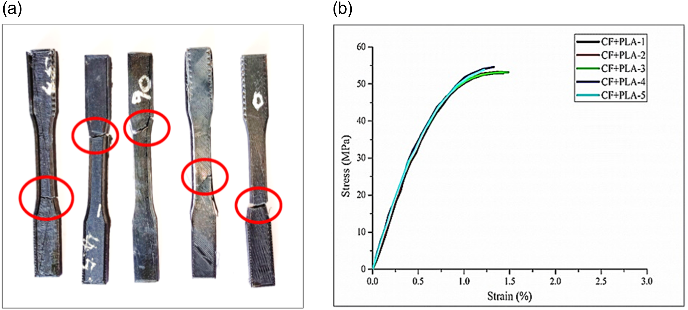
FEA using MATLAB® PDE tool
Application of modeling/FEA analysis
The Finite Element Method and MATLAB® PDE tool significantly examined the behaviour and optimised the performance of CF/PLA samples and piezo-actuated 3D printed samples. The FEM is used to simulate how the complex structures would respond due to varying loading conditions and boundary conditions. These would allow for an analysis of CF/PLA by considering many factors: material properties, geometry and loading conditions. Besides, the MATLAB® PDE could extend the analysis by adding equations enabling the examination of the actuator model for the 3D printed samples, which involves integrating piezoelectric elements.
Mathematical model of piezoelectric actuator
The piezoelectric model examines the relationship between the mechanical and electrical behaviors of the CF/PLA samples. Equation (6) helps in linking the stress tensor and externally applied forces. The equation (7) examines the electrostatic nature by relating the electric displacement vector to charge density. By adding the equations (6)–(8) is formed.
Additionally, constitutive equations (equation (9)) express stress, electric displacement, strain, and electric field in terms of the material’s properties, especially tailored for an orthotropic piezoelectric material under plane stress conditions.
The equilibrium equations describe the solid’s elastic behaviour
Gauss’s Law describes the electrostatic behaviour of a solid
This system combines the two PDE systems such as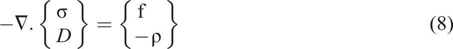
The equation can be written as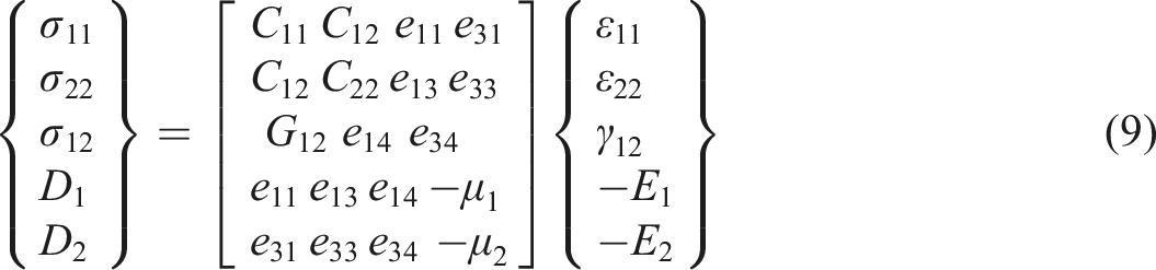
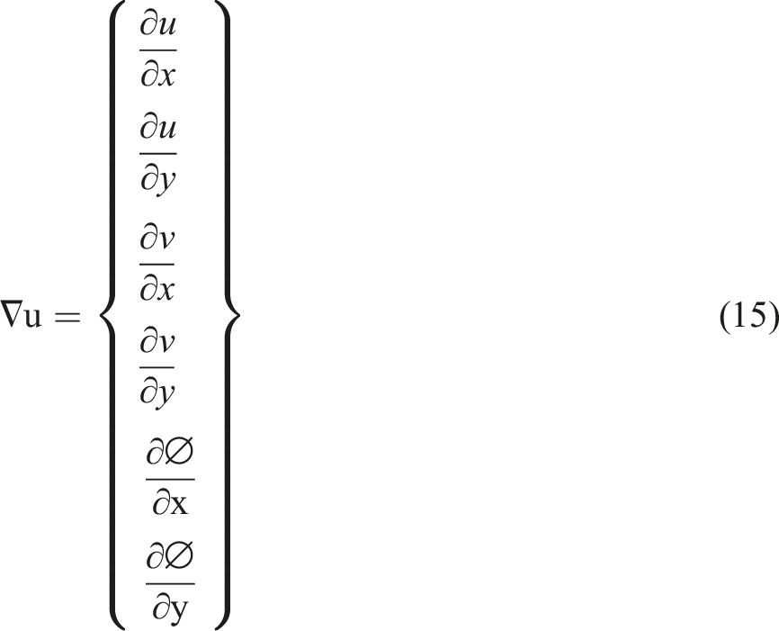
The strain vector, expressed in terms of the x-displacement (u) and y-displacement (v), is provided in equation (10).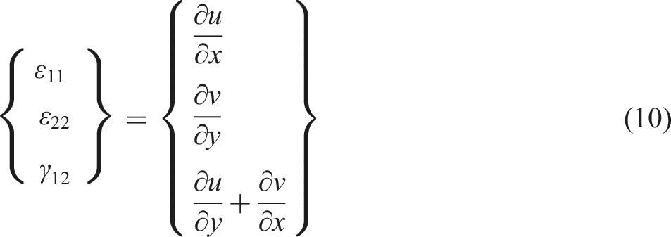
Equation (12) necessitates a vector representation of the elliptic equation.
Or, equation (13) requires a tensor representation.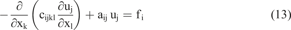
The system vector “u” for a 2-D piezoelectric system is given by equation (14).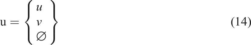
σ: Stress (N/m2)
D: Electric charge density displacement components (c/m2)
ε: Electric permittivity (F/m),
e: Piezoelectric coupling coefficient for stress change form
μ: Primitivity matrix
σ_1: Maximum principal Stress (N/m2)
σ_2: Minimum principal Stress (N/m2)
τ: 12 Shear stress N/m2
In this case, the coefficient ‘c’ is a tensor. It can be represented by a 3-by-3 matrix composed of 2-by-2 blocks. The PDEs toolbox employs FEA to solve structural mechanics and generic PDEs. It can also import 2D and 3D geometries from STL and mesh files. Meshes with triangular and tetrahedral shapes are created. This toolbox’s ability to solve PDEs using the finite element technique and then examine and analyze the results.
The FEM and the MATLAB® PDE code were used to study the CF/PLA beam structure and the piezo under the FFF 3D printed beam (Actuation Model) structure.
Piezo-bonded CF/PLA composite samples
Piezoelectric actuator deflection is calculated using coupled PDEs with deflection and voltage (V) as dependent variables. To solve these equations and analyze the piezoelectric actuator, MATLAB® PDE Toolbox was utilized. A detailed description of the MATLAB® code algorithm is present in the Appendix where algorithms 1 to 4 were used.
Piezoelectric actuator (cantilever beam) model
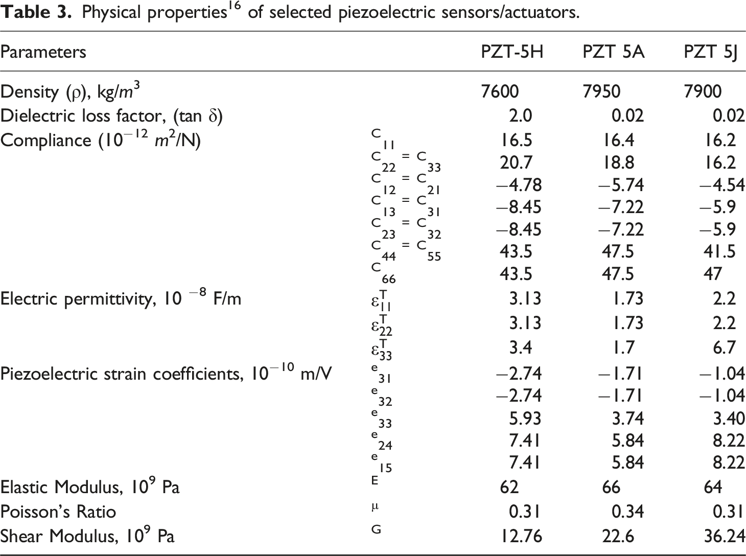
A piezoelectric actuator 40 model composed of PZT-5H, PZT-5A and PZT-5J (Table 3) material is chosen in this part. Using the PDE, the constraint of zero displacements on the left side of the cantilever beam was evaluated. The electrical load was applied to the right end of the embedded sensor model, and the resulting tip deflection was plotted.
Geometry and material
Utilizing the PDE toolbox, the geometry of the cantilever beam was initially built. Due to its function as an actuator, the beam’s shape consists of two layers (refer to Figure 6). A thermoplastic substance was applied to the beam, and Table 3 provides details on material qualities and coefficient specifications. The cantilever has dimensions of 250 mm in length and 25 mm in width. The actuator’s linear elastic behavior involves three components, and a two-layer shape was formed using two rectangles. The MATLAB® algorithm for geometry and material is outlined in Appendix - Algorithms 1 & 2. Finite element model.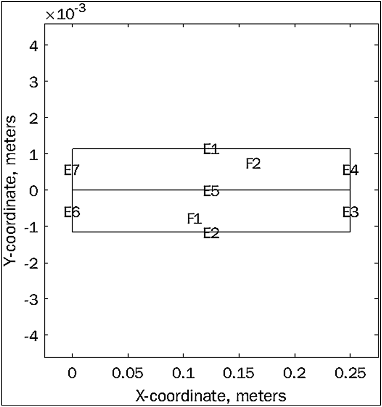
Boundary conditions
The cantilever beam was clamped at the left end for mechanical boundary conditions (clamped displacement = 0 V). An electrical voltage was applied across the positive electrode along the beam thickness to determine electrical boundary conditions, and an in-plane displacement was monitored along its length.
The bending beam model is finely meshed with a global mesh size of 0.0005 m. The finite element model employs a mesh type consisting of four-node, 12-degree-of-freedom quadrilateral plate bending elements, with one electrical degree of freedom. For structural analysis, a 2D solid element is used, while a scalar electric potential element is used for the electric field. The MATLAB® algorithm detailing the definition of boundary conditions is provided in Appendix-Algorithm 3.
Finite Element Simulation Result
The CF/PLA samples embedded with three distinct piezoelectric actuators: PZT-5H, PZT-5J, and PZT-5A material, were simulated using finite elements, applying an external actuating voltage. 41 The analysis was conducted based on the input material properties of CF/PLA and the selected piezoelectric actuators as outlined in Table 3.
The electric field induces a repulsion between the long-chain molecules of the piezoelectric material. The CF/PLA samples were fabricated using an FFF machine with a piezo actuator. The electrical field was applied to the sensor located at the at the right end of the model. An actuator, activated by a function generator at a specific frequency and voltage 20 caused base excitation. The tip deflection 42 was measured using NI myDAQ experimental equipment.
The MATLAB® code was developed for geometry and tip deflection in the X and Y directions. Additionally, electric potential data were computed and compared for the selected piezoelectric sensor. The finite element and analytical results for PZT-5A (Figure 7(a)–(c)), PZT-5H (Figure 8(a)–(c)), and PZT-5J (Figure 9(a)–(c)) were graphically plotted using outputs from the PDE tool. PZT-5 A embedded CF+PLA x,y directional deflection and electric potential. PZT-5 A embedded CF+PLA x,y directional deflection and electric potential. PZT-5 J embedded CF+PLA x,y directional deflection and electric potential.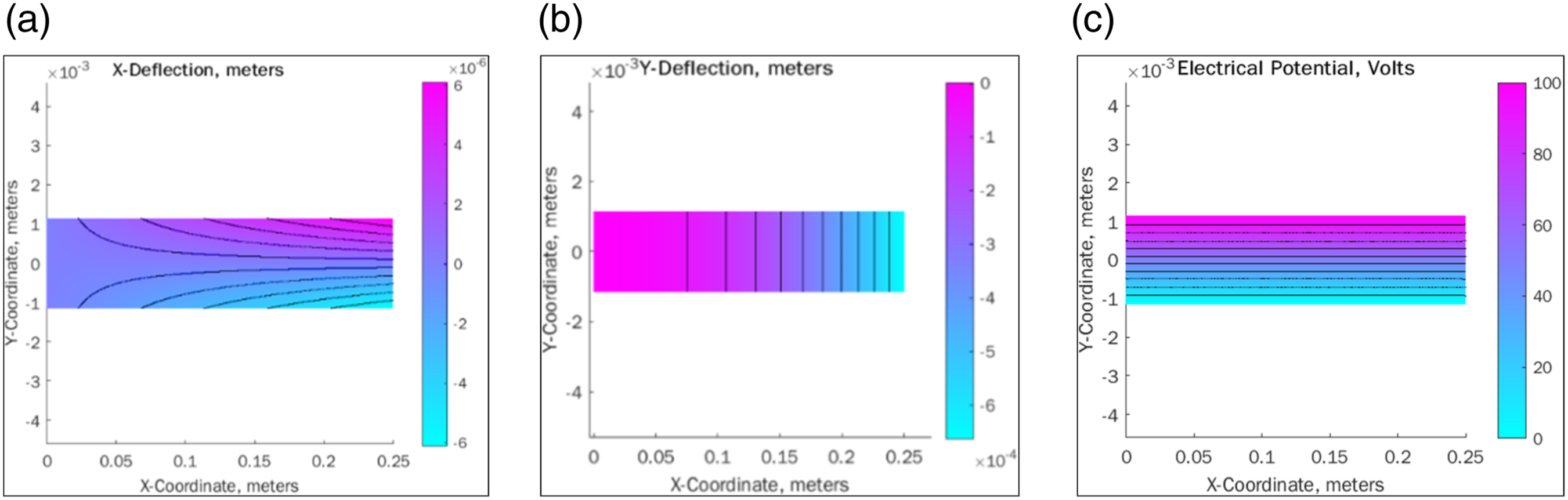
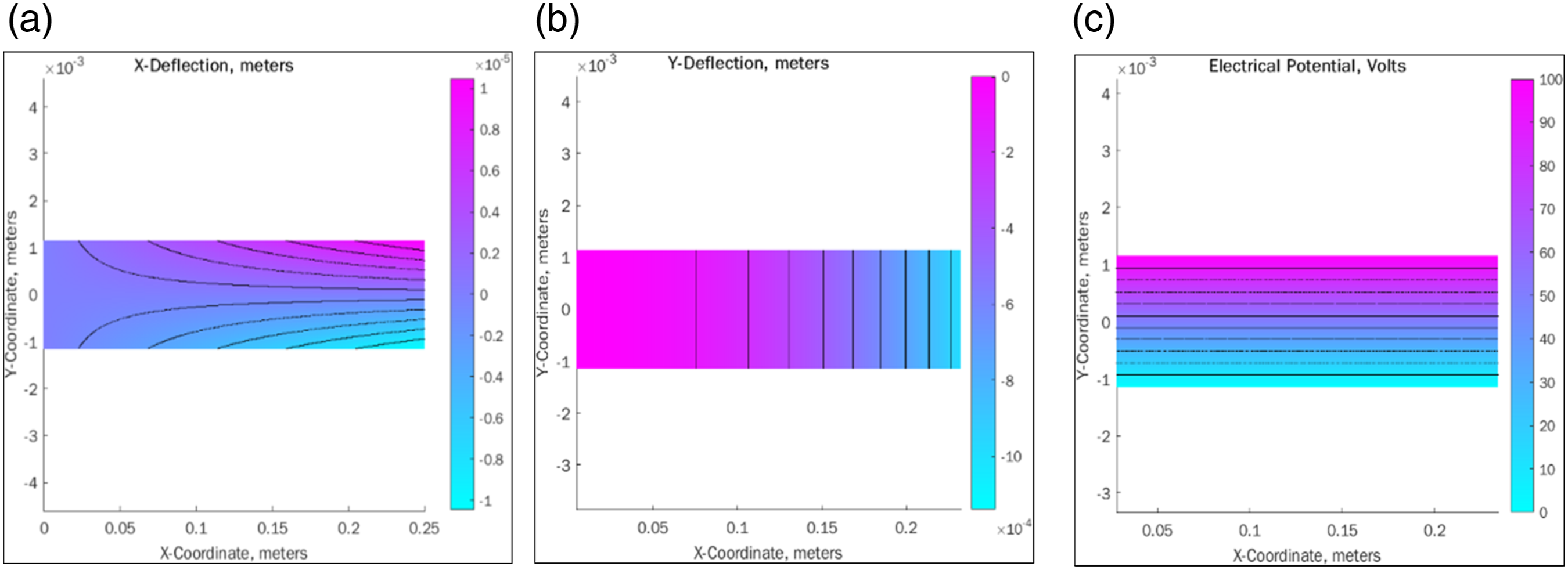
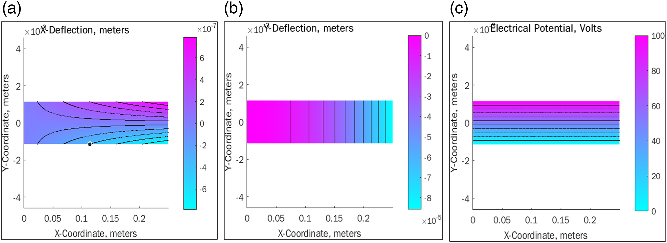
The generated finite element tip deflection for the PZT-5J, PZT-5H, and PZT-5A embedded CF/PLA composite material is 0.0000065765 m, 0.000005197 m, and 0.0000076328 m, respectively. The calculated analytical tip deflection for the same materials is 0.0000055953 m, 0.0000041519 m, and 0.0000065218 m. Details of the MATLAB® algorithm used to determine tip deflection can be found in Appendix.
Experimental investigation
Piezo-enabled composite strain measurement
The integration of PZT 5H, PZT 5A, and ceramic actuators into the CF/PLA composite samples, followed by the ASTM standard dimensions, presented challenges, particularly concerning electrical insulation. Subsequently overcoming these challenges, the process involved to affix the actuators such as PZT 5H, PZT 5A, and PZT 5J onto the cantilever beam sample. Different techniques as well as bonding approaches were used to place the PZT elements in the CF/PLA sample and ensured the effective electrical insulation. These steps aimed to improve the material’s strength while utilizing the piezoelectric properties of the embedded PZT elements.
LABVIEW
43
facilitated the real-time gathering and display of output signals from the piezoelectric sensors, using virtual instrumentation. Figure 10 shows the real-time data collection hardware system. The piezoelectric fibre composite sensors, developed with PZT, undergone a conversion of mV to volts with an amplification factor of 1000 for piezo sensors. The piezoelectric efficiency was measured using a two-mode system, where the load was proportional to the supplied voltage, contingent on geometrical parameters.
44
Schematic representation of experiments using piezo-enabled beam structure.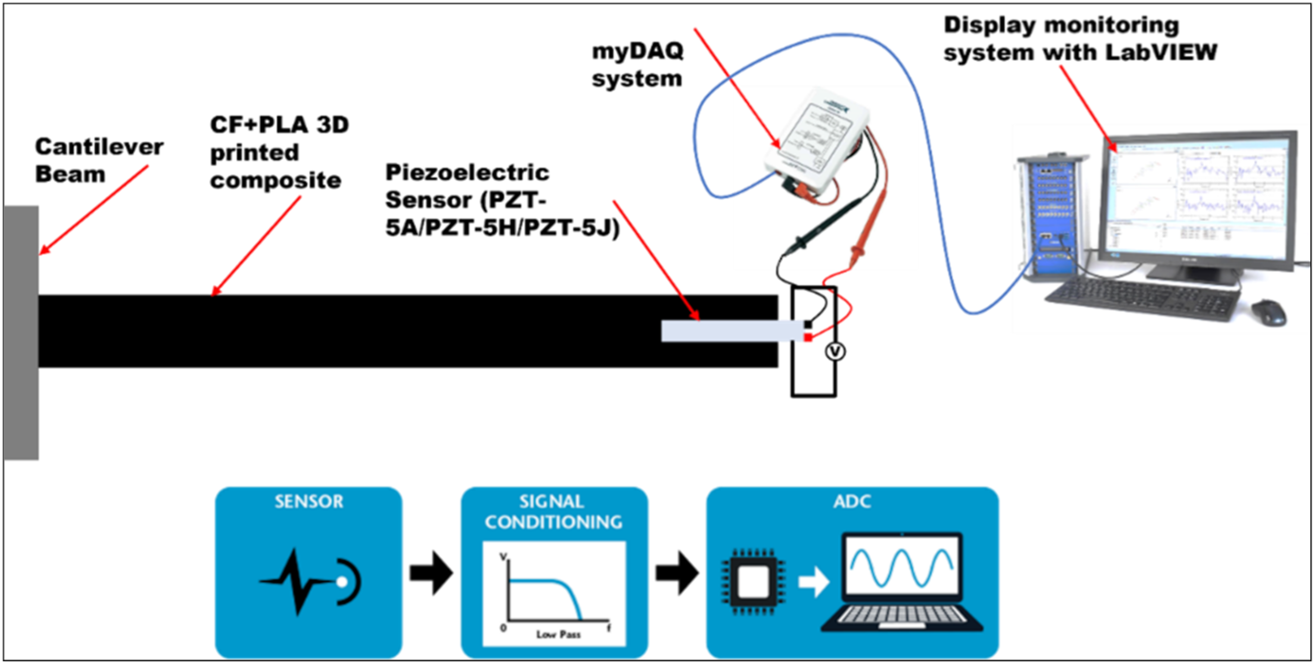
Embedded the PZT ceramic lamination into the CF/PLA sample, in adherence to ASTM standards, presented specific challenges related to the electrical insulation. It’s crucial to address these challenges to integrate with the CF/PLA composites. During the composite curing cycle, embedded sensors were at risk of short-circuiting. 45 The insulating layers were employed to prevent contact between the anode and cathode of the PZT and CF during the curing cycle.
The integrity of the PZT was qualitatively examined through measurements of capacitance and resistance. Besides, this work explored the embedding of PZT sensors/actuators in thicker composites, aimed to create in-situ condition monitoring techniques that enhanced the operational safety of composite structures utilizing the PZT sensors.
Experimental test results
Piezoelectric smart actuating materials integrated into a laminated composite act as the sensing elements. A 3D-printed hybrid structure was checked for active damage using embedded piezoelectric materials linked to the myDAQ and LabVIEW® spectrum 46 monitoring instruments. It is also possible to detect ongoing structural degradation with this piezo smart structure technology.
The numerical results may also be used as a guide for deciding on the coating layers’ material properties and thickness. The relationship between maximum mechanical displacement and variables such as applied electric potential, composite thickness, volume per cent, and composite height ratio was also investigated. Due to the inclusion of piezoelectric materials, a linked model with mechanical (displacements) and electrical (charges at electrodes) degrees of freedom was developed.
A method was created for incorporating piezoceramic sensor
47
and actuator patches into 3D-printed CF/PLA composite structures to make active composite panels with precise positioning. The performance of the smart CF/PLA composite was then tested in the lab. A method for integrating piezoceramic sensor and actuator patches embedded into 3D printed CF/PLA composite structures to create active composite panels with simultaneous precision positioning was developed, and the performance of the smart CF/PLA composite was determined experimentally. An embedding technique is possible in the FFF technique with an appropriate CAD model and process parameter technique. The myDAQ system’s NI instrument includes a digital oscilloscope mode, a function generator, an oscillator circuit, and an impedance analyzer
48
that senses data from the piezoelectric actuator. The cantilever beam’s tip deflection was measured in a 50V electric field during this phase. The FEM predicted results were compared to experimental data conceptually and experimentally, as shown in Figure 11. Correlation of FEM, Analytical and Experimental results.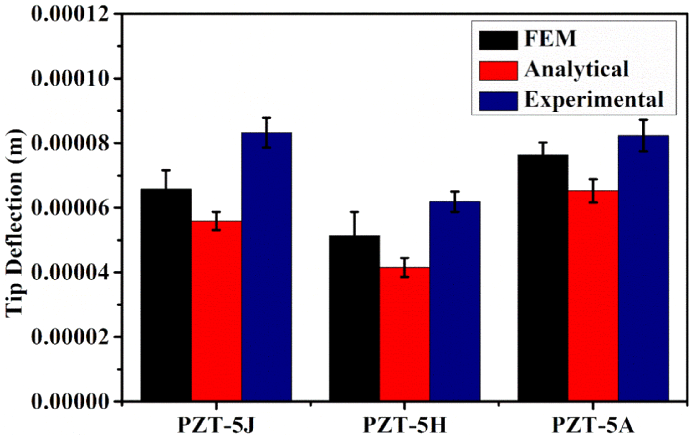
As expected, the piezoelectric actuator’s tip deflection rises in the negative y direction. The results are in line with one another. The experimental tip deflection with the corresponding actuator type was observed as 0.0000083249 m for PZT-5J, 0.0000061873 m for PZT-5H, and 0.0000082358 m for PZT-5A. The FEM and theoretical conclusions are also confirmed by creating a measuring setup.
The experimental validation of the parameters, under consideration focuses on confirming and refining the characteristics of tip deflection in actuators. Specifically, this validation is done for actuators embedded in materials made of CF/PLA using PZT-5J, PZT-5H and PZT-5A. The results obtained through FEM simulations and theoretical calculations consistently show an increase in tip deflection towards the y direction. The experimental findings support the conclusions drawn from FEM simulations and theoretical analysis; thus, reinforcing the accuracy of predictions. Comparing calculated and experimentally observed tip deflections provides insights into the performance of actuators aiding in optimizing design parameters for better functionality and reliability. In summary this comprehensive approach that integrates analysis, theoretical calculations and experimental validation contributes to an understanding and improvement of tip deflection behavior, in studied piezoelectric actuators and composite materials.
Error estimation and accuracy analysis in conformity testing for quality
Characterization with cross-literature validation
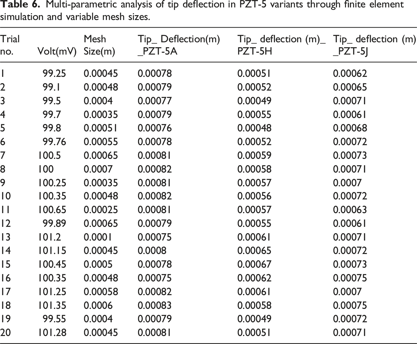
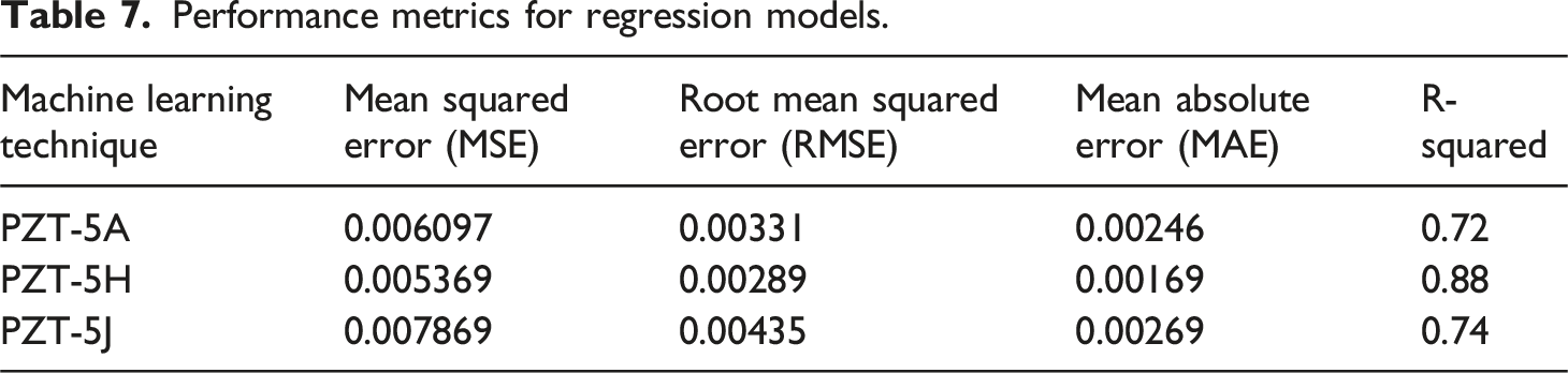
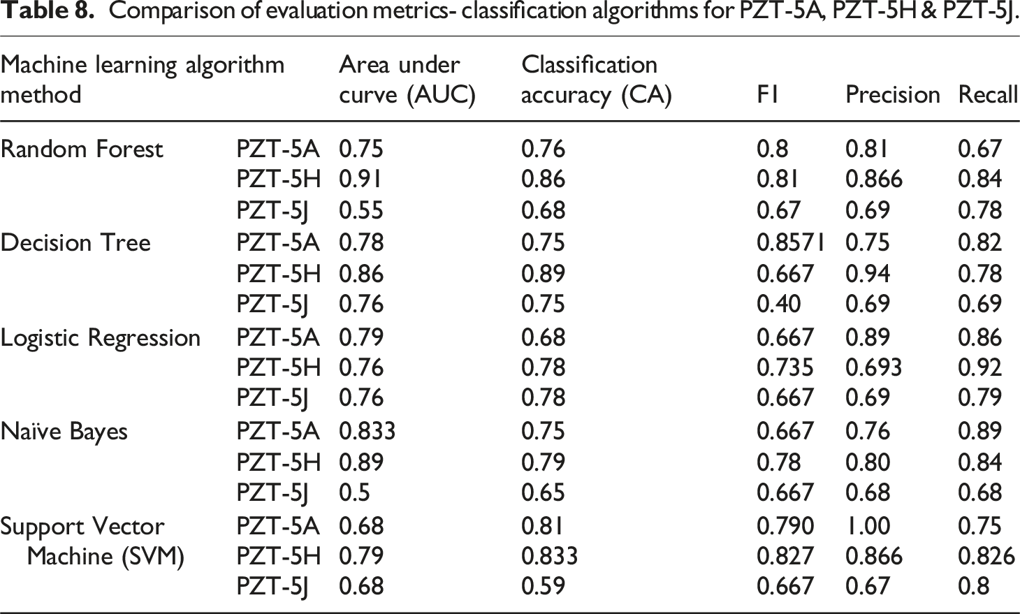
This research work primarily focuses on addressing the challenges that arise when analyzing errors and accuracy in the context of conforming test results and determining quality characteristics based on parameters. To navigate through these complexities, a method grounded in machine learning algorithms was used. 49 Systematically applied chosen algorithms, like Random Forest, Decision Tree, Logistic Regression, Naïve Bayes and Support Vector Machine (SVM) to three variants of PZT 5; PZT 5A, PZT 5H and PZT 5J. By using evaluation metrics such as Area Under Curve (AUC), Classification Accuracy (CA), F1 score, Precision, Recall; along with regression analysis metrics like Mean Squared Error (MSE), Root Mean Squared Error (RMSE), Mean Absolute Error (MAE) and R Squared 50 ; Created a comprehensive framework to assess the performance of these machine learning techniques. The main objective is to improve the reliability of the analysis and validate the conformity test results by comparing them with existing literature. This will contribute to an understanding of tip deflection, 51 in variants of PZT 5 through finite element simulation and variable mesh sizes.
Multi-parametric analysis of tip deflection in PZT-5 variants through finite element simulation and variable mesh sizes.
Performance metrics for regression models.
Comparison of evaluation metrics- classification algorithms for PZT-5A, PZT-5H & PZT-5J.
Conclusion
This research work aimed to correlate the experimental results of piezo-embedded CF/PLA composites with mathematical and numerical modelling approaches. The significant findings of this work are summarized below. • The optimised printing parameters, such as smaller layer heights line widths, helped improve the interfacial adhesion in the CF/PLA composites. • A nozzle temperature of 225°C and a building temperature of 65°C were maintained to prevent warping and ensure better layer adhesion in the fabricated composite samples. Besides, printing speed (25 mm/sec) and fan speed (100%) significantly achieved optimal layer bonding and reduced deformation. • All these optimized parameters resulted in significant mechanical properties with a tensile modulus of 9812 MPa, shear modulus of 3278 MPa, and tensile stress of approximately 55 MPa. • The developed mathematical model was explained the relationship in the CF/PLA samples using solid-state and electrostatic behaviours. FEM and MATLAB® PDE codes were used to examine the CF/PLA samples and piezo-actuated FFF 3D printed beam (actuation model) structure. • The FEM employed a mesh type consisting of four-node, 12-degree-of-freedom quadrilateral plate bending elements with one electrical degree of freedom. • From the experimental observation of the tip deflection in actuators embedded in CF/PLA composites used PZT 5J, PZT 5H, and PZT 5A. It was observed that a consistent increase in the tip deflection towards the y-direction in both theoretical and experimental findings. • Machine learning algorithms such as Random Forest, Decision Tree, Logistic Regression, Naïve Bayes, and SVM were used to analyze the errors and accuracy in confirming test results. Besides, these were used utilized to determine the quality characteristics based on the parameters. • The PZT 5H has consistently exhibited more accurate tip deflection values than PZT 5A and PZT 5J.
Future direction and applications
The investigation primarily focused on studying a group of actuators. However, it would be beneficial to explore materials and different actuator configurations to gain a comprehensive understanding. Additionally, the study mainly looked at the aspects. Further research could delve into optimizing energy harvesting efficiency and exploring how these actuators can be applied in real world scenarios. It’s important to note that the findings are based on simulations and experiments conducted under controlled conditions. Therefore, when applying these models, in situations there may be challenges. Future work could involve conducting scalability studies assessing long term durability and considering real world implementation factors to ensure that the proposed piezo embedded CF+PLA composite is feasible and robust, in environments and applications.
The findings from this work indicate that the developed composite material can be suited for precision engineering, aerospace components and other industries where lightweight strong materials are crucial. Besides, the ability to accurately control and anticipate tip deflections highlights the potential of this composite in applications that demand high performance materials with properties. Considering its compatibility with embedded PZT elements there may be opportunities to use this material in structures like sensors or actuators, for monitoring health or controlling vibration.
Limitations
One drawback of this research is that the mathematical model proposed might have made simplifications or assumptions that don’t fully capture the behaviors of the piezo embedded CF/PLA composites. Moreover the study specifically focuses on a set of optimized printing parameters and variations, in printing conditions could potentially affect how applicable the findings are. It’s worth noting that the machine learning algorithms used for analysis might have limitations when it comes to dealing with relationships within the data. Lastly the study primarily relies on a range of materials (PZT 5J, PZT 5H and PZT 5A) which restricts its broader applicability, to other piezoelectric materials.
Footnotes
Acknowledgements
This research budget was allocated by National Science, Research and Innovation Fund (NSRF), and King Mongkut’s University of Technology North Bangkok (Project no. KMUTNB-FF-67-A-01).
Declaration of conflicting interests
The author(s) declared no potential conflicts of interest with respect to the research, authorship, and/or publication of this article.
Funding
The author(s) received no financial support for the research, authorship, and/or publication of this article.
Appendix
L
Beam Length in meter
H
Height of the Beam in meter
1)
model
Createpde(3)/*Matlab library -Partial Differential Equation Tool box */
2)
H2
H/2
3)
TopLayer
InitializeTopLayer (H2)/* [3 4 0 L L 0 0 0 H2 H2] */
4)
BottomLayer
InitializeBottomLayer (H2)/* [3 4 0 L L 0 -H2 -H2 0 0] */
5)
gdm
find GeometryDescriptionMatrix (top layer, bottom layer);
6)
edge
Compute Geometrical Object Edge (gdm)/* decsg – decomposes the geometry description – matlab library */
7)
PlotObject (model, edge)
return model
E
Elastic Modulu, N/m2
NU
Poisson’s ratio
G
ShearModulus, N/m2
d31
Piezoelectric strain coefficient
d33
Piezoelectric strain coefficient
rp
Relative Permittivity
pfs
Permittivity free space
1)
C11
E/(1-NU2)
2)
C11
NU*C11
3)
c2d
[C11 C12 0; C12 C11 0; 0 0 G]
4)
pzeD
[0 d31; 0 d33; 0 0]
/* Piezoelectric stress coefficients */
5)
pzeE
c2d * pzeD
6)
constant_stress = [rp 0; 0 rp]* pfs
7)
constant_strain = const_stress – pzeD’ * pzeE;
/* Initialize Dielectric Matrix */
8)
c11 = [c2d(1,1) c2d(1,3) c2d(3,3)]
9)
c12 = [c2d(1,3) c2d(1,2); c2d(3,3) c2d(2,3)]
10)
c22 = [c2d(3,3) c2d(2,3) c2d(2,2)]
11)
c13 = [pzeE(1,1) pzeE(1,2); pzeE(3,1) pzeE(3,2)]
12)
c23 = [pzeE(3,1) pzeE(3,2); pzeE(2,1) pzeE(2,2)]
13)
c33 = [D_const_strain(1,1) D_const_strain(2,1) D_const_strain(2,2)]
14)
ctop = [c11(:); c12(:); c22(:); -c13(:); -c23(:); -c33(:)]
15)
cbot = [c11(:); c12(:); c22(:); c13(:); c23(:); -c33(:)]
return C
C
/* Apply Boundary Conditions */
1)
model
ApplyTop (model, voltTop, C)
2)
model
ApplyBottom (model, voltBottom, C)
3)
model
ApplyLeft (model, ClampLeft, C)
4)
mesh
generateMesh (model, C)
5)
Result
solvepde (model,C)/*solvepde –MATLAB® library function */
6)
rs
result.NodalSolution
7)
FiniteElementTipDeflection
min(rs(:,2))
return FiniteElementTipDeflection
d31 - Piezoelectric strain coefficient
H - Height of the Beam in m
1)
H2
H/2
2)
tipDeflection
−3*d31*100*L2/(8*H22)
return AnalyticalTipDeflection