
Abstract
Additive Manufacturing (AM) techniques, particularly Fused Filament Fabrication (FFF), have revolutionized prototyping and low-volume production. Improving the tensile properties of FFF-printed parts is a primary objective to elevate their functional utility. This study aimed to investigate the effects of annealing time (ATM), annealing temperature (ATP), and nozzle diameter (ND) on the tensile strength (TS) of two commonly used printing materials: Polyethylene Terephthalate Glycol (PETG) and PETG reinforced with carbon fibre (PETG-CF). Samples with varying ND (0.4 mm, 0.6 mm, and 0.8 mm) underwent annealing at ATP of 80°C and 100°C for ATM of 60 min and 120 min, respectively. Subsequent tensile tests were meticulously conducted, and regression models were employed to comprehensively analyse the influence of these control factors on TS. The findings from the tensile tests on annealed specimens revealed substantial improvements in TS for both PETG and PETG-CF materials. Statistical analysis, Taguchi method (TM), and response surface methodology (RSM) indicated that ND exerted a more pronounced impact on TS compared to ATM and ATP. By identifying the optimal control factor combinations for each material, the study pinpointed that the best TS was achieved at 0.8 mm ND, 120 minutes ATM, and 100°C ATP for PETG-CF. The remarkable enhancement in tensile properties for annealed FFF-printed parts underscores the potential of PETG-CF to replace structural metallic components in critical applications within the automotive and aeronautical industries.
Keywords
Introduction
AM has emerged as a revolutionary technology with diverse applications in industries such as aerospace, defence, automotive, communications, and medical fields.1,2 Its ability to produce complex and customized components in small quantities makes it highly valuable in various sectors. Compared to traditional manufacturing methods, AM offers numerous advantages, particularly in functional part production and efficient spare parts supply through on-demand manufacturing and repair processes. One of the key advantages of AM is its layer-by-layer approach, where objects are created based on a 3D computer-aided design (CAD) model. A computer controls the printer head’s movement and regulates the flow of melted filament. The molten filament is deposited on a build platform or previously printed layers following a predefined path. Rapid cooling and solidification of the extruded filament led to the formation of a solid layer. This technology enables the production of highly intricate parts with complex geometries, eliminating the need for specialized tools or fixtures and minimizing waste generation.
Among various AM technologies, FFF3–5 as shown in Figure 1 stands out due to its cost-effectiveness, user-friendliness, minimal waste production, and ability to print intricate structures. FFF uses different filaments, such as Poly Lactic Acid (PLA),6–12 Acrylonitrile Butadiene Styrene (ABS),
13
PETG,14–16 Nylon, and Polycarbonate, each having unique properties suitable for specific AM applications. PETG, a modified version of Polyethylene Terephthalate (PET), has gained popularity in AM due to its affordability and higher strength compared to other polymer filaments.17,18 It is widely used and ranks third in usage after ABS and PLA. Researchers have studied the behaviour of PETG and PLA during annealing, a post-processing step. Annealing at higher temperatures than the glass transition temperature allows PETG to recover its interlayer TS, while PLA regains its interlayer TS when annealed at temperatures between its glass transition temperature and cold-crystallization temperature. Schematic view of FFF Technology.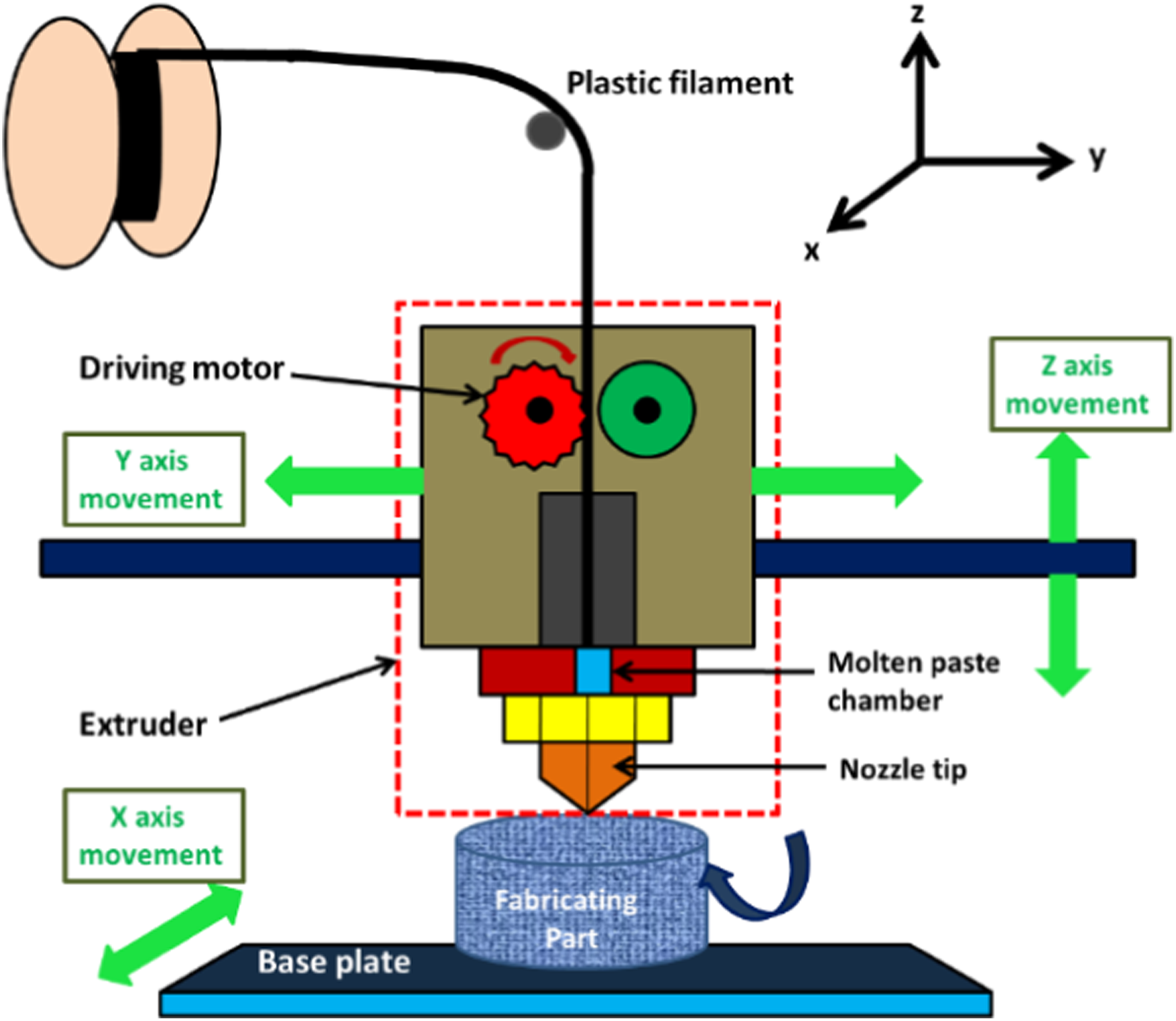
To further enhance the mechanical and thermal properties of PETG, reinforcement materials such as glass fibre, carbon nanotubes, and CF are commonly used.19–23 These reinforcements create fibre-filled thermoplastic composites, where the fibres provide load support, and the matrix binds and protects them. The advantage of using these fibre-filled filaments is that they can be processed using similar parameters to neat thermoplastic filaments, making them compatible with existing FFF-type 3D printers. 24
During the AM process, several control factors need to be considered, including layer thickness, ND, layer height, infill density, printing speed, infill pattern selection, and raster orientation.15,25–27 Researchers continuously explore methods to enhance FFF part properties, such as mechanical strength, accuracy, and surface roughness, through various post-treatment techniques, printing control factor optimization, material characterization, and material reinforcement.
Heat treatment, traditionally used for metals, is also applied to AM for enhance material properties.28–32 Annealing, a heat treatment method, can significantly improve the material properties of FFF-fabricated objects. By raising the temperature above the glass transition temperature but below the melting point, annealing increases crystallinity and redistributes stress within the material, resulting in improved stiffness, strength, heat deflection temperature, and chemical resistance. However, annealing can cause deformation of the FFF-fabricated object, which can affect its functionality. A study conducted by Akhoundi et al. 33 explored the impact of annealing on the TS of High-Temperature PLA. Their findings indicated that annealing resulted in a noteworthy improvement in TS, raising it from 65.7 MPa to 67.4 MPa. In a separate investigation by Miroslav Pastorek et al., 34 annealing was examined for its ability to enhance the crystallinity of PLA when mixed with 3% wood flour. The annealing process involved subjecting the material to ATP of 100°C for 90 minutes as an additional post-processing step. Moreover, Prajapati et al. 35 delved into the effect of annealing on the heat conductivity of parts fabricated using FFF with ABS. After subjecting the ABS parts to annealing at 135°C for 96 hours, they reported a substantial increase of 150% in heat conductivity.
Additionally, thermal annealing was explored for composite filaments. For instance, the inter-layer tensile characteristics of PETG-CF and PLA was enhanced through post-processing annealing. 19 Furthermore, annealing at 120°C for 8 hours resulted in a crystallinity of 30.2% for PETG. Notably, annealing also exhibited positive effects on older PLA filaments and their composites. The post-processing treatment led to improvements in crystallinity, mechanical properties, and thermal performance of the materials. 36 Moving beyond PLA-based materials, researchers explored the application of annealing to enhance the compressive strength of FFF-fabricated Poly-aryl-ether-ether-ketone (PEEK) cages. PEEK, known for its biocompatibility and high melting temperature of 340°C, was subjected to annealing at 200°C and 300°C. The results indicated a notable increase of 14% in the compressive strength of the 3D-printed PEEK cages. 37
Previous studies have shown that annealing can improve the strength and surface quality of FFF-printed parts, as well as the interlaminar toughness of polymers, surpassing the performance of injection-moulded samples.38–40 The process has demonstrated positive effects on mechanical properties such as flexural and compressive strengths of PLA parts and PETG-based composites reinforced with CF. Research on composites of PLA, ABS, and PETG reinforced with CF has also shown significant improvements in mechanical properties with varying ATPs. However, limited attention has been given to exploring the effects of annealing on the interlayer mechanical properties of FFF-fabricated composites. Examining how ND and annealing affect the strength of PETG and Its composite is a novel approach, and these aspects will help researchers better understand how to tailor the mechanical characteristics of these materials to structural applications.
The input parameters of the FFF process were optimized using various experimental designs, including full factorial design, artificial neural network, 41 bacterium forging method, RSM, and the TM.42–44 Among these, the TM was commonly employed due to its robustness, tolerance, and dimension control. This methodology helped identify the most favourable values of process parameters to optimize the target output. Additionally, RSM was utilized for estimating the effects of different variables and predicting the most important input parameters, offering flexibility in experimental design.
To address these gaps, this study aims to investigate how different FFF control factors, specifically ND, ATP, and ATM, affect the durability and mechanical properties of specimens. The hypothesis is that manipulating these control factors will significantly impact the tensile characteristics of PETG and PETG-CF composites. The study will use high-resolution microscopy to analyse fracture surfaces and understand the failure mechanisms better. Additionally, the outcomes of tensile testing will be compared using statistical techniques such as ANOVA, the TM, and RSM to establish the relationship between TS and variations in control factors.
Materials and methods
Material
The study utilized commercial grade PETG (PETG M300 Plus) in powdered form as the primary material, obtained from Zotrax in Olsztyn, Poland. The PETG has specified characteristics, including a 7.39% stretch at yield, a tensile modulus of 42.50 MPa, a melting point of 240°C, a melt flow index of 22.34 g/10 min, and a glass transition temperature of 78.40°C. PETG-CF filament was created by incorporating 20% by weight of sliced CFs with an estimated length of 60 mm, sourced from 3D Cubic in Surat, Gujarat, as a fine powder.
Methodology
The research followed a systematic approach to prepare and examine both PETG and PETG-CF specimen. PETG-CF was produced by mixing CF granules with PETG granules using mechanized mixing. The combined granules were then dried in a standard oven to remove absorbed moisture. Drying processes varied for pure PETG and CF granules, with pure PETG granules dried for 24 hours at 55°C.
Filaments of 1.75 mm diameter were extruded for each material composition using a Fila Bot EX6 single screw extruder. Filament diameter was measured for quality assurance using a Vernier calliper and the extruder’s in-situ diameter measurement method.
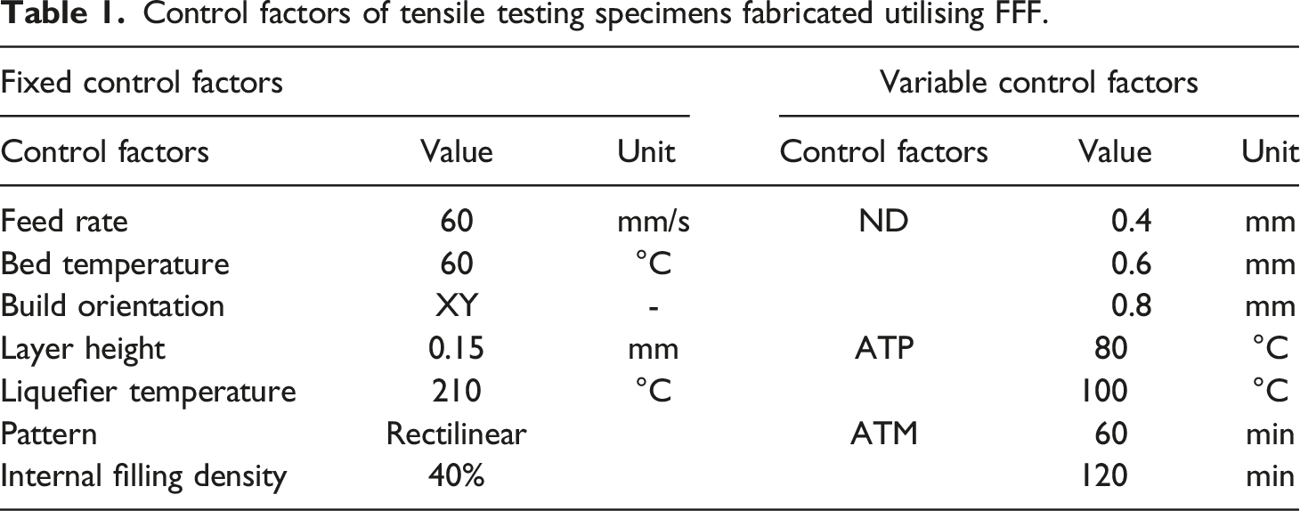
ASTM D638 Type-IV specimens as shown in Figure 2(a) and (b) were fabricated from both PETG and PETG-CF using a FFF printer from 3DCubic. A total of 30 specimens were produced, varying ND, ATP, and ATM. ND was altered between 0.40 mm, 0.60 mm, and 0.80 mm. Two ATM of 60 minutes and 120 minutes, as well as two ATP of 80°C and 100°C, were explored. Specific control factors for the samples, classified as variable and fixed, are provided in Table 1. (a). ASTM D638 Type-IV Specimen, (b) Specimens after tensile testing. Control factors of tensile testing specimens fabricated utilising FFF.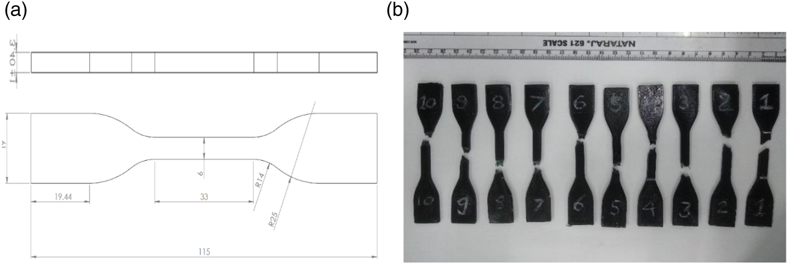
Data of TS for PETG and PETG-CF specimens.
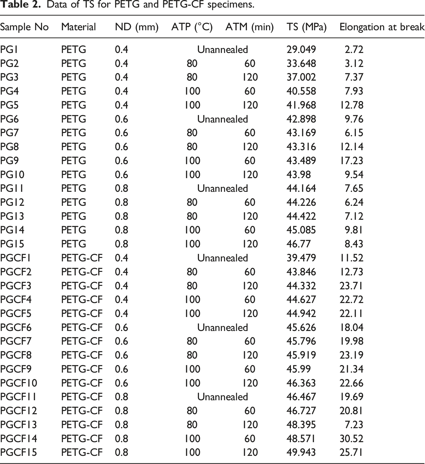
Subsequently, tensile testing was performed on the specimens using a Victor Universal Testing Machine (UTM) following ASTM D638 Type-IV standard specifications. The tensile test results for both PETG and PETG-CF specimens, along with variations in the control factors, were recorded in Table 2. As a component of the microstructural analyses, the fractured edges of the specimens as shown in Figure 2(b) were meticulously examined under a scanning electron microscope (SEM) at various magnifications. The JEOL JSM-IT800 SEM was the instrument employed for this purpose, allowing for high-resolution imaging and detailed inspection of the damaged surfaces resulting from the tensile testing of the specimens, following the ASTM D638 Type-IV standard. During the tensile testing process, some of the specimens experienced collapse or failure, leading to fracture of the material. By scrutinizing these fractured surfaces under the SEM, researchers gained valuable insights into the material’s microstructure and the mechanisms of failure. The SEM images provided a close-up view of the fracture features, such as cracks, voids, and deformation patterns, at different scales.
To analyse the relationship between mechanical behaviour and the varying control factors, statistical techniques such as the TM and RSM with Analysis of Variance (ANOVA) were employed.
Results and Discussion
The study will assess the influence of ND, ATP, and ATM on the materials’ TS. By comprehensively examining the data and employing regression analysis, the research aims to provide valuable insights into optimizing control factors for enhancing the mechanical strength of FFF printed parts, thereby benefiting various industrial applications.
Experimental Investigation
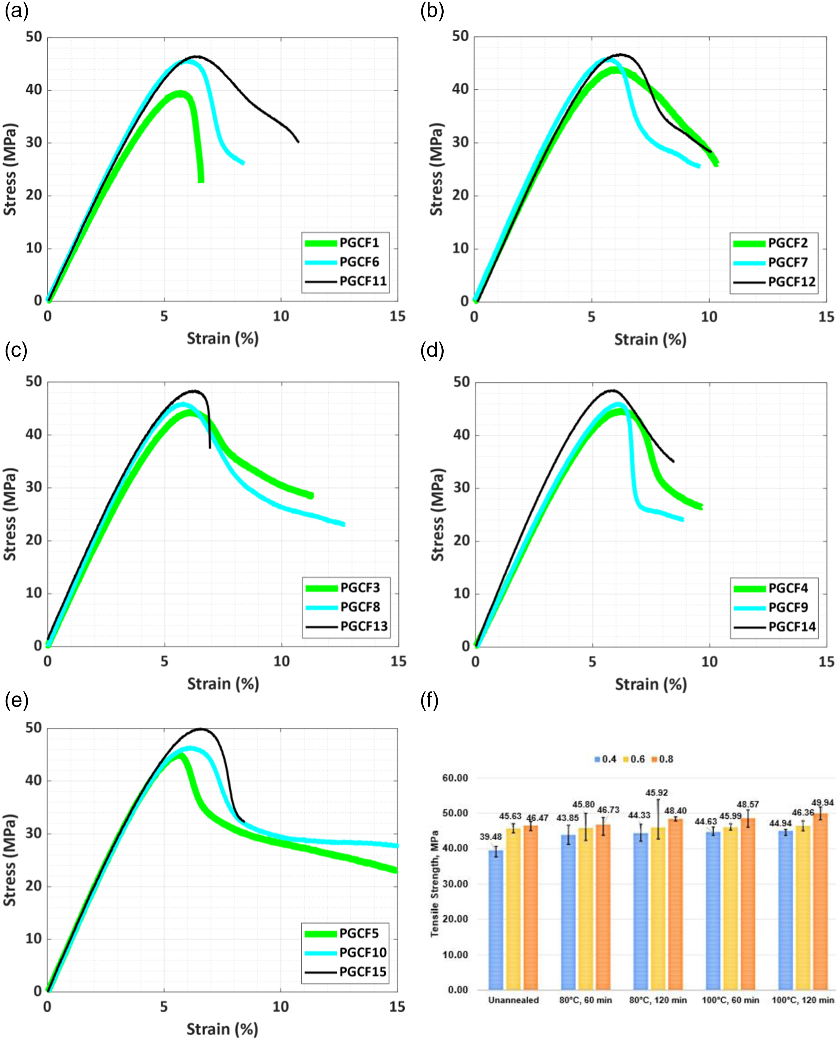
Figures 3 and 4 present stress-strain curves of the tensile test specimens for various ND values, as well as different ATP and ATM settings. In this section, the tensile behaviour of the specimens is compared while keeping the other control factors fixed. Tensile Behaviour for PETG at different ND (a) Unannealed, (b) ATP 80°C and ATM 60 min, (c) ATP 80°C and ATM 120 min, (d) ATP 100°C and ATM 60 min, (e) ATP 100°C and ATM 120 min, (f) Variation of TS. Tensile Behaviour for PETG-CF at different ND. (a) Unannealed, (b) ATP 80°C and ATM 60 min, (c) ATP 80°C and ATM 120 min, (d) ATP 100°C and ATM 60 min, (e) ATP 100°C and ATM 120 min, (f) Variation of TS.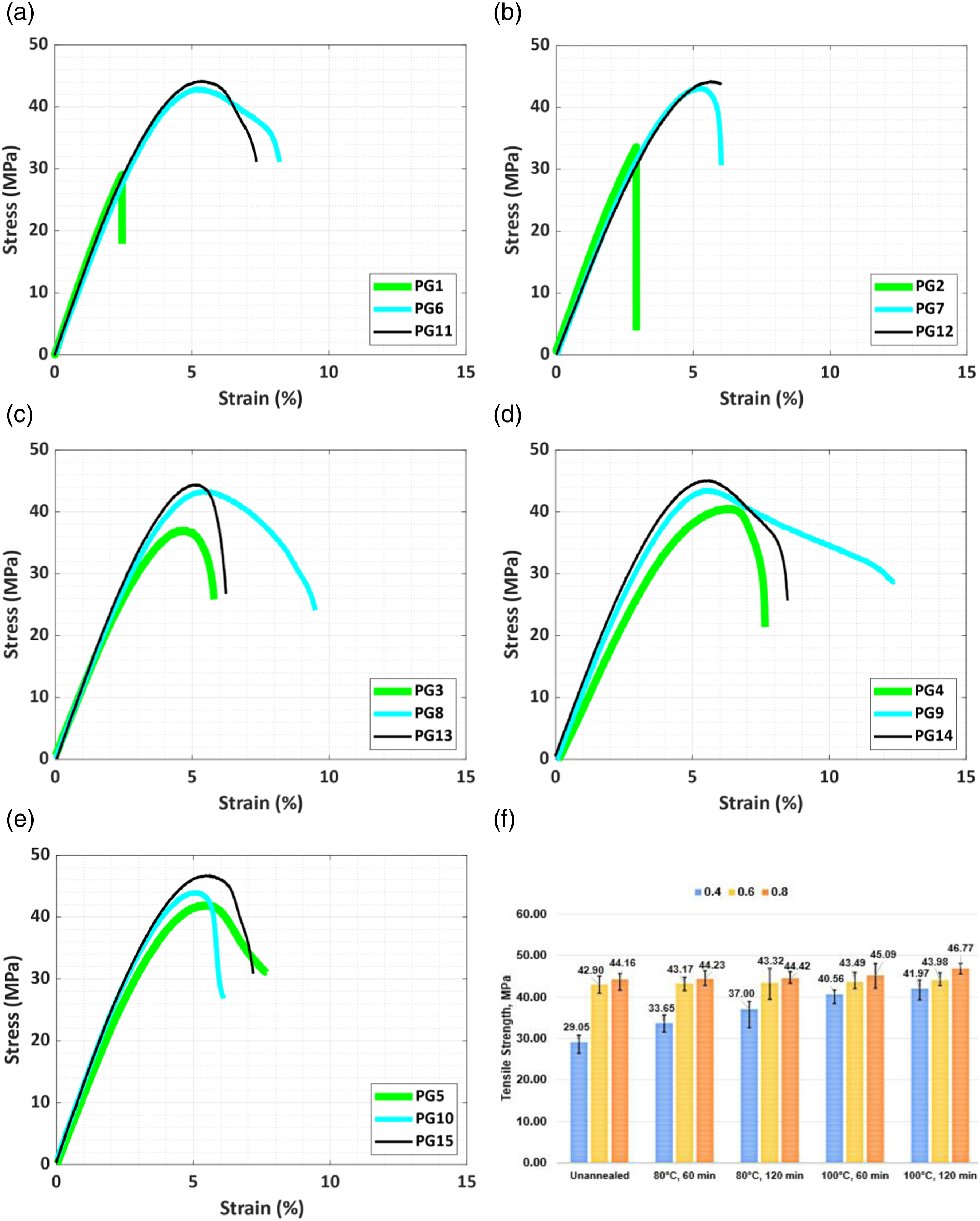
Effect of ND
The ND is a critical process variable in the FFF technique. This study investigated the influence of different ND values, specifically 0.4 mm, 0.6 mm, and 0.8 mm, on the tensile behaviour of FFF fabricated specimens made from Pure PETG and PETG-CF. The choice of ND plays a crucial role in setting the layer height during FFF printing and indirectly influences the fabrication speed by controlling the rate and amount of extruded filament material.
For Pure PETG, it was observed that raising the ND from 0.4 mm to 0.6 mm resulted in a 47.67% improvement in TS (from 29.049 MPa for PG1 to 42.898 MPa for PG6). Further increasing ND to 0.8 mm led to a 52.03% increase in TS (44.164 MPa for PG11). In the case of PETG-CF, changing ND from 0.4 mm to 0.6 mm resulted in a 15.57% increase in TS (from 39.47 MPa for PGCF1 to 45.626 MPa for PGCF6). Increasing ND to 0.8 mm further improved TS by 17.70% (46.467 MPa for PGCF11) for unannealed specimens. The tensile behaviour is enhanced by increasing the bonding area between adjacent rasters, while keeping all other parameters constant.
Annealing the PETG specimens at 100°C for 120 min and ND of 0.4 mm resulted in a TS of 41.968 MPa (PG5) with an elongation break of 12.78%. For specimens with ND of 0.6 mm (PG10) and 0.8 mm (PG15) under the same ATP and ATM conditions, TS increased by 4.79% and 11.44%, respectively. For PETG-CF, annealing at 80°C for 120 min and ND of 0.4 mm resulted in a TS of 44.332 MPa (PGCF3) with an elongation break of 23.71%. When ND was changed to 0.6 mm (PGCF8) and 0.8 mm (PGCF13) under the same ATP and ATM conditions, TS increased by 3.58% and 9.16%, respectively. The TS of the specimens is enhanced by an increase in ND, as a result of their extensive fusion and limited void distribution.
The results confirm that increasing the ND size contributes to higher product density by reducing voids formed during the FFF process. Consequently, the TS of the products increases with larger ND values. The highest TS obtained were 46.77 MPa and 49.943 MPa for Pure PETG and PETG-CF, respectively, using the ND of 0.8 mm. These values were 11.44 % and 11.13 % higher than the specimens fabricated with a 0.4 mm ND on keeping other control factors fixed. The presence of voids ultimately reducing product strength. Comparing products with different ND sizes, larger ND allow for slightly overlapping raster, leading to stronger interfacial bonding between adjacent layers. Failure surfaces typically show interfacial failures at low TS values.
Conversely, smaller ND result in in-plane neighbouring infill with minimal contact, leading to weaker horizontal bonds. These findings provide valuable insight into the effect of ND on the tensile vitality of FFF-printed materials, aiding in the optimization of control factors for improved performance and product quality.
Effect of ATM
ATM is a crucial parameter in the annealing process, which involves subjecting the specimen to a specific temperature below its melting point but above its glass transition temperature for a defined duration. This process affects the internal structure and mechanical properties of the specimen. The experimental findings demonstrate the influence of ATM on the tensile behaviour of the annealed specimens.
For Pure PETG, the TS observed was 33.648 MPa (PG2) with an ATM of 60 min and ND of 0.4 mm at an ATP of 80°C. Increasing the ATM to 120 min improved the TS by 9.97%, reaching 37.002 MPa (PG3). Similarly, for PETG-CF, the TS observed was 43.846 MPa (PGCF2) with an ATM of 60 min and ND of 0.4 mm at ATP of 80°C. Increasing the ATM to 120 min improved the TS by 1.11%, reaching 44.332 MPa (PGCF3). These results show that increasing the ATM while keeping other parameters constant significantly improves the tensile behaviour of the specimens. Longer ATM allow for more extensive crystal growth and improved ordering of polymer chains, leading to increased TS of the specimen.
Further analysis was conducted to explore the effects of ATM on TS for additional specimen configurations. For PETG, with ND of 0.6 mm, ATP of 100°C, and ATM of 60 min, the TS observed was 43.489 MPa (PG9). Increasing the ATM to 120 min improved the TS by 1.13%, reaching 43.98 MPa (PG10). Similarly, for PETG-CF with ND of 0.6 mm, ATP of 100°C, and ATM of 60 min, the TS observed was 45.99 MPa (PGCF9). Increasing the ATM to 120 min improved the TS by 0.81%, reaching 46.363 MPa (PGCF10). These findings indicate that CF addition influences the thermal conductivity and heat dissipation properties of PETG, potentially impacting the temperature distribution and heat transfer characteristics during annealing. Therefore, the heat treatment results in samples with greatly enhanced mechanical characteristics.
Tensile testing indicates that heat-treated FFF printed PETG and PETG-CF samples exhibit significantly higher TS and stiffness when compared to an unannealed control group manufactured under the same control conditions. These findings underscore the importance of ATM in enhancing the mechanical properties of FFF fabricated specimens.
Effect of ATP
The ATP is a critical factor in influencing the mechanical properties, specifically the TS, of the material. Unannealed PETG specimens with a ND of 0.8 mm exhibited a TS of 44.164 MPa. However, subjecting the PETG specimen to annealing at an ATP of 80°C for 120 minutes resulted in a slight improvement, raising the TS to 44.422 MPa (PG13), showing an increase of 0.58%. Further elevating the ATP to 100°C while maintaining other factors constant had a significant impact, with the TS reaching 46.77 MPa (PG15), a substantial improvement of 5.90%. The observed increase in TS can be attributed to the delayed crack initiation in the annealed samples due to the reduction in porosity at the filament layers, leading to improved sample strength.
In the case of PETG-CF, unannealed specimens with ND 0.8 mm had a TS of 46.467 MPa. Annealing at an ATP of 80°C for 120 minutes increased the TS to 48.395 MPa, representing an improvement of 4.20%. Increasing the ATP to 100°C resulted in a remarkable enhancement of 7.72%, reaching a TS of 49.943 MPa (PGCF15), along with a 25.71% increase in elongation at break.
These results clearly highlight that annealed samples exhibited significant improvements in stiffness and strength with increasing ATP. The maximum TS achieved for the heat-treated samples was 46.77 MPa for PETG specimen PG15 and 49.943 MPa for PETG-CF specimen PGCF15, representing an impressive 37.89% and 20.95% increase, respectively, compared to the minimum TS of unannealed specimens PG1 (29.049 MPa) and PGCF1 (39.479 MPa).
In addition, the results demonstrate a significant relationship between the ATP and tensile properties, with higher ATP resulting in more substantial improvements in TS. Annealing is a complex process that requires careful consideration of the balance between time and temperature to achieve optimized results. It is essential to have a strong rationale for annealing these materials, considering that the improvements in mechanical properties may be limited for samples treated at low heat-treatment temperatures compared to those treated at higher temperatures.
Microstructural Investigation
The aim of this study was to investigate the effect of heat-treatment on the failure response of FFF fabricated specimens. To do this, the researchers used a SEM to analyse the fractured surfaces of the tensile test specimens. The main goal of the SEM analysis was to understand the deformation and bonding quality of the samples.
In FFF fabrication, the bonding between the layers is not easily visible, so the researchers took high-magnification SEM micrographs to get a clear visualization of the bonding quality. Figure 5 shows the SEM images of the tested PETG tensile specimens. Among the tested samples, three were chosen for further analysis based on their outstanding tensile behaviour in both the unannealed and annealed states. Specifically, specimen PG11 exhibited the highest ultimate TS among the unannealed PETG specimens, while samples PG14 and PG15 showed the best TS among the annealed PETG specimens. Facture morphology for the PETG specimens at same ND of 0.6 mm, unannealed and annealed specimen (a) Specimen PG11, (b) Specimen PG14, (c) Specimen PG15.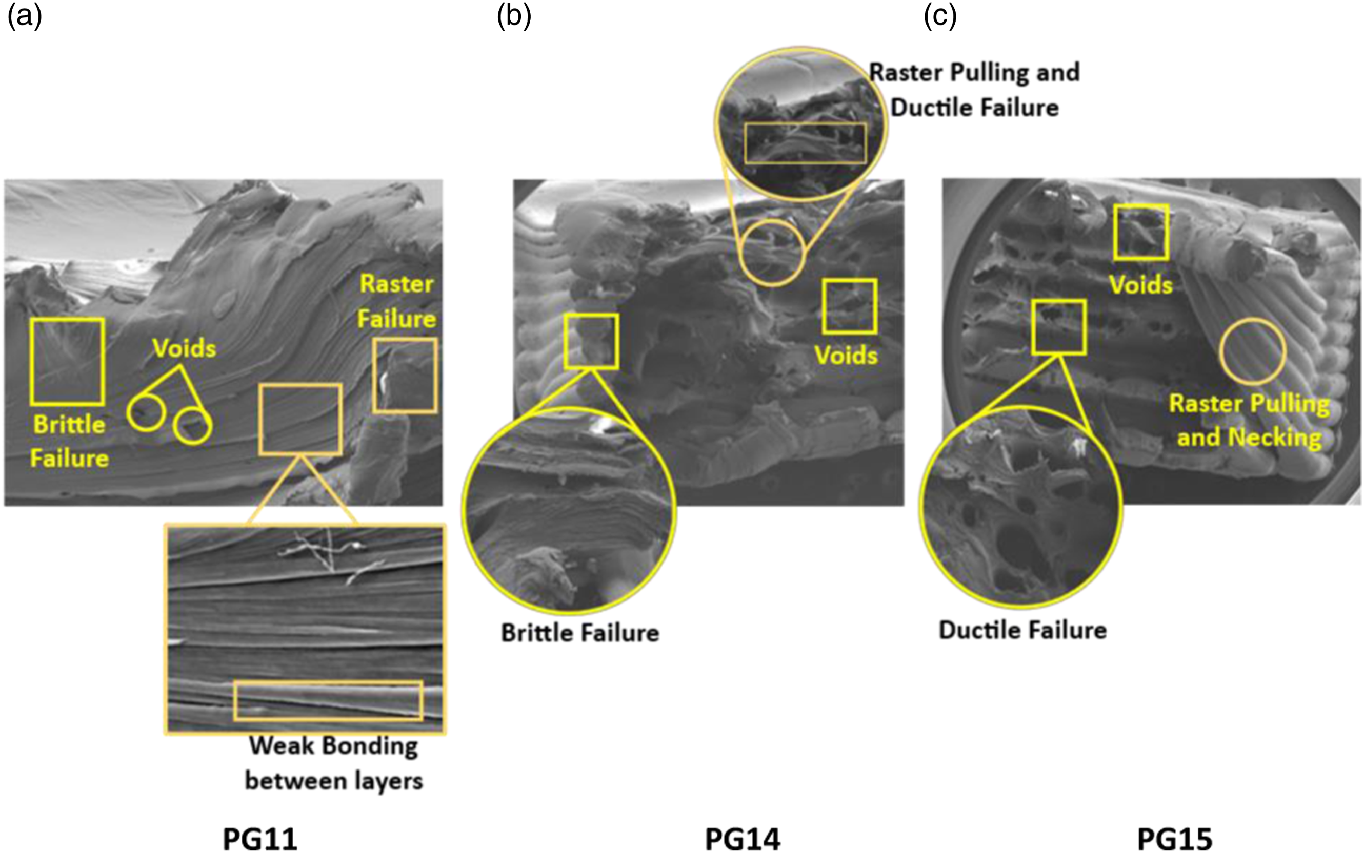
The SEM analysis provided valuable insights into how heat-treatment affected the deformation and bonding characteristics of these high-performing samples. In the subsequent fracture analysis, the researchers discussed the termination of interfaces and the observation of voids.
In materials, the interface between different components plays a crucial role in stress propagation. When subjected to tensile stress, weak regions like pores or discontinuities can cause material fracture. In the case of PETG, the interface between the raster was found to be the first to fail, with numerous micro-voids forming at the interface. This led to the initiation and propagation of cracks throughout the material, as seen in Figure 5(a), which showed the lowest TS of 44.164 MPa among the specimens fabricated utilising ND of 0.8 mm. As the crack propagated, the bonding between adjacent raster initially became stronger, but eventually, they started to separate, leading to a sequence of events until the final fracture occurred.
During the analysis of annealed PETG specimens, significant differences in their failure behaviour were observed. Sample PG14, which underwent heat treatment at 100°C for an ATM of 60 minutes, exhibited characteristics of raster pulling brittle fracture with a flat fracture surface, as depicted in Figure 5(b). Notably, the number of inter voids decreased, and the failure mode transitioned from purely brittle to a combination of brittle and ductile behaviour, resulting in an increase in the specimen’s TS.
In contrast, sample PG15, (Figure 5(c)) subjected to heat treatment at 100°C for an ATM of 120 minutes, displayed characteristics of ductile fracture, showing only raster pulling and necking. This sample exhibited the highest TS of 46.77 MPa among all tested specimens. Additionally, the heat-treatment process led to a significant reduction in voids within the material, contributing to the superior TS observed.
To gain further insights into the failure mechanism, the microstructure of PETG-CF was examined under both unannealed and annealed conditions as shown in Figure 6. During the initial deflection stages, voids and small cracks were observed on the tension plane, particularly in the CF composite, where the transverse broken line appeared irregular instead of straight. Facture morphology for the PETG-CF specimens at same ND of 0.6 mm, unannealed and annealed specimen (a) Specimen PGCF11, (b) Specimen PGCF14, (c) Specimen PGCF15.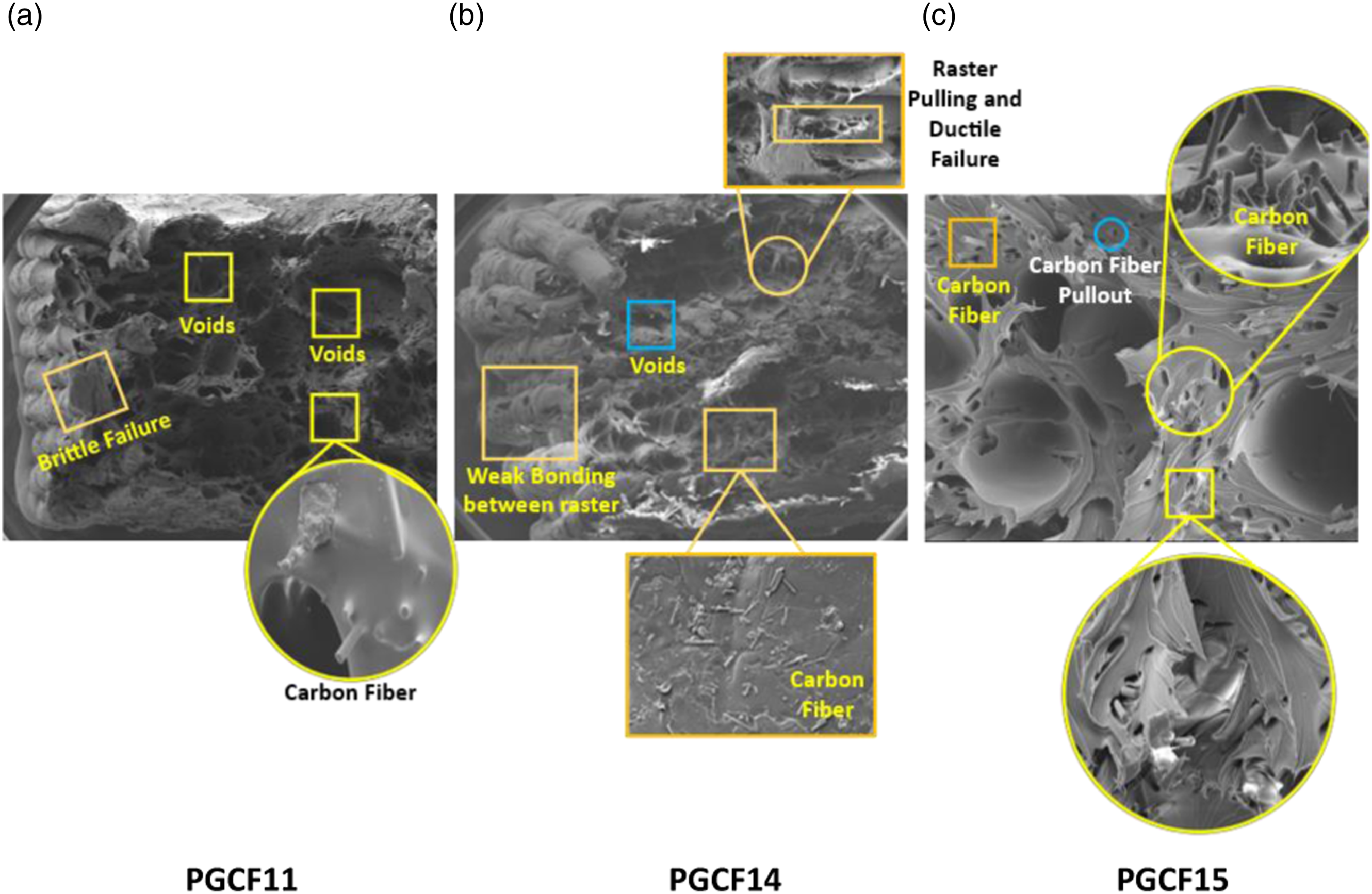
When applying a tensile load to a composite material, stress concentration at the interfaces can lead to crack formation and fibre fracture. This emphasizes the importance of interface integrity in determining the overall mechanical performance of the composite. Weak raster-to-raster bonding, CF breakage, and CF withdrawal were identified as the causes of the specimen’s brittle deformation, resulting in the lowest TS of 46.467 MPa observed in the PGCF11 specimen, as shown in Figure 6(a).
However, when the PGCF14 specimen of PETG-CF underwent the heat treatment process at 100°C for 60 minutes, it exhibited characteristics of raster pulling and ductile fracture, as shown in Figure 6(b). The observed phenomenon can be linked to the relaxation of residual stress in the FFF-printed sample during the annealing process. This led to an enhancement in the crystallinity of PETG-CF. Despite this improvement, the molecular chains of PETG-CF remained in a relaxed state with significant elongation, which played a crucial role in releasing stress and promoting better bonding between the fibres and PETG matrix. As a consequence, the initiation and propagation of cracks were delayed, and the material exhibited increased resistance to interlaminar shear stress.
After the heat treatment process, some small voids were still visible on the cross-section of PETG-CF. However, an interesting observation was made that these voids decreased significantly only when the ATM reached 120 minutes. As the thermal treatment temperature and duration increased, the specimen’s porosity decreased even further. As a result of this reduction in voids and porosity, the specimen exhibited a complete ductile failure mode, with both the raster and CF pulling occurring during the tensile test. This behaviour is illustrated in Figure 6(c). Remarkably, this improvement in the microstructure and bonding characteristics of the specimen due to annealing resulted in a maximum TS of 49.943 MPa. This demonstrates the positive effect of annealing on enhancing the mechanical characteristics of PETG-CF, leading to a significant increase in TS.
Additionally, the SEM images proved to be valuable for identifying voids or porosities inside the specimen. These voids could potentially lead to a decrease in density and TS, making them useful for validating the mechanical tests performed.
Statistical Investigation
Statistical analysis is carried out utilizing ANOVA with TM and RSM to assess and compare the impact of control factors to the outcome target.
Analysis of variance with TM
The aim of this study was to investigate the impact of specific control factors on the TS of PETG and PETG-CF specimens. To achieve this, a systematic experimental design called Taguchi’s L12 array Design of Experiments (DOE) and statistical analysis through ANOVA were employed.
The control factors considered in the study were ATP with two levels (80°C and 100°C), ATM with two levels (60 min and 120 min), and ND with three levels (0.40 mm, 0.60 mm, and 0.80 mm). These variables were meticulously chosen because they have a substantial impact on the mechanical characteristics of FFF-fabricated parts. To evaluate the performance of each control factor, signal-to-noise ratios (SNRAs) were calculated and analysed using statistical software called MINITAB 21. Higher SNRAs indicate better performance of the control factors in enhancing the TS of the specimens.
The results, depicted in Figure 7 with SNRA plots and interaction plots, provide valuable insights into how the different control factors (ND, ATP, and ATM) affect the TS of both PETG and PETG-CF specimens. Moreover, ANOVA was used to determine the contribution of each control factor to the variability of the TS. The coefficient of determination (R2) was calculated, indicating the proportion of the total variation in TS explained by the model’s factors. For PETG and PETG-CF specimens, R2 values of 83.91% and 95.17% were obtained, respectively. Main effects and interaction plots showing the impact of the control factors on TS for (a) PETG, (b) PETG-CF generated using the SNRA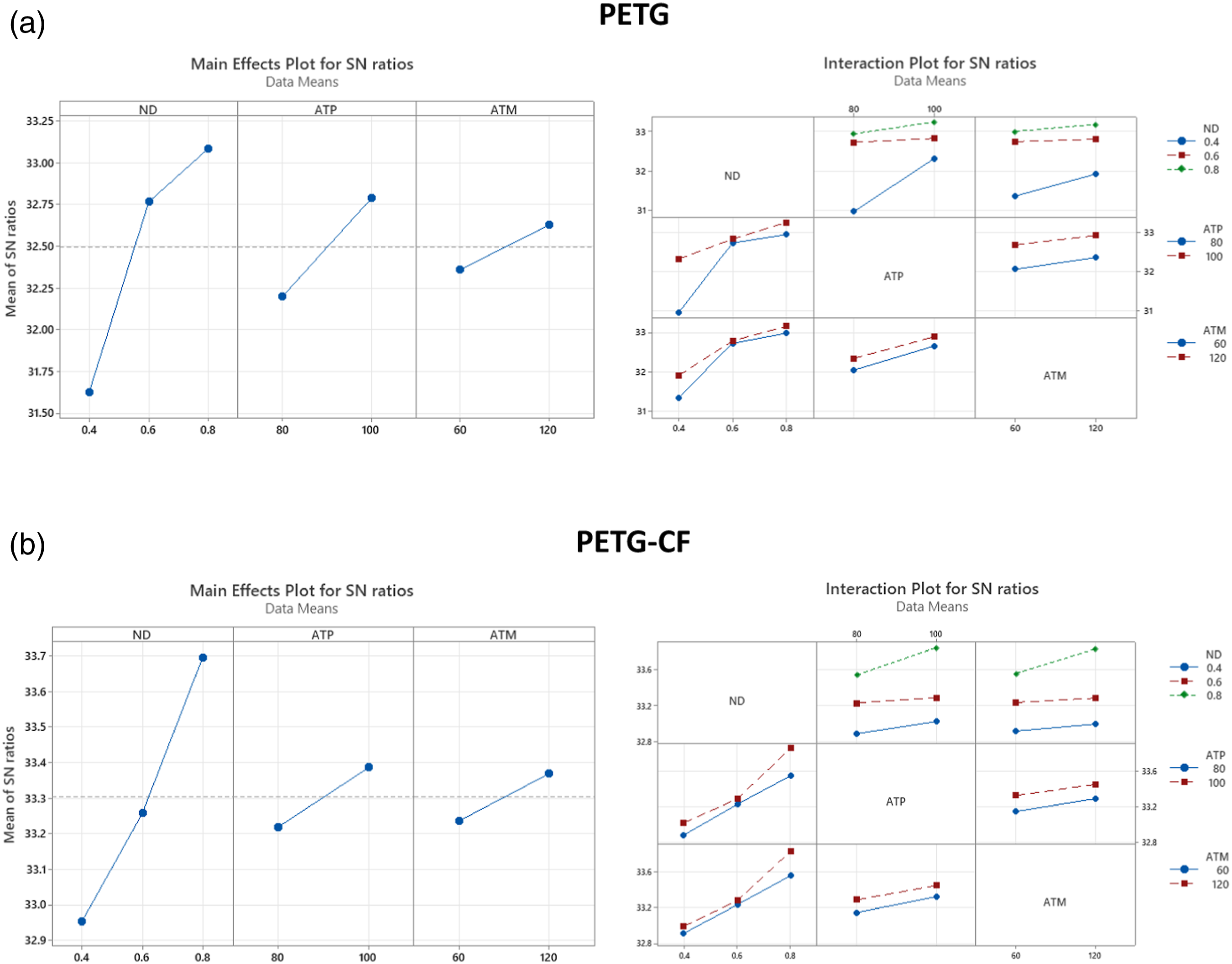
ANOVA using Taguchi for TS of A) PETG, B) PETG-CF.
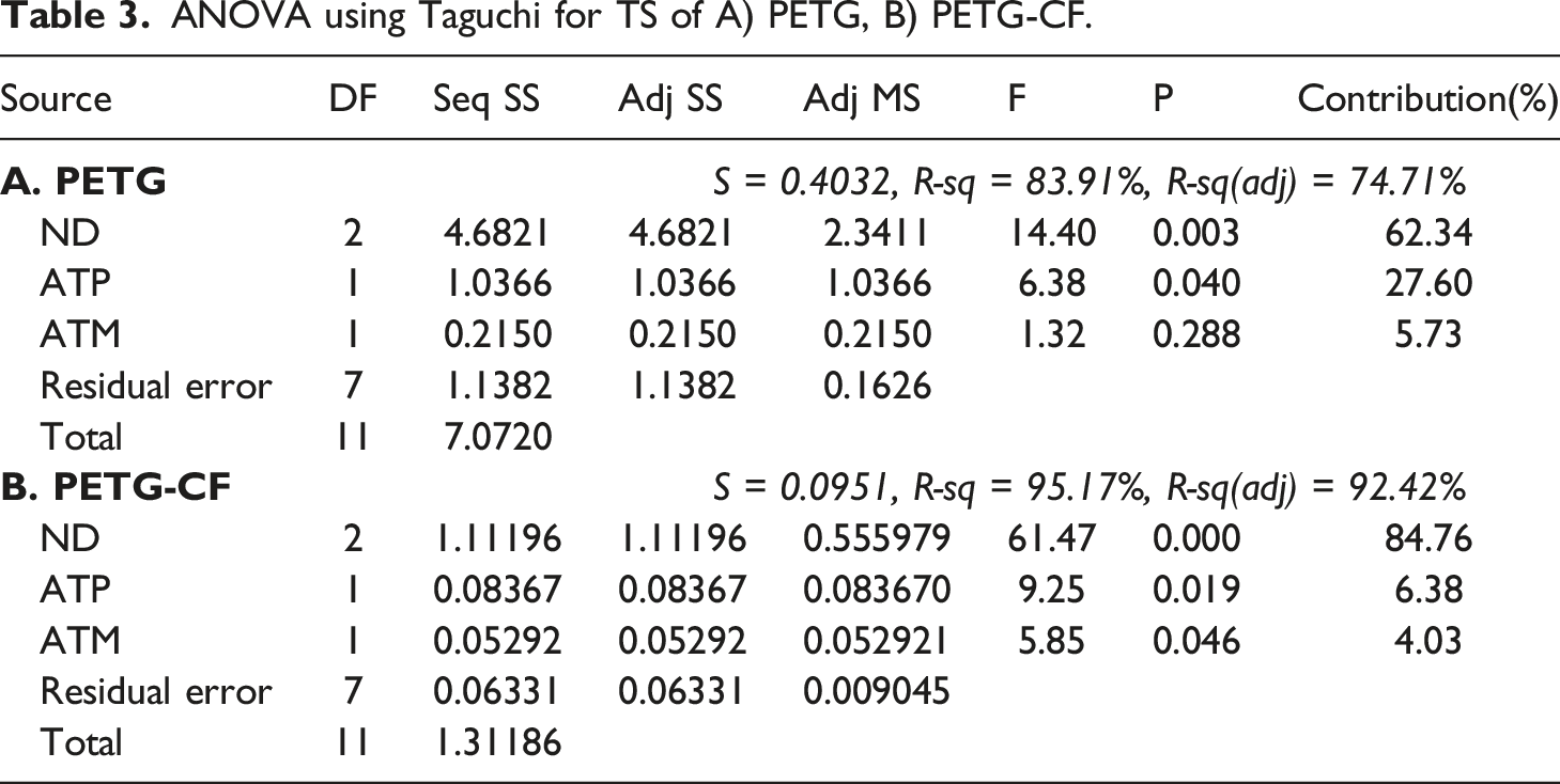
This ANOVA analysis has allowed for the identification of the key factors that significantly affect the TS of the specimens. Understanding these influences is crucial in selecting the most favourable control factors for optimization, enabling the production of FFF fabricated parts with improved mechanical properties. By focusing on optimizing the ND and ATP, manufacturers and researchers can achieve enhanced TS and overall performance of the FFF-printed materials.
Analysis of variance with RSM
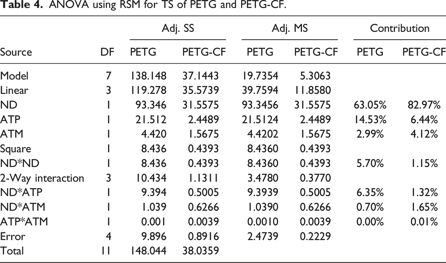
The present investigation employed an ANOVA to determine the relative significance of various control factors and their impact on the overall outcome. The percentage change in each input control factor that resulted in the observed variation in the response was calculated using normalized sum of squares for Linear effects (ND, ATP, and ATM), Square effects (ND*ND), and 2-way interaction effects (NHD*ATP, ND*ATM, and ATP*ATM). To ascertain the importance of the influence of ATP, ATM, and ND, a 95% confidence interval was utilized, corresponding to a statistical alpha value of 0.05. The primary objective of this analysis was to identify the optimal combination of control factors that maximizes TS.
ANOVA using RSM for TS of PETG and PETG-CF.
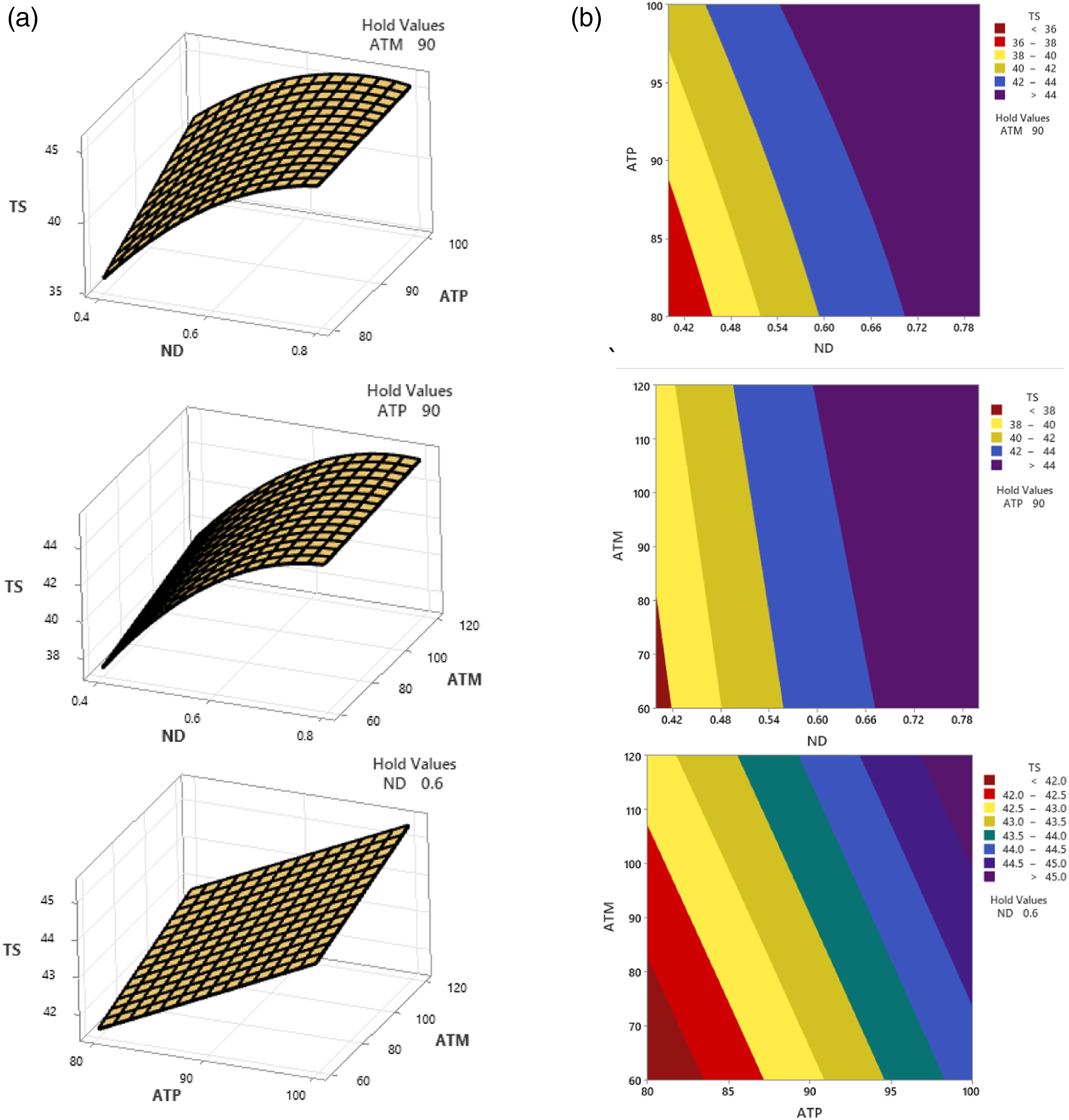
(a) Contour plot and (b). Surface plot for tensile behaviour of PETG
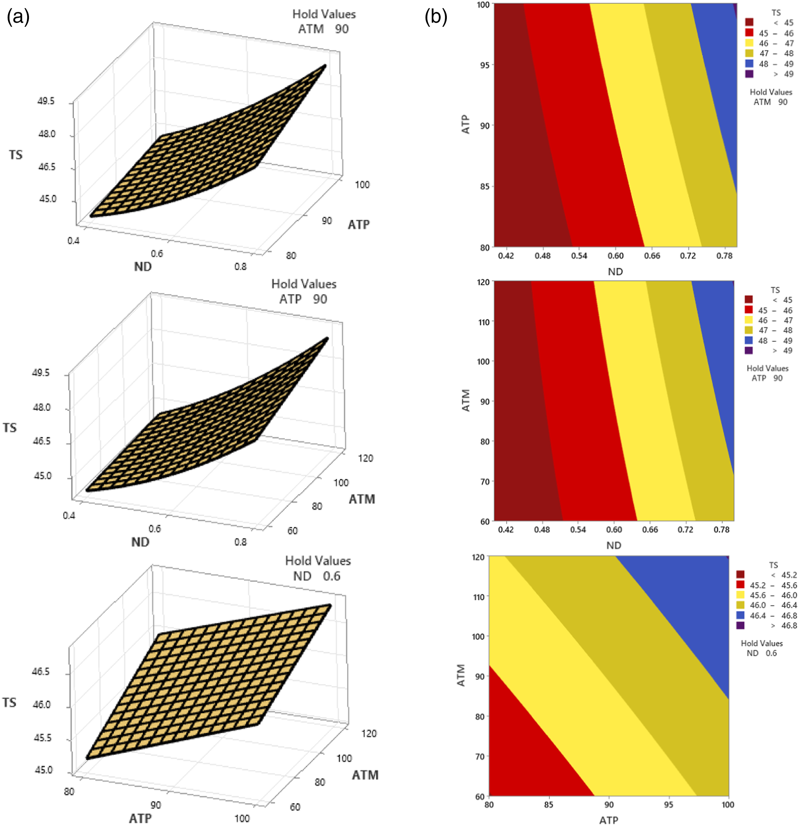
(a) Contour plot and (b) Surface plot for tensile behaviour of PETG-CF.
The application of statistical tools such as the TM and RSM in the analysis of TS for different fabricated elements, while manipulating selected control factors, unequivocally establishes the paramount role of ND in influencing the TS of both PETG and PETG-CF specimens. Additionally, this analysis elucidates the considerable influence of ATP and ATM in substantially impacting the TS of the fabricated polymer composites. The findings from this rigorous study shed light on the key factors driving the mechanical performance of the specimens, paving the way for optimization and advancement in the field of additive manufacturing.
Conclusions
The primary objective of this study was to investigate the tensile properties of PETG and PETG-CF specimens produced using FFF, focusing on the effects of three key control factors: ND, ATP, and ATM. The experimental results clearly demonstrated that changes in ND and ATP had a significant impact on the TS of both PETG and PETG-CF composites. The statistical analysis, utilizing the TM and RSM, revealed that these control factors played a crucial role in determining TS, with significance levels exceeding 95% for both materials.
Notably, ND emerged as the most influential factor affecting the TS of PETG and PETG-CF specimens. The highest TS of 46.77 MPa and 49.943 MPa were achieved for PETG and PETG-CF, respectively, when using a ND of 0.8 mm, annealed at an ATP of 100°C for an ATM of 120 minutes. These values represented a remarkable improvement of 61% and 26.51% compared to unannealed specimens fabricated with a 0.4 mm ND. Furthermore, increasing the ND from 0.4 mm to 0.8 mm resulted in the most significant enhancements in TS, with improvements of 52.03% for PETG and 17.70% for PETG-CF. Moreover, the ATM exhibited a greater influence on the TS of PETG-CF materials than on PETG materials. Extending the ATM from 60 to 120 minutes led to improved TS in PETG-CF specimens.
SEM analysis revealed that heat-treatment positively impacted PETG samples. Untreated samples had weak interfaces and exhibited brittle fractures with micro-voids. In contrast, heat-treated samples showed fewer voids, and their failure mode transitioned from purely brittle to a combination of brittle and ductile behaviour. As a result, the heat-treated samples exhibited increased TS, making them more robust and less susceptible to failure under stress.
The study emphasized the importance of proper thermal annealing conditions, as they can substantially enhance the mechanical properties of thermoplastic polymers. Annealing facilitated the orderly arrangement of polymer chains, increasing the crystallinity and consequently strengthening the materials.
The findings of this research hold great promise for a wide range of applications in automotive and aeronautical components that demand models with a high strength-to-weight ratio. Using the process of thermal annealing as a major approach which can enable the production of strong PETG-CF specimens with superior mechanical properties.
Footnotes
Acknowledgements
To conduct the tensile tests, the researchers gratefully thank the assistance of ACMS, IIT Kanpur, India. Evaluation of the fractography is greatly aided by the assistance of the SEM lab, Department of Chemistry, DEI. Additionally, we appreciate the AICTE grant (file number. 8-88/FDC/RPS (POLICY-1)/2019-20) that was given to us.
Declaration of conflicting interests
The author(s) declared no potential conflicts of interest with respect to the research, authorship, and/or publication of this article.
Funding
The author(s) received no financial support for the research, authorship, and/or publication of this article.