
Abstract
In the present study, the flexural, morphological, and shape memory properties of polylactic acid (PLA) matrix sandwiched with polyvinylidene difluoride (PVDF) Nanofibers (NFs) interleave composite structures have been investigated for applications of 4D printing such as smart grippers, and smart actuators. Firstly, an electrospinning process was carried out to form a PVDF NFs mat (thickness: 0.10–0.20 mm) under a flow rate of 3 µL/sec, an applied voltage of 12 kV, and a TCD of 100 mm. Further, the PVDF NFs mat was deposited in between the PLA layers, primed through fused filament fabrication (FFF) based 3D printing to manufacture the PLA-PVDF NFs-PLA based structures. In the next stage, the flexural properties were investigated for manufactured composite structures. The results highlight that the flexural strength of the composites was enhanced by 6.47% as compared to PLA. Results of the study are supported by a scanning electron microscope (SEM), X-ray diffraction (XRD), Fourier transform infrared (FTIR), V-I, V-R, and shape memory analysis. The finding of the study suggests that composite structures primed by higher mat thickness and zig-zag infill pattern have resulted in higher electrical resistance and better shape memory effect. However, increasing the voltage in the composite structure having higher mat thickness with a zig-zag fill pattern has resulted in a higher resistance drop.
Introduction
Additive manufacturing (AM) technology has been used for converting a 3D model into a real part by the addition of materials in layer-by-layer form. The ability to print large structures, eliminate printing errors, and enhance mechanical properties is one of the primary needs for the development of additive manufacturing technology.1,2 Some materials show shape-changing characteristics concerning time when exposed to any environmental stimuli and this process of changing the shape of 3D manufactured parts is known as 4D printing.3,4 These smart materials can be fabricated by using the FFF technique which is low operational cost and possesses great potential in the smart components and smart structures applications.5,6 The electrospinning technique is commonly used for the production of non-woven nanofibrous mats and is used for numerous biomedical applications.7,8 The optimized process parameters such as flow rate, applied voltage, and TCD are responsible for better electrospun NFs and settings of process parameters affect the diameters of NFs.9,10 Poly (L-lactic acid) (PLLA) NFs were produced utilizing the electrospinning technique by combining polymer and chloroform in an 8:100 ratio. PLLA NFs have tensile and flexion strengths of 40.68 ± 2.99 MPa and 91 ± 3.55 MPa respectively, which nearly resemble the natural anterior cruciate ligament (ACL). 11 Previous studies have reported the composite formation by use of NFs.12,13 To manufacture the hydroxyapatite NFs grafted PLA (HANF-g-PLA) composite, the PLA chain has been added onto the HANF, which was advantageous for enhancing the interaction between the PLA matrix and HANF. HANF-g-PLA has resulted flexural strength of 124 MPa, which was 25% improved than PLA resin. 14 Due to the thorn-like structure, the mechanism of interlocking of the molecules between the NFs surface and the matrix material increased which directly enhanced the interfacial adhesion and mechanical properties of the composite structure. 15 Thermoplastic materials are generally brittle and experienced cracking as compared to thermoset polymers. So, the electrospinning process has been used for the preparation of electrospun nano-cellulose from cellulose acetate (ECA) and reinforced in the epoxy matrix as a filler and resulting in 20% enhancement of flexural strength and 17% of flexural modulus. 16 Electrospun NFs have been woven into an eight-ply woven carbon fiber fabric at each interlayer to manufacture a modified carbon fiber reinforced polymer (CFRP) laminate. The electrospun polyacrylonitrile (PAN) NFs raised the strength to load-bearing by 18.9%, flexural strength by 55.91%, and flexural modulus by 20.9% in the load-bearing tests of the pin-joined laminates. 17 A manufactured multiscale hybrid carbon fiber composite with reinforcement epoxy at interfaces with core-shell NFs possessed the property of self-healing. 18 Using co-electrospinning, the ultrathin self-healing fibers were produced. 19 It has been reported the development of a hybrid multi-scale epoxy composite made of electrospun carbon NFs (ECN) mats in the interlaminar spaces between typical carbon fiber fabrics. 20 To fabricate the carbon fiber fabric hybrid polymer composites, the semi-aligned layers of carbon NFs have been added in various weight percentages (0–2.0 wt%) at the interlaminar region between carbon fiber fabric plies. The results show an improvement of 175% and 200% with 1.1 wt% of the semi-aligned carbon NFs layers for the bending strength and bending modulus respectively. 21 Using electrospinning, varying weights of multi-walled carbon nanotubes (MWCNT) with or without polyvinyl alcohol (PVA) NFs mats were utilized to reinforce epoxy composite laminates made of carbon fiber reinforced by electrospinning (CFRE). PVA NFs mats that have been varied with 1, 3, or 5 wt % MWCNT. The CFRE composites possessed flexural strength of 267 MPa, but the flexural strength was enhanced by 31% of CFRE composites reinforced with 1 wt% of MWCNT/PVA NFs mat was observed 350 MPa. 22 Flexible carboxylated carbon nanotubes (CNTs)/polyamide 66 (PA66) nanofibrous mat interleaved in the fabricated carbon fiber/epoxy Laminates, and the carboxylated CNTs reinforcing effect increased the flexural strength and flexural modulus of laminates. 23
The previous studies have reported the PLA-cellulose nanowhiskers (CNWs) composite NFs formation. 24 Electrospinning has been used to fabricate PLA-nanodiamond composite NFs with a nanodiamond loading of less than 1%. The maximum tensile strength, Young's modulus, elongation at break, and fracture toughness of composite NFs of PLA reinforced with 1 wt% nanodiamond. 25 To prepare PLA- tea phenol (TP) nanocomposite NFs, ratios of 5:1, 4:1, 3:1, and 2:1 of tea polyphenol (TP) to PLA were utilized. The inclusion of TP has affected the hydrophilic and hydrophobic characteristics. Escherichia coli and Staphylococcus aureus have more resistant to antimicrobial effects of PLA-TP (3:1) are 92.26 ± 5.93% and 94.58 ± 6.53%, respectively. Potential applications for PLA-TP (3:1) in food packaging. 26 The optimal conditions to produce the needed and most homogenous diameter of chitosan (CS)/polyethylene oxide (PEO) NFs are 2:1 (w/w) blend ratio, 25 kV applied voltage, 200 mm TCD, and 45° spinning angle. 27 Treated basalt fibers (TBFs) are included in nylon (NY)/epoxy (EP) (5:1) at different weight ratios of 5, 10, 15, 20, and 25 wt%. The improvement of 76% and 87% occurred in tensile strength and Young’s modulus respectively, at 15 wt % TBF. 28 Exfoliated graphite nanosheets (EGNS) were mixed with polystyrene (20 wt%) in various weight ratios of 3, 6, and 9 wt% to manufacture composite NFs mats. The composites' tensile strengths and Young's modulus are enhanced compared to PS NFs with increasing EGNS concentrations. 29 In a weight ratio of 1, 2, 3, 4, and 5, NY was mixed with epoxy to produce hybrid NFs made of NY and epoxy (EP) polymers. The sequencing technique used to dissolve both polymers and the minimum diameter and standard deviation for hybrid NFs were determined to be 180 ± 35 nm.30,31 These electrospun NFs can be used with polymer composites for various applications such as tissue engineering, 32 drug delivery, 33 filtration, 34 textiles, 35 and smart actuators.36,37
This literature is evident that various studies were reported related to the fabrication of NFs from a variety of polymers. But hitherto, very few studies were reported related to the reinforcement of NFs in the 3D printed polymer composite. Very less studies have been reported on the flexural and shape memory properties of PLA-PVDF NFs-PLA interleave composite structures primed through additive manufacturing. This research work is the extension of the previous study reported by Thakur et al. (2023) of PLA-PVDF NFs-based sandwich composite structures for self-folding structures. 38 In the previous work, the study was limited to investigations of the tensile and thermal properties of the PLA-PVDF NFs-based composite structures, and other supporting properties on two samples that exhibited the best and worst tensile strength. The extension has been made in the present study by exploring the flexural properties of the PLA-PVDF NFs-PLA interleaves composite structures. In addition, the supporting investigations of the shape memory effect, VI and VR characteristics, and fractural properties have been performed on the two fracture samples that exhibited the best and worst flexural strength. This present work outlines the potential of the present study in smart gripper applications.
Material and methods
PLA-PVDF NFs-PLA interleaves composite structures were manufactured by using filament of PLA (Dia of filament: 1.75 ± 0.05 mm) and PVDF NFs. The PVDF NFs were prepared by using the electrospinning process (Make: E-Spin NanoTech). Figure 1 shows the methodology for the fabrication of PLA-PVDF NFs-PLA based interleave composite structure. N, N dimethylformamide (DMF), and acetone were the chemicals used for the dissolution of PVDF pellets to form a polymeric solution. The DMF and acetone were used in the ratio of 60:40 v/v% and 14 wt% concentration of PVDF pallets. The composite parts were 3D-printed by using the FFF technique of AM. Methodology for fabrication of PLA-PVDF NFs-PLA interleave composite structure.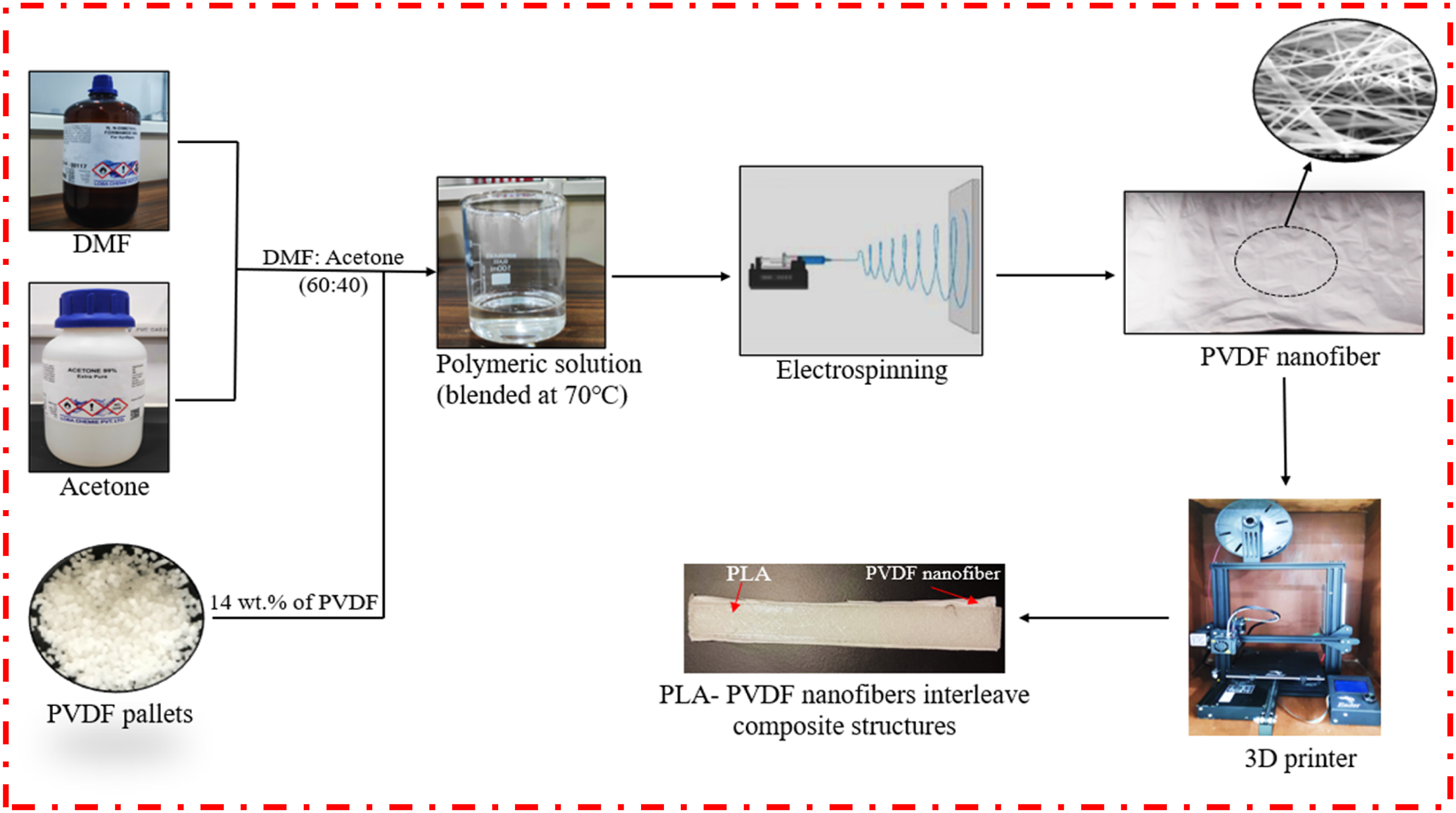
Experimentation
Preparation of PLA-PVDF NFs-PLA-based composite structures
To make the polymeric solution, PVDF pallets were combined with acetone and DMF. The solution turned viscous when the PVDF pellets were completely dissolved. The syringe with a 10 mL capacity was filled with this viscous solution and fastened to the spinneret. The flow rate, applied voltage, and TCD were considered as the process parameters for the preparation of NFs. The optimized settings for electrospun NFs were a flow rate of 3 µL/sec, 100 mm TCD, and 12 kV voltage applied. 38 The syringe tip received a high voltage and the collector rpm was set at 1000 r/min. From the previous literature, it has been observed that the increment in speed or rpm of the collector is responsible for the directionally ordered fibers with fine diameters. 39 At a certain flow rate, the solution begins to extend toward the collector as a result of the electromagnetic attraction between the collector, and the tip of the syringe. The chemical evaporates along the pathway from the collector to the syringe tip. And the polymers collected by the collector in the NFs form. The average diameter of the PVDF NFs was observed 176 nm (from SEM analysis), based on the pilot experimentation.
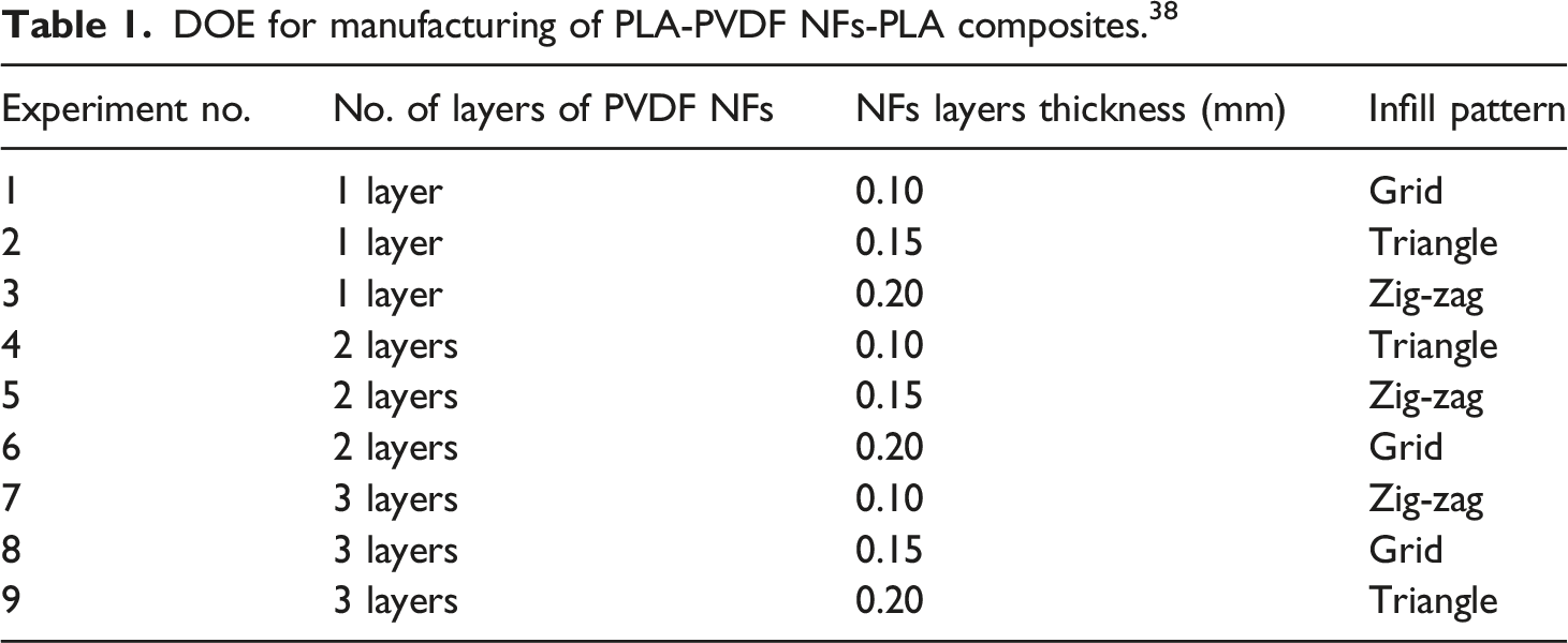
DOE for manufacturing of PLA-PVDF NFs-PLA composites. 38
Effect of process parameters of 3D printing and electrospinning.
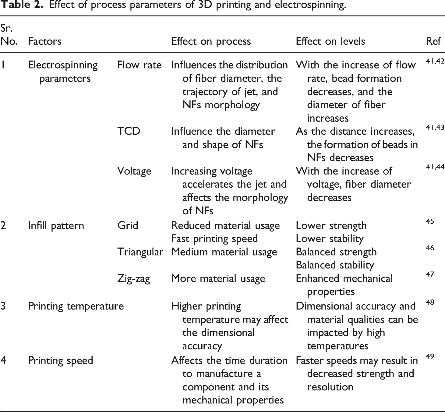
Figure 2 shows the illustrative diagram of PLA- PVDF NFs-PLA interleave composite structures. The sandwiching of the PVDF NFs mat was done in between the PLA additive layers after regular intervals. Illustrative diagram of PLA-PVDF NFs-PLA-based composite structures.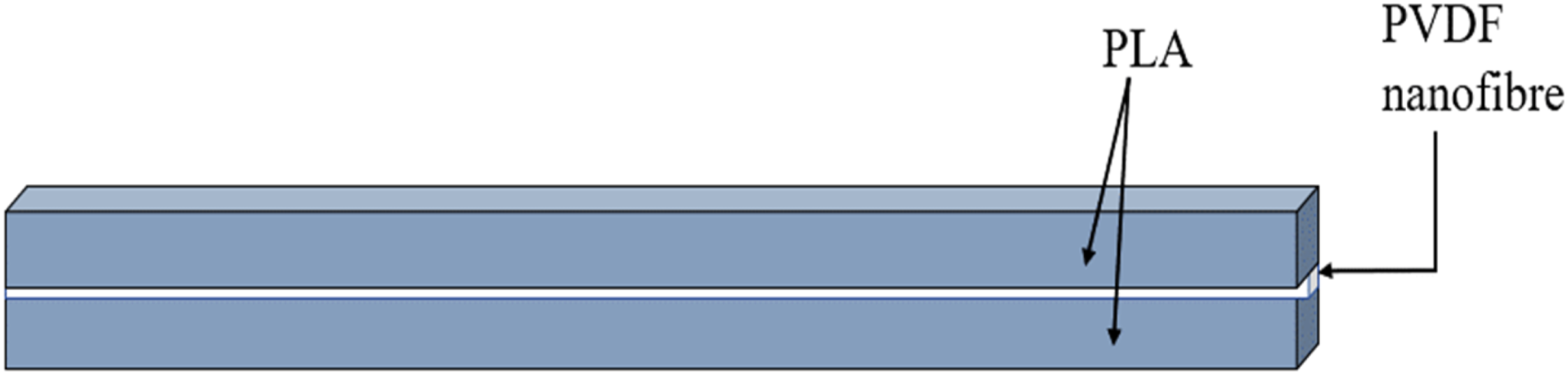
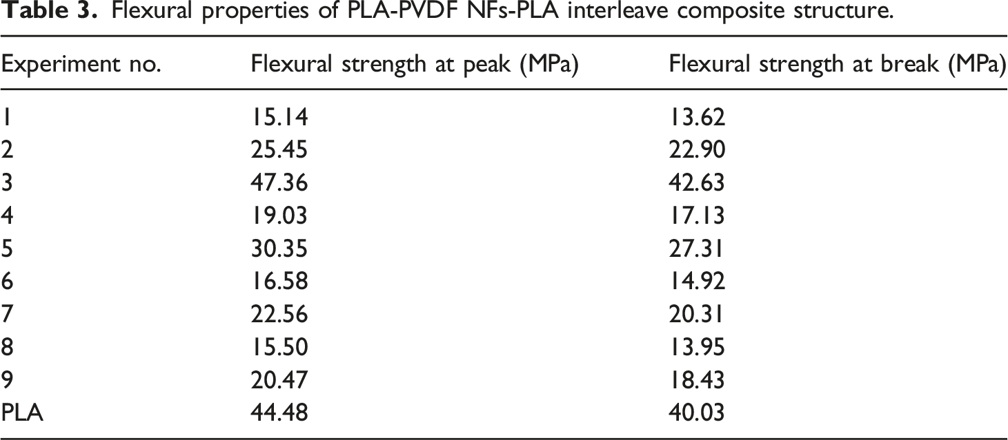
Flexural testing
The universal testing machine (UTM) (Make: Shanta Engineering) was used to investigate the flexural properties of the PLA-PVDF NFs-PLA interleave composite structures. Figure 3(a) shows the illustrative diagram of the flexural testing setup. The strain rate of 20 mm/min was used in flexural testing. After the completion of flexural testing, the fractographical properties were investigated by performing SEM analysis. Figure 3(b) shows the fractured samples of PLA-PVDF NFs-PLA composites structures after flexural testing (a) Illustrative diagram of the flexural testing procedure and (b) Fractured samples of PLA-PVDF NFs-PLA composites structures after flexural testing.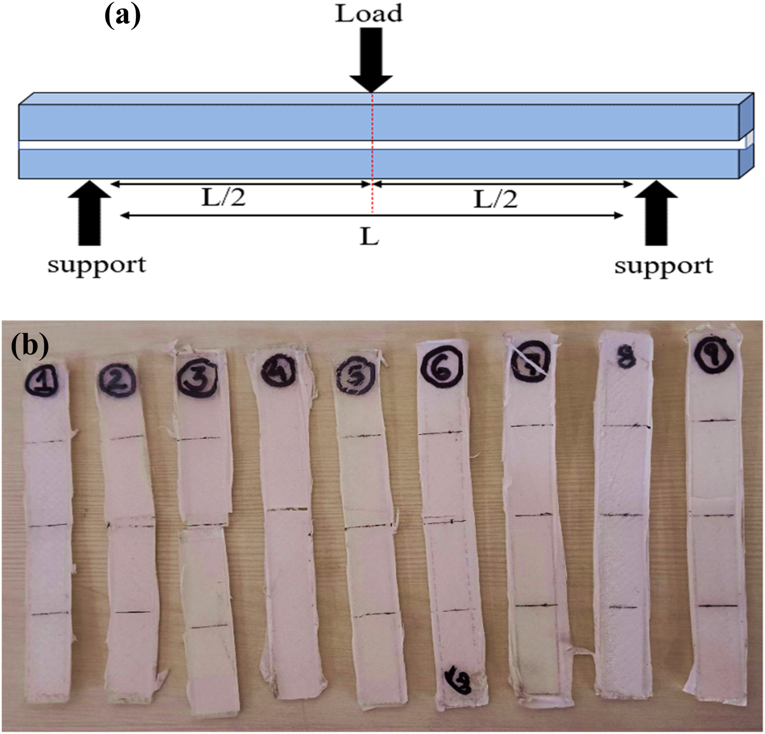
SEM analysis
SEM (Make: Jeol, Model: JSM IT500) was used for analyzing the fractographical properties of PLA-PVDF NFs-PLA interleave composite structure. A 15 kV power source was used in the mode of high vacuum during the fracture analysis. The study of the microscopic fractures was done on the magnification of ×50 and ×80.
EDS analysis
EDS analysis was carried out to ascertain the elemental composition of the PLA-PVDF NFs-PLA interleaves composite structures. By connecting an EDS detector to an electron microscope, compositional data was collected.
Roughness and porosity profiles
The SEM images were used to evaluate the profiles of roughness and porosity of the PLA-PVDF NFs-PLA interleave composite structure. The mechanical properties can be analyzed from the profiles of roughness and porosity of manufactured composite structures.
XRD analysis
Cu-K radiation with a wavelength of 1.54060 was used to evaluate the sample’s crystal structure. The diffraction patterns were recorded at a scanning rate of 5°/min with an angle of 2Ө between 5 and 90.073°.
FTIR analysis
The setup of FTIR (Make: Analytical Technologies, India) was utilized to investigate the chemical analysis of PLA-PVDF NFs-PLA interleave composite structure. The chemical interactions and presence of functional groups in the composite matrix were identified by performing FTIR analysis. FTIR analysis was performed in the range of 3000–4000 cm−1.
V-I and V-R characteristics
The electrical properties of samples were ascertained by using a Source meter electrical test apparatus (Make: Keithley 2400, USA). The charge flow and the resistance of the composite structure were observed using characteristics of V-I and V-R.
Shape memory analysis
The manufactured PLA-PVDF NFs-PLA interleave composite structures were exposed to a thermal stimulus of 70°C for an hour. The composite structures were bent at a specific angle and placed again the bent composite structure in the same temperature conditions. The composite structure’s shape recovery was observed after 15 min, 30 min, and 45 min.
Results and discussion
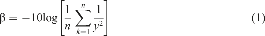
Flexural properties
Flexural properties of PLA-PVDF NFs-PLA interleave composite structure.
Optimization of process parameters
SN ratios for flexural properties of PLA-PVDF NFs-PLA interleave composite structure.
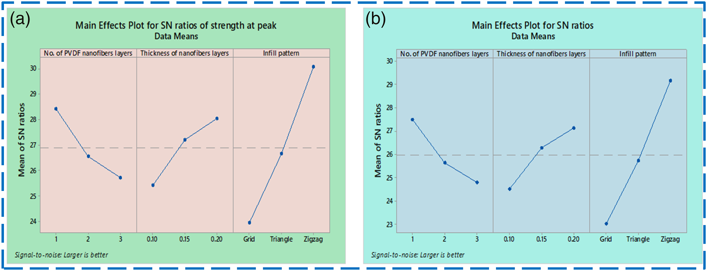
Main effect of SN ratios of (a) flexural strength at peak (b) flexural strength at the break for PLA-PVDF NFs-PLA interleave composite structure.
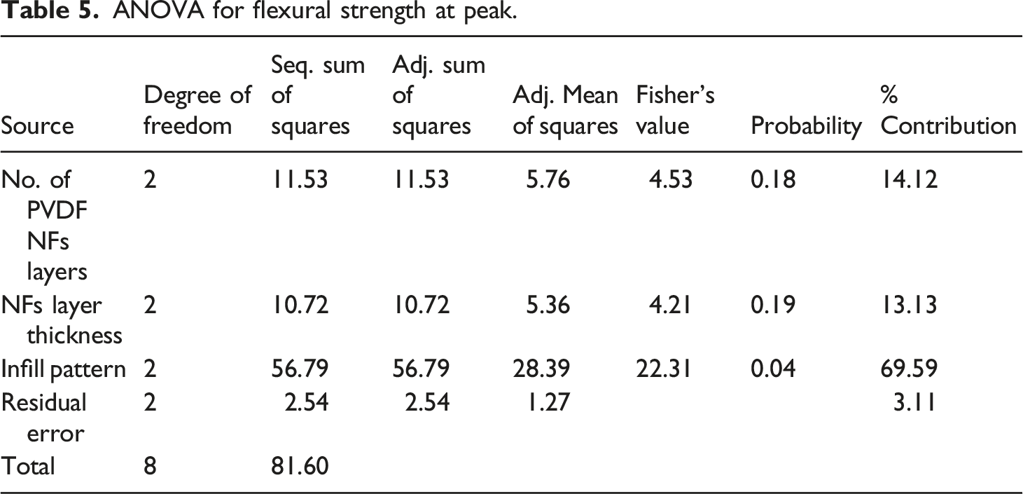
ANOVA for flexural strength at peak.
SN ratios for flexural strength at peak of PLA-PVDF NFs-PLA interleave composite structure.

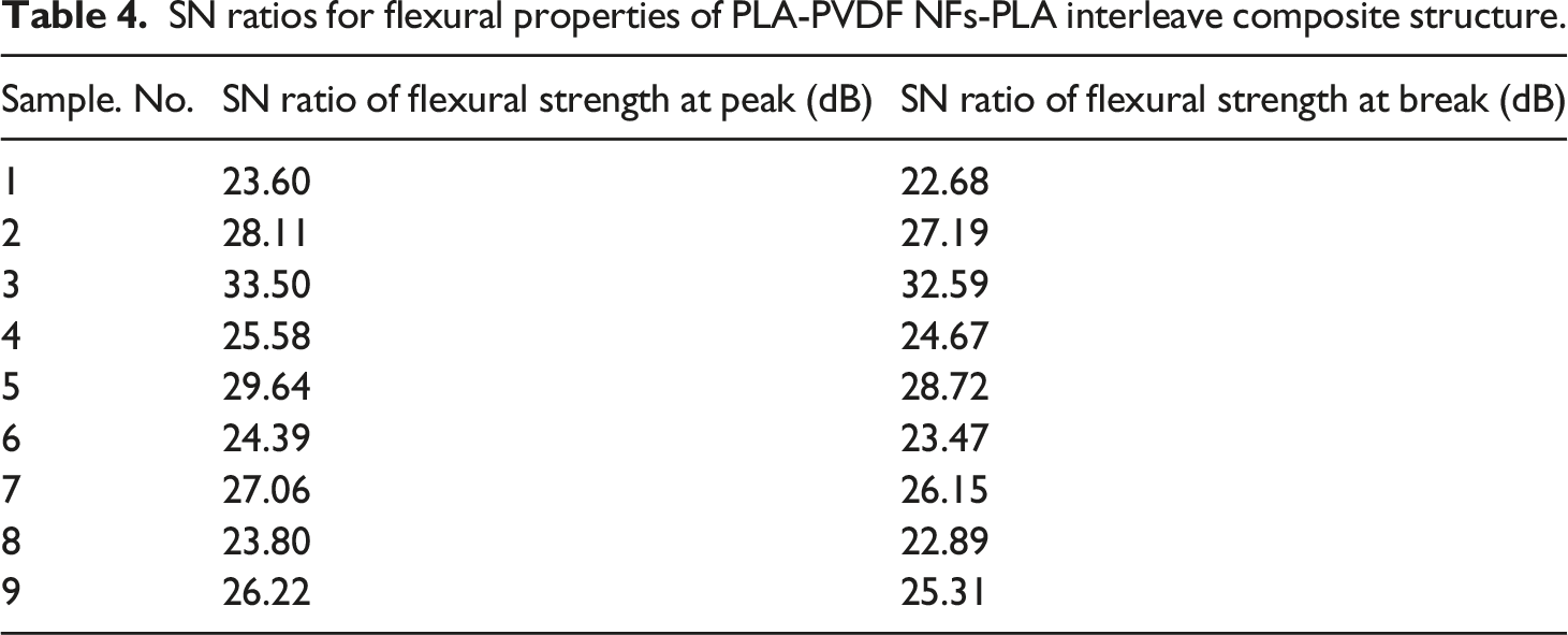
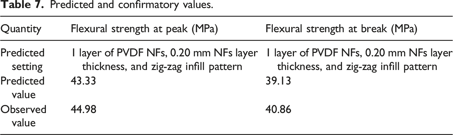
The evaluation of optimized mechanical properties can be done by calculating SN ratios. The optimum values can be found in equation (2).
β = SN ratio’s mean for flexural strength at the peak of all samples
βA1 = SN ratio for the number of layers of PVDF NFs at level 1
βB3 = SN ratio for the NFs layer thickness at level 3
βC3 = SN ratio for infill pattern at level 3
From evaluations of Tables 4–6:
β = 26.88 dB, βA1= 28.41 dB, βB3= 28.04 dB, βC1= 30.07 dB
αopt = 26.88 + (28.41– 26.88) + (28.04 – 26.88) + (30.07– 26.88)
αopt = 32.76 dB
Equation (3) can be used for calculating the SN ratio’s optimum value for flexural strength at peak.
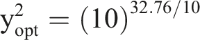
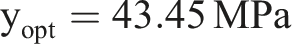
Predicted and confirmatory values.
SEM analysis
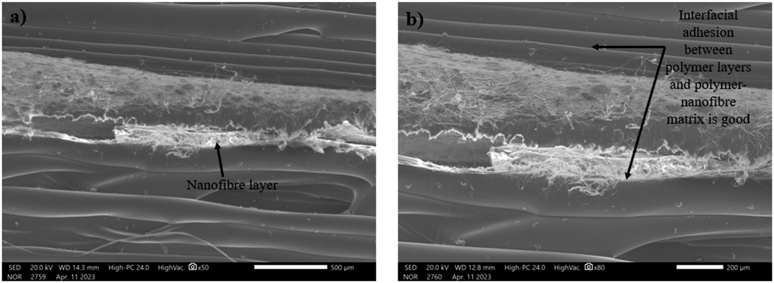
Figures 5 and 6 represent the SEM analysis of sample 1 (1 layer of PVDF NFs, 0.10 mm NFs layer thickness, and Grid infill pattern), and sample 3 (1 layer of PVDF NFs, 0.20 mm NFs layer thickness, and Zig-zag infill pattern) respectively, based upon Tables 1 and 2. The gaps or voids present inside sample 1 are more, which lowers the composite specimen’s strength, and the mechanical properties got affected. The better interfacial adhesion mechanism involves the combination of physical and chemical interactions which consists of intermolecular forces, hydrogen bonding, and mechanical interlocking between two materials due to surface features.53,54 Sample 3 possessed better mechanical properties due to improved adhesion between the layers of polymer composites at their interfaces and polymer matrix with NFs composite. The mechanical properties got impacted due to the formation of the internal structure during printing.
55
SEM images of sample 1 at a magnification of (a) ×50 (b) ×80. SEM images of sample 3 at a magnification of (a) ×50 (b) ×80.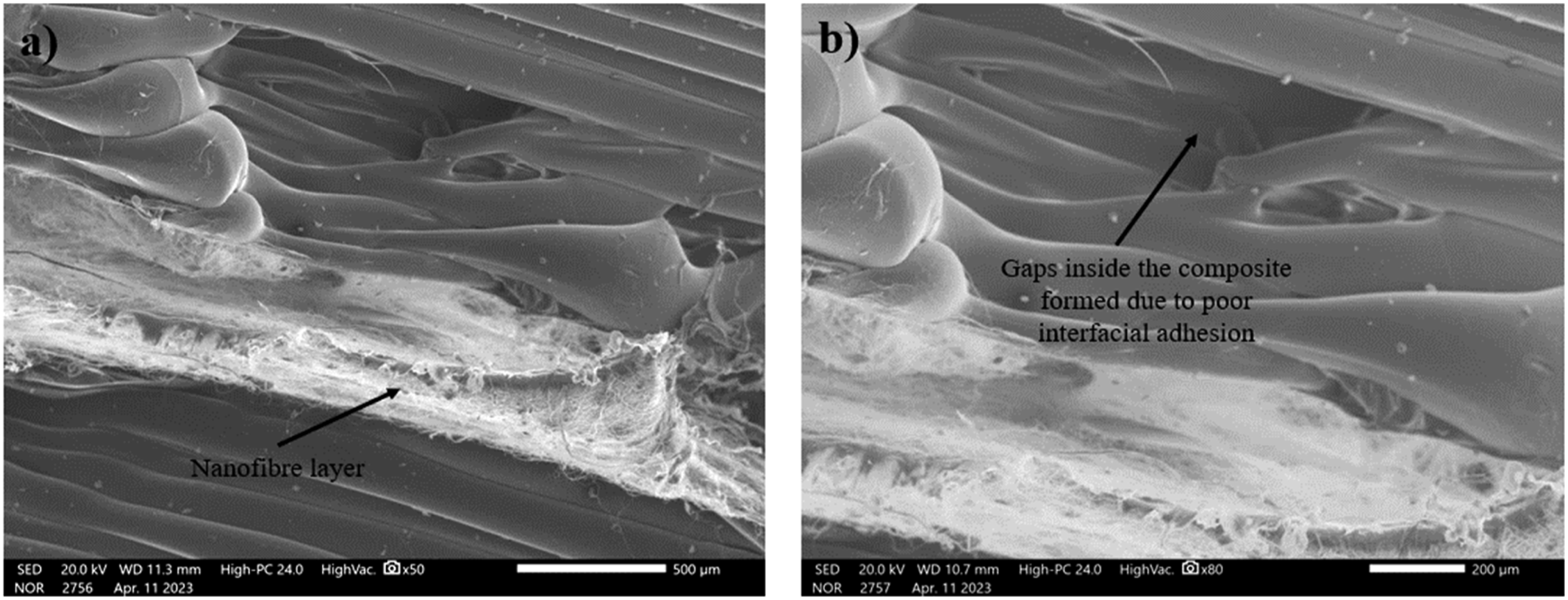
Energy dispersive spectroscopy analysis
Figure 7(a) and (b) show the energy dispersive spectroscopy (EDS) analysis of sample 1 and sample 3. The presence of fluorine and better adhesion may be responsible for better flexural properties as the PVDF NFs possessed better elongation properties.
56
EDS of (a) sample 1 and (b) sample 3.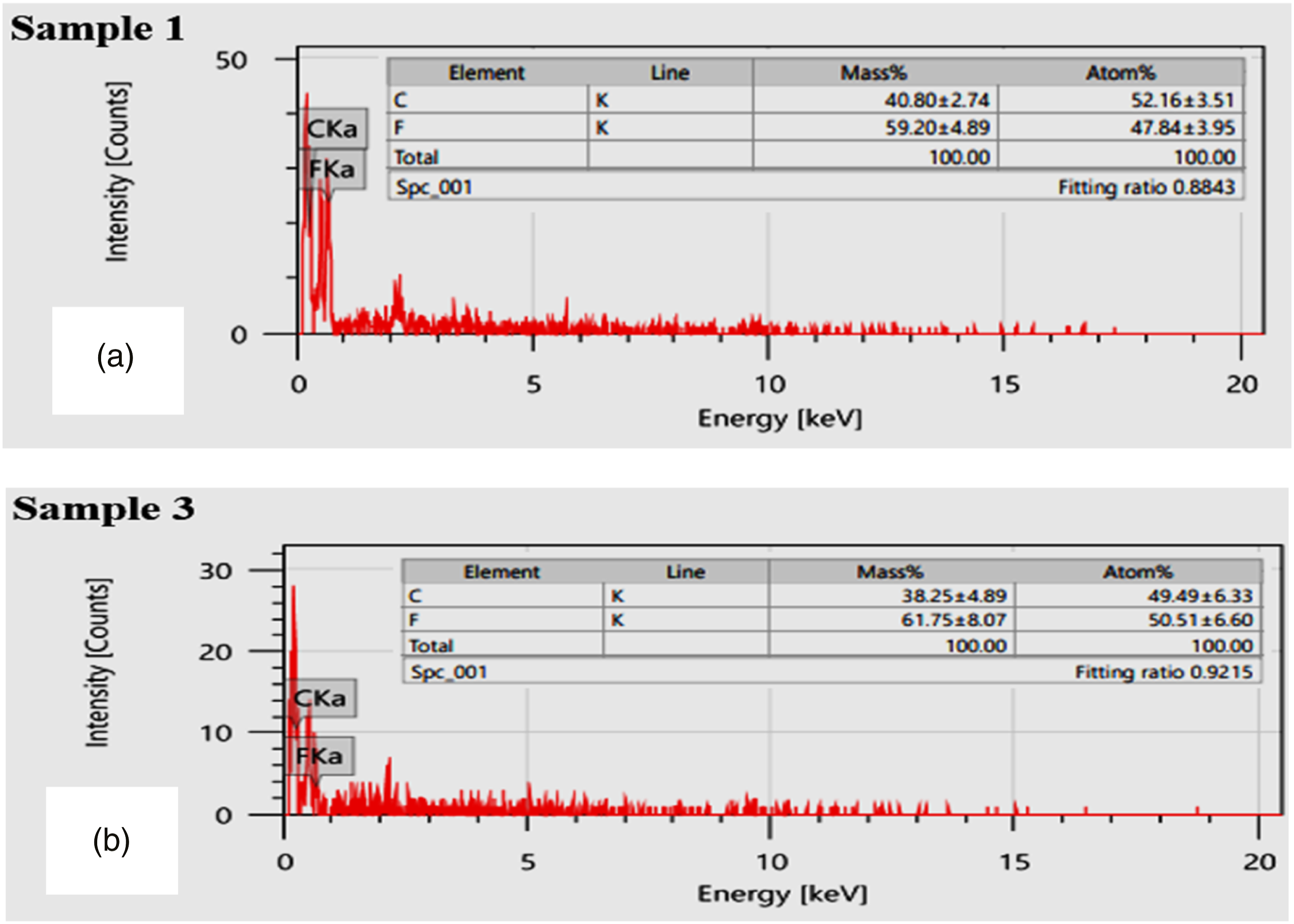
Roughness and porosity profiles
Figure 8(a) shows the rendered surface of the fractured region of sample 1 and sample 3 underdone the flexural loading. The stretching of the PVDF NFs is one the reason that it increasing the irregularities in fracture region of sample 3, tends to more flexural strength. Figure 8(b) show the porosity profile (of fractured region) of sample 1 and sample 3. The maximum porosity observed for sample 1 is 13.34% which may be responsible for lowering the strength of the composite structure which directly impacts the mechanical properties. The porosity observed for sample 3 is 11.81%. The better adhesion and lower porosity improved the mechanical properties. (a) Rendered profile of the fractures region and (b) porosity observations for sample 1 and sample 3.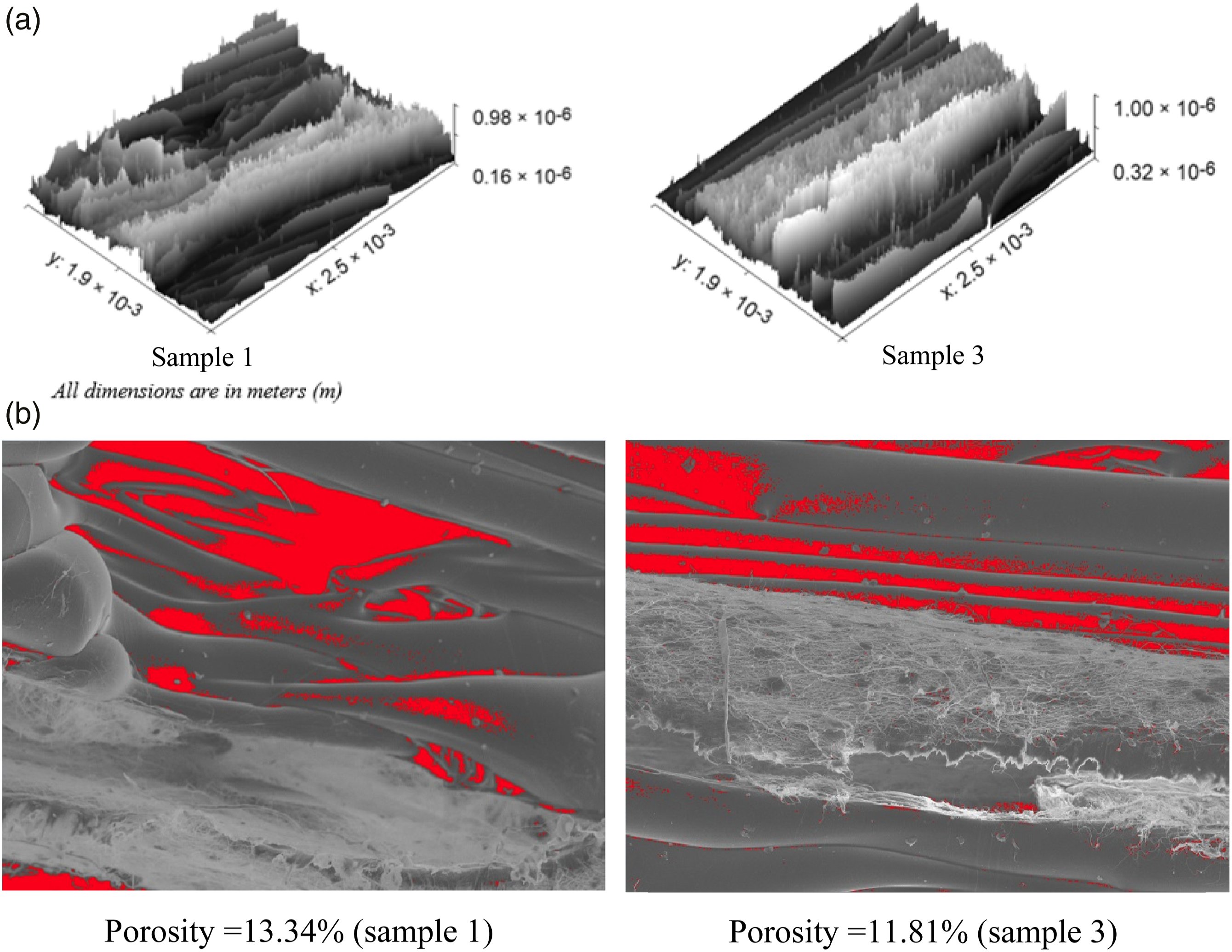
XRD analysis
Figure 9 shows the spectra of XRD for sample 1 (1 layer of NFs, 0.10 mm NFs layer thickness, and grid infill pattern) and sample 3 (1 layer of NFs, 0.20 mm NFs layer thickness, and Zig-zag infill pattern) for the PLA-PVDF NFs-PLA composite structures. The samples having a zig-zag pattern contain more interfacial area as compared to the sample containing a grid pattern which also may be the reason responsible for shifting in peaks. The shifting of 2θ angles also may be a result due to solvent-induced bonding interaction between PLA with PVDF NFs. The crystallinity of sample 3 is also better due to which the arranged molecular chain formed inside the composite with the inclusion of PVDF NFs. The higher crystallinity may lead to enhanced mechanical properties of the manufactured composite specimens.
57
Spectra of XRD for sample 1 and sample 3.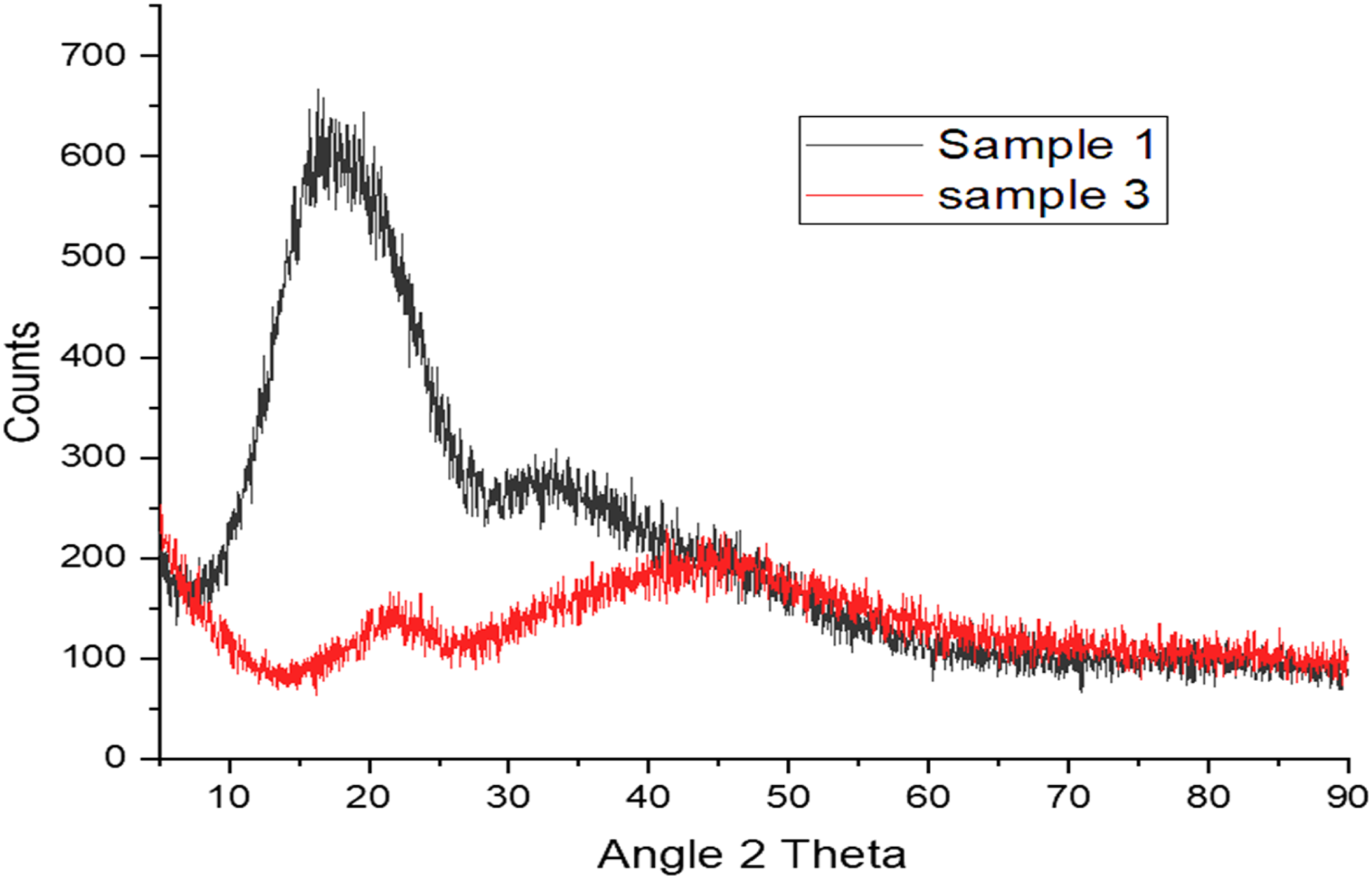
FTIR analysis
Figure 10 shows the spectra of FTIR for sample 1 and sample 3 of the PLA-PVDF NFs-PLA interleave composite structure. Spectra of FTIR for sample 1 and sample 3.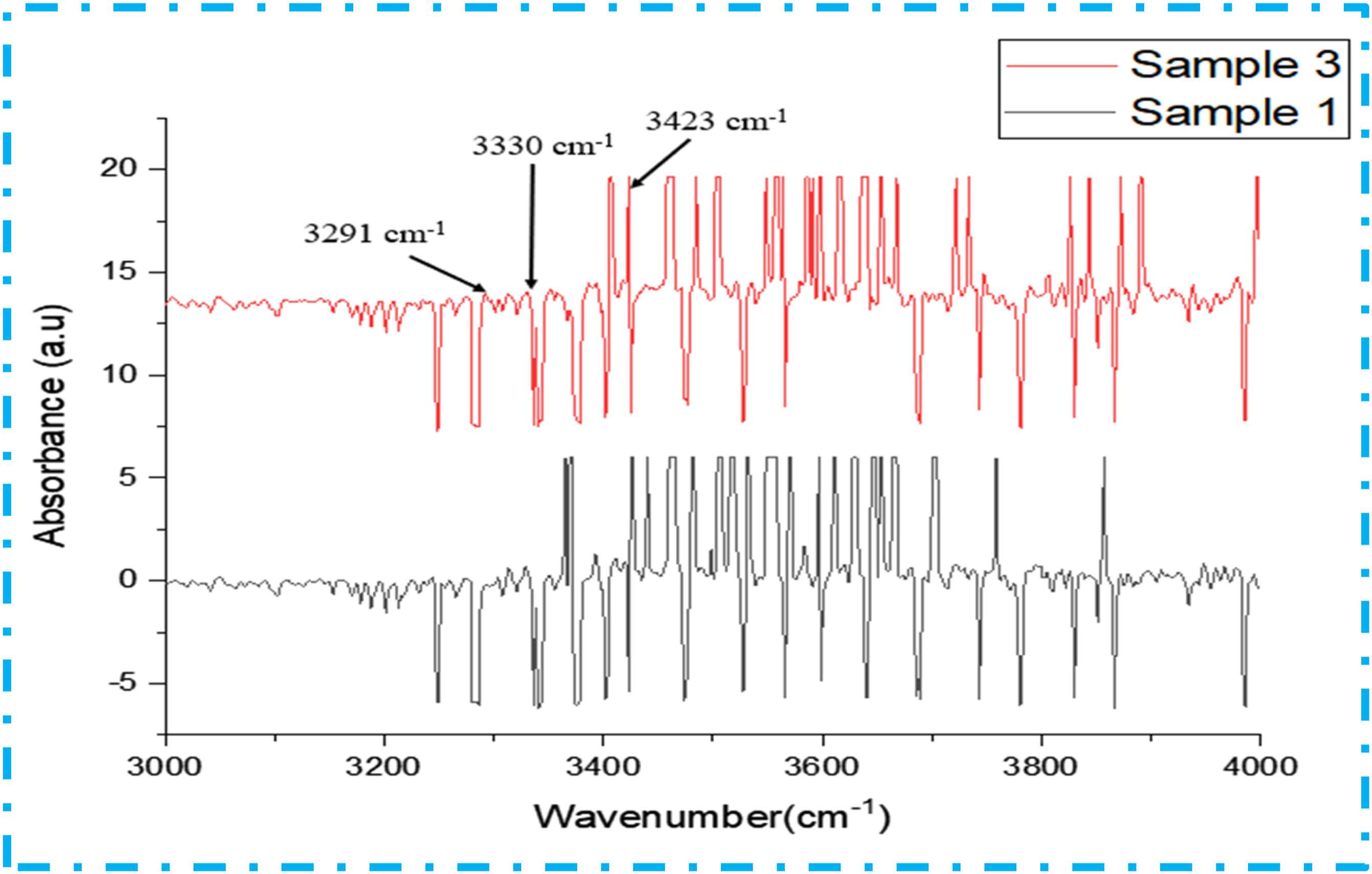
The functional groups were determined for these specimens in the 3000–4000 cm−1 range. The functional groups contained in a sample can be identified by comparing the detected peaks with IR reference spectra. The strong C-H stretching was observed at a wavenumber of 3291 cm−1 and sharp peaks with strong intermolecular bonded O-H stretching were observed at 3423 cm−1. The presence of materials is confirmed by the observed functional groups present in the chemical analysis of composite samples.
V-I and V-R characteristics
The V-I and V-R characteristics of PLA-PVDF NFs-PLA interleave composite structures as shown in Figure 11. As the PLA is an amorphous material and non-conductive but the PVDF is conductive. So, the electrical properties got affected by the incorporation of PVDF NFs. The finding of the study suggests that composite structures primed by higher mat thickness and zig-zag infill pattern have resulted in higher electrical resistance and better shape memory effect. However, increasing the voltage in the composite structure having higher mat thickness with a zig-zag fill pattern has resulted in a higher resistance drop (Figure 11). (a) V-I (b) V-R characteristics of sample 1 and sample 3.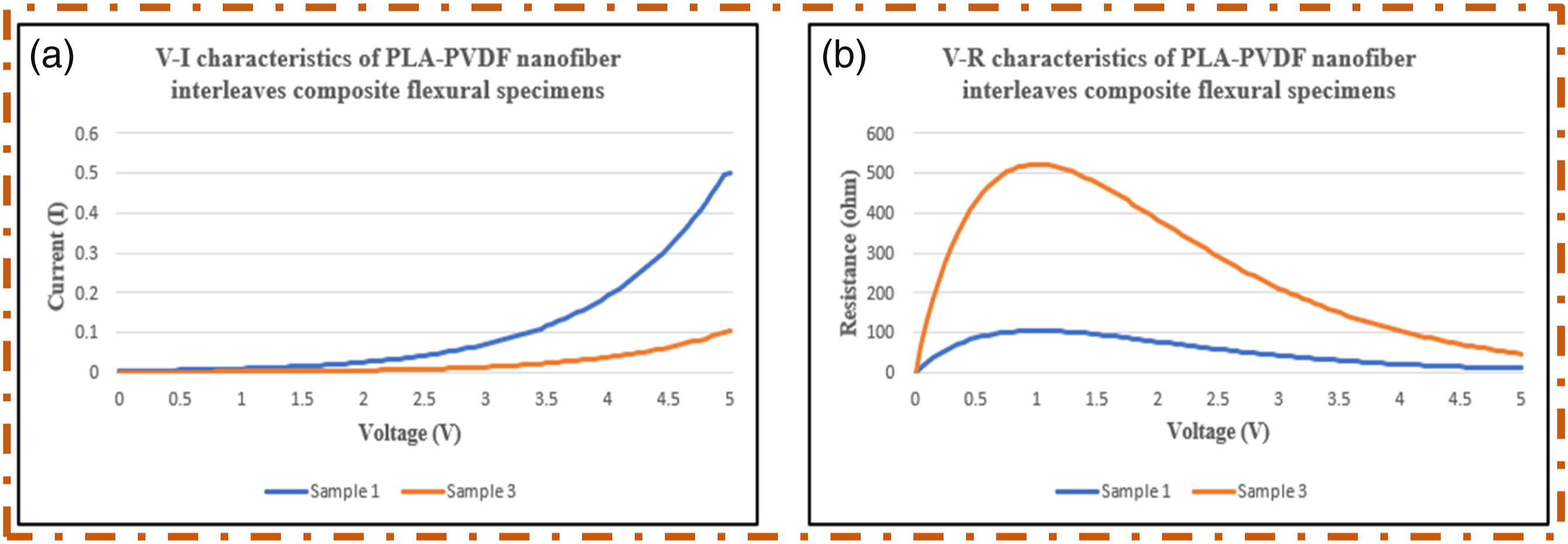
Generally, the phase changes occur due to thermal stimulus in PLA to regain their original shape and V-I or V-R characteristics analyzed the thermal conductivity under thermal stimulus. 58 During the resistive heating, the energy consumption and heating efficiency can be analyzed and resistive heating supports to improve the performance of shape recovery of PLA. The shape recovery efficiency of PLA can be increased by using that knowledge to design heating circuits or systems that can give the required amount of thermal energy efficiently.
Shape memory analysis
Figure 12(a) shows the structure of the infill patterns inside the PLA-PVDF NFs-PLA interleave composite structure. (a) Schematic of the sample for shape memory analysis and (b) shape memory behaviour of sample 1 and sample 3.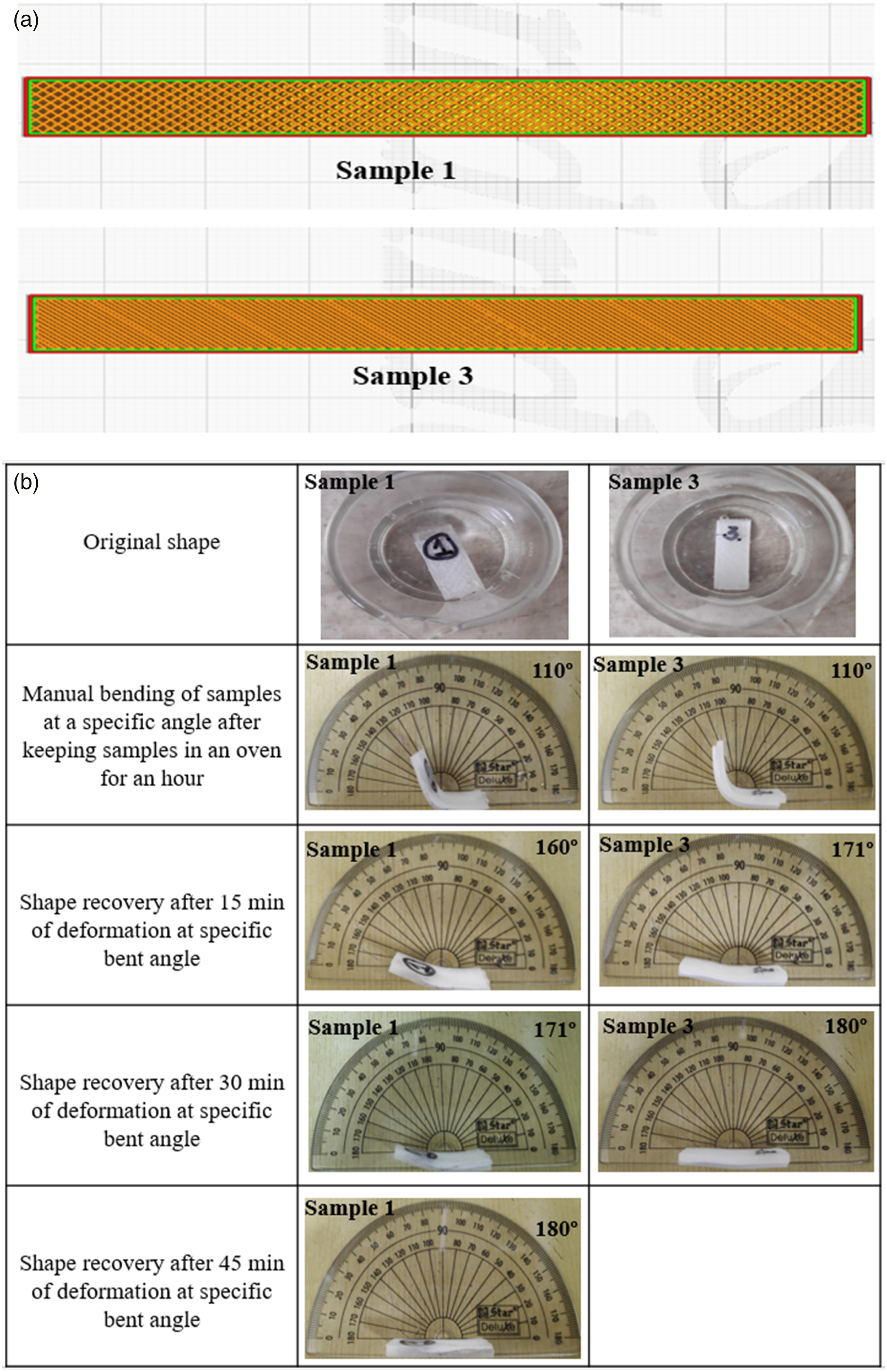
In the first stage, sample 1 (1 layer of PVDF NFs, 0.10 mm NFs layer thickness, and grid infill pattern) and sample 3 (1 layer, 0.20 mm NFs layer thickness, and zig-zag infill pattern) were kept in the oven at 70°C for 1 hour. Due to the thermal stimuli, the samples become flexible. Both samples were bent at a 70° angle and cooled down for 5 min to room temperature to attain the fixed shape at a deformed angle. After attaining the deformed shape, both composite structures were placed in the same temperature conditions in an oven and the shape-changing behaviour was observed after a certain time period continuously as shown in Figure 12(b). Both the samples attained their original position even after deformation but the Sample 3 (contains zig-zag pattern) regained its original position faster than sample 1 (contains grid pattern). The grid pattern consists of large gaps between the layers as compared to the zig-zag pattern. The lines printed in a zig-zag pattern are also continuous and in one direction which may push another continuous layer to retain the original shape and become the reason for retaining the original shape in lesser time being exposed to thermal stimuli.
Conclusions
The best setting parameters resulting from parametric optimization for manufacturing of PLA-PVDF NFs-PLA interleave composite structures are the combination of 1 layer of PVDF NFs, 0.20 mm NFs layers thickness, and a zig-zag infill pattern. An improvement of 6.47% flexural strength was observed in PLA-PVDF NFs-PLA interleave composite structures as compared to the neat PLA structure. The finding VI and VR analysis of composite structures primed by higher mat thickness and zig-zag infill pattern have resulted in higher electrical resistance and better shape memory effect. However, increasing the voltage in the composite structure having higher mat thickness with zig-zag fill pattern have resulted in higher resistance drop. The PVDF NFs influenced the flexibility of the composite structure and the PLA-PVDF NFs- PLA interleave composite structure showed better shape memory performance under thermal stimulus. The good results of shape memory performance was resulted for PLA-PVDF NFs-PLA structures have shown that the composite structures are the potential candidates to be used for smart grippers and smart actuators applications.
Footnotes
Declaration of conflicting interests
The author(s) declared no potential conflicts of interest with respect to the research, authorship, and/or publication of this article.
Funding
The author(s) received no financial support for the research, authorship, and/or publication of this article.