
Abstract
The pursuit of a renewable and recyclable material to reduce carbon footprint is the need of the hour for a safe and secure future of flora and fauna. This study explores the reinforcement potential of pre-treated recycled nylon fiber (NF) with CaCl2, NaOH and silane in a polypropylene (PP) matrix. Silane coating over the fiber surface was confirmed from FTIR and surface morphology. Interfacial interactions among NF and PP were further strengthened by adding nano-structured cetrimonium bromide (CTAB) treated fly ash (FA). A positive hybridization effect of FA was observed on such hybrid composites, apparent from an increment of ∼29% in tensile, ∼49% in flexural, and ∼970% in notched Izod impact strength. FE-SEM analysis showed good dispersion and distribution of reinforcements into the base matrix, establishing excellent interfacial adhesion. DSC analysis showed an increase in crystallization temperature (∼125°C) and a decrease in melting temperature of all the composites, while TGA confirms a reduction in the activation energy of all the composites.
Introduction
The adoption of polymeric composite materials in all sectors of the industries is increasing at an accelerated pace.1–4 In this regard, last few decades have seen enormous increment in the development of short fiber reinforced polymer composites. High-strength short fibers such as carbon,5,6 aramid, 7 and glass 8 were used by various industries/researchers earlier for reinforcing thermoplastic polymers.9,10 These short fibers are deployed for the fabrication of automobile parts, aerospace applications, high strength casing for electronic gadgets, construction, and many more.11,12 However, strength of the composite materials fabricated after the reinforcement of these fibers depends on the properties of the fiber and interfacial interaction at the interface. For instance, NF, which possesses high strength, high modulus and excellent impact/toughness properties, is currently in use in the various defense, aerospace, sporting, and packaging industry.11,12 Likewise, PP which is a commodity plastic, is used for making the plastic raffia bags.
Additionally, the share percentage of PP has been increased enormously into the automobile sector. PP, possessed moderate mechanical and hinge properties along with density lesser than 1 g/cm2. 13 Due to the lack of required mechanical properties, all the automobile parts cannot be fabricated using pristine PP. Hence, researchers suggested for higher tensile, flexural and impact strength polymer. PP must be reinforced with a strong reinforcement medium to accomplish these properties. In this regard, Quazi TH Shubhra et al 14 reviewed mechanical properties of polypropylene composites reinforced with various short fibers/particulate reinforcements. Authors reported advantages and disadavantages of various type of fillers and their particular uses. 14 However, short glass fiber, basalt fiber, and natural fiber-reinforced composites showed a promising improvement in tensile and flexural properties. However, it exhibited decreased impact strength due to the brittle nature of reinforcements. Hence, NF could be the best answer for reinforcing the thermoplastic polymers. Also, incorporating NF may extend the anti-cutting, anti-tearing, and wearing properties of the fabricated automobile component.
Another major problem associated with composite fabrication is the presence of voids and defects in a short fiber reinforced polymer composite. Many researchers have well reported that the use of nano/micro particulate filler and reinforcement may decrease these defects. It was presumed that the right concentration of these particles fills the voids and helps in the manufacturing of defect-free composite. Also, nanoparticles may help to decrease the interfacial gap among reinforcing fiber and polymer matrices. Hence, the fabrication of a hybrid composite may be a logical step ahead.
Furthermore, many nanoparticles such as TiO2, CNT, graphene, and hardwood are available commercially for the same purpose. Nonetheless, some studies also reported using FA particles with natural/synthetic fiber to fabricate hybrid composite. FA, which is reach in inorganic oxides such as SiO2 and Al2O3, might provide an environmental and manufacturing cost benign.
NF, a polyamide, possessed a high degree of orientation, crystallinity, and rigid molecular chain. Also, a smooth surface and the absence of many active groups on the fiber surface make them highly incompatible against a polymer matrix.15–18 In this regard, researchers have reported using various physical and chemical treatments to enhance the interfacial adhesion between NF/AF (aramid fiber) and polymer matrix.
19
The most frequent methods used by researcher for increasing compatibility of NF with polymer matrix are Lewis acid modification, graft polymerization, plasma with ultrasonic treatments, ultrasonic radiation.20–28 The basic principle behind the Lewis acid treatment of the NF was to interact the lone pair of the acid with the Lewis base (polyamide bond) of the molecular chain on the fiber surface. It was presumed that interaction among these groups might break the intermolecular hydrogen bond held by these amide groups. However, this activity on the fiber surface resulted in the decline in crystallinity and improvement in the roughness of the fiber surface.29–31 Expanding the research, Zhang et al
32
and Yang et al
33
prepared PA6/CaCl2/HCOOH solution to achieve CaCl2 complex bond with the carbonyl group of amide present in PA6. A probable interaction between CaCl2 and amide linkage has been provided in Scheme 1. Furthermore, Li et al
35
treated AF in an ethanol and CaCl2 solution keeping the ratio 95:5 (w/w) for different time periods. Data reported by the authors showed that with the increase in treatment time, there was a decrease in the Rupture strength of the AF exhibited. Illustration of treatment of NF with CaCl2, NaOH, and APTES
34
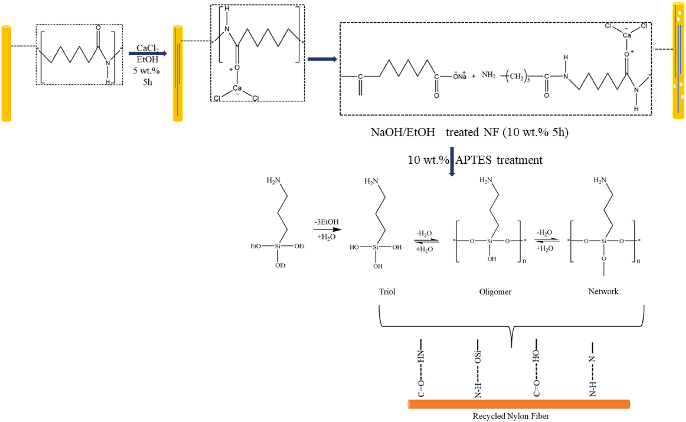
Treatment with CaCl2 increases the surface roughness and provides only physical interaction with the polymer matrix. To develop an excellent interfacial adhesion, the surface of the NF must be chemically active and interact with the other functional groups of the polymer matrix. In this regard, Ti3C2 Mxene nano sheet bounded to AF were reinforced in the PP matrix to fabricate composites. Both Ti3C2 and NF were etched with hydrofluoric acid and phosphoric acid before bounding to each other. 36 In another study, Maity et al used fluorinated AF for reinforcing PP and reported increased mechanical and thermal properties of the composites after using fluorinated AF as reinforcement. Likewise, Monier et al and Chatzi et al used NaOH treated AF for increasing surface activity of the AF by breaking hydrogen bond among aromatic amide groups.37,38 Furthermore, many researchers have established and used the use of silanes (silanol after hydrolysis) to interact with oxygen-containing reinforcement and another end with a hydrophobic polymer matrix to form a crosslink. For instance, Lin et al 9 used NaOH and CaCl2 to increase surface roughness and separate methacryloxypropyltrimethoxy silane coating on AF surface to improve interfacial interaction of the treated fiber with the base rubber matrix. Likewise, Thomas et al39,40 used nylon 6 of 0.03, 0.25, and 0.5 mm diameter to reinforce Styrene-maleic anhydride (SMA)-grafted PP and HDPE. Authors reported that the composite with least diameter of nylon fiber possessed highest tensile strength of ∼40 MPa 39 for PP reinforced composites. For HDPE reinforced composites authors analyzed flow behavior of the composites using capillary rheometer and a torque rheometer. Findings from the nylon-6 fiber reinforced (SMA)-grafted HDPE composite shows that fiber content makes composites pseudoplastic and processing of the composites did not affect adversely at higher shear rates. 40
The experimental section n the current srtudy first develops NaOH and CaCl2 treated NF followed by APTES coating to reinforce base matrix BM. Another reinforcement, FA, was CTAB treated into a high-energy planetary ball milling in an ethyl acetate medium down to a size of less than 1 µm. 13 Base matrix was modified by incorporating 10, and 5 wt.% of SEBS and SEBS-g-MA to the PP already reported in our earlier study.13,41,42 It was believed that APTES treated NF contains propyl and amine (-NH2) group, which will interact with the molecular chains and MAH group of BM, respectively. Interaction among -NH2 and -MAH probably will lead to new amide linkage increasing the crosslink into the composite. PP, BM, and composites specimens were fabricated through melt extrusion and injection molding. Various testing and characterization such as mechanical properties via UTM and impact tester, microstructural through ATR-IR and FE-SEM, thermal properties via TGA and DSC have been carried out as a part of the investigation.
Use of discarded nylon fiber ropes/packaging material (in the form of rope) is still one of the biggest environmental concern globally. Utilization of recycled nylon fiber, used currently for packaging applications, instead of aramid fiber to reinforce a base matix has been explained in the studies. Likewise, addition of sub-micron particles of cationic surfactant treated fly ash to these composites may strengthen them further. After the fabrication of these hybrid composites one can expect meticulous use of wastes generated from thermal power plant and packaging industry. The above mentioned studies have attempted to present recycled nylon fiber as an optional reinforcement material into the polymeric matrix.
Materials and methods
Materials
Reliance Industries Pvt. Ltd., India, supplied PP homopolymer under the product name Repol H110 MA. The procured PP possessed 0.908 g/cm3 of density and 11 g/min of MFI (weight of 2.16 kg at 230°C). SEBS, with trade name of Kraton G1651 H, and with styrene to rubber ratio 33:67 (w/w) and a specific gravity of 0.91 g/cm3 was purchased from the Kraton Polymers, USA. The compatibilizer, SEBS-g-MA, was procured from the DzBh new materials, China under the product name Beiwa® 901, with a styrene to rubber ratio of 30:70, density of 0.96 g/cm3, MFI of 43 g/min (weight of 5 kg at 200°C). FA under the product name of FillitTM500, (particle size 5–500 µm and density 0.80-0.83 gm/cm3), was supplied by the Petra Build Care Product Pvt. Ltd, India. Sisco Research Laboratories Pvt. Ltd., India supplied CTAB with a pH and melting point of 5–7 and 249–253°C. NF ropes used in the current work and preowned for packaging applications were collected after the primary job has been furnished. Procured NF from the ropes recorded a tensile strength and modulus of 70 MPa and 1.6 GPa and notched izod impact strength of 9.11 kJ/m2. Obtained NF also demonstrated a flexural strength and modulus of 140 MPa and 3.5 GPa. Also, FE-SEM analysis of the NF demonstrated an average diameter of ∼12 µm (Figure 1). After the NaOH-CaCl2 and APTES treatment NFs were chopped in a fiber length of 3–4 mm. (a) Diameter and surface morphology of the (b) untreated and (c) treated NF.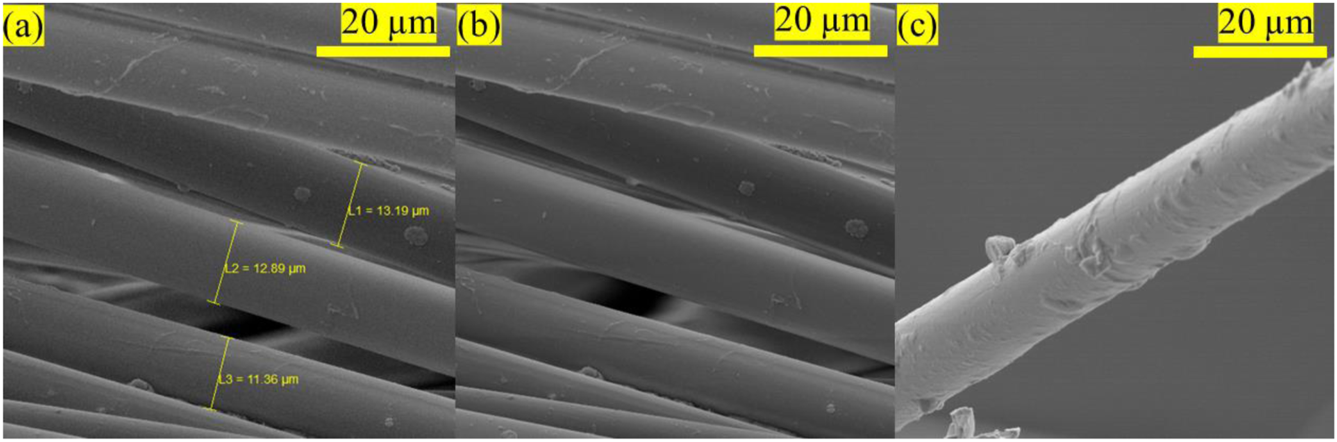
Reinforcing cetrimonium bromide treated nanostructured fly ash
Chemical activation of surface of FA with CTAB (6 wt.%) along with downsizing to <1 μm was achived using high-energy ball mill supplied by Retsch, Germany. After 8 h of milling at 250 rpm in a 250 mL ethylene acetate medium containing tungsten carbide balls FA was chemically activated and particles reduced to a downsize less than 1 µm.13,42 A 1:10, ratio of medium to tungsten carbide balls (10 mm diameter) was maintained throughout the milling process. Figure 2 is a schematic presentation of the milling process of the FA. High energy ball milling and chemical activation of FA.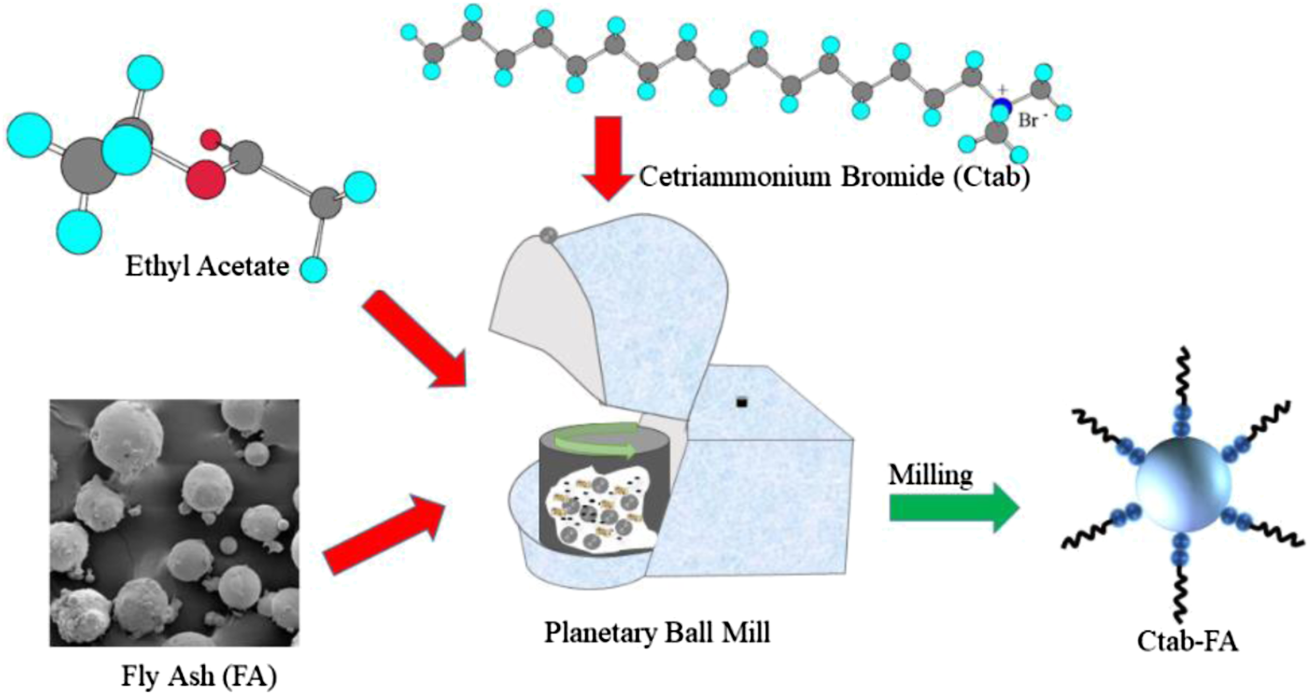
Reinforcing recycled nylon fiber
To remove any dirt and other earthy materials from NF surface, it was first washed under normal water. The water cleaned and dried NF were then ultrasonically treated in an acetone medium to launder it further for 1 h. The cleaned NF from acetone was then again washed 5 times with the help of deionized water. NF was then ready to be treated with calcium chloride solution which was achieved by dipping NF in a 5 wt.% CaCl2 aqueous solution with continuous stirring for 5 h. Thereafter, CaCl2 treated long-length NF fibers were transferred to a beaker containing 10 wt.% NaOH solution, and incubated for another 5 h at 65°C. Once the prescribed time period of 5 h with continuous stirring was achieved, R-NF were washed until a pH of 7 had been reached and then left for drying. Likewise, to coat APTES over the surface of R-NF, a solution of 10 wt.% of APTES was dissolved into a mixture of ethyl alcohol/DI water (90/10) for the hydrolysis of silane groups to respective silanols. In the next step, staples of CaCl2-NaOH treated R-NF fiber were placed in this solution for next 5 h. APTES coated fiber was then dried at 80°C for the next 6 h to remove any traces of moisture.
Preparation procedure
Preparation of base matrix, composite, and hybrid composite
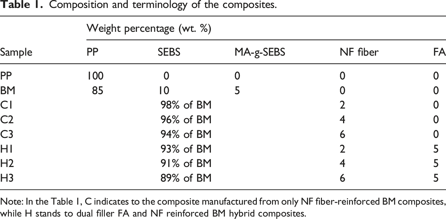
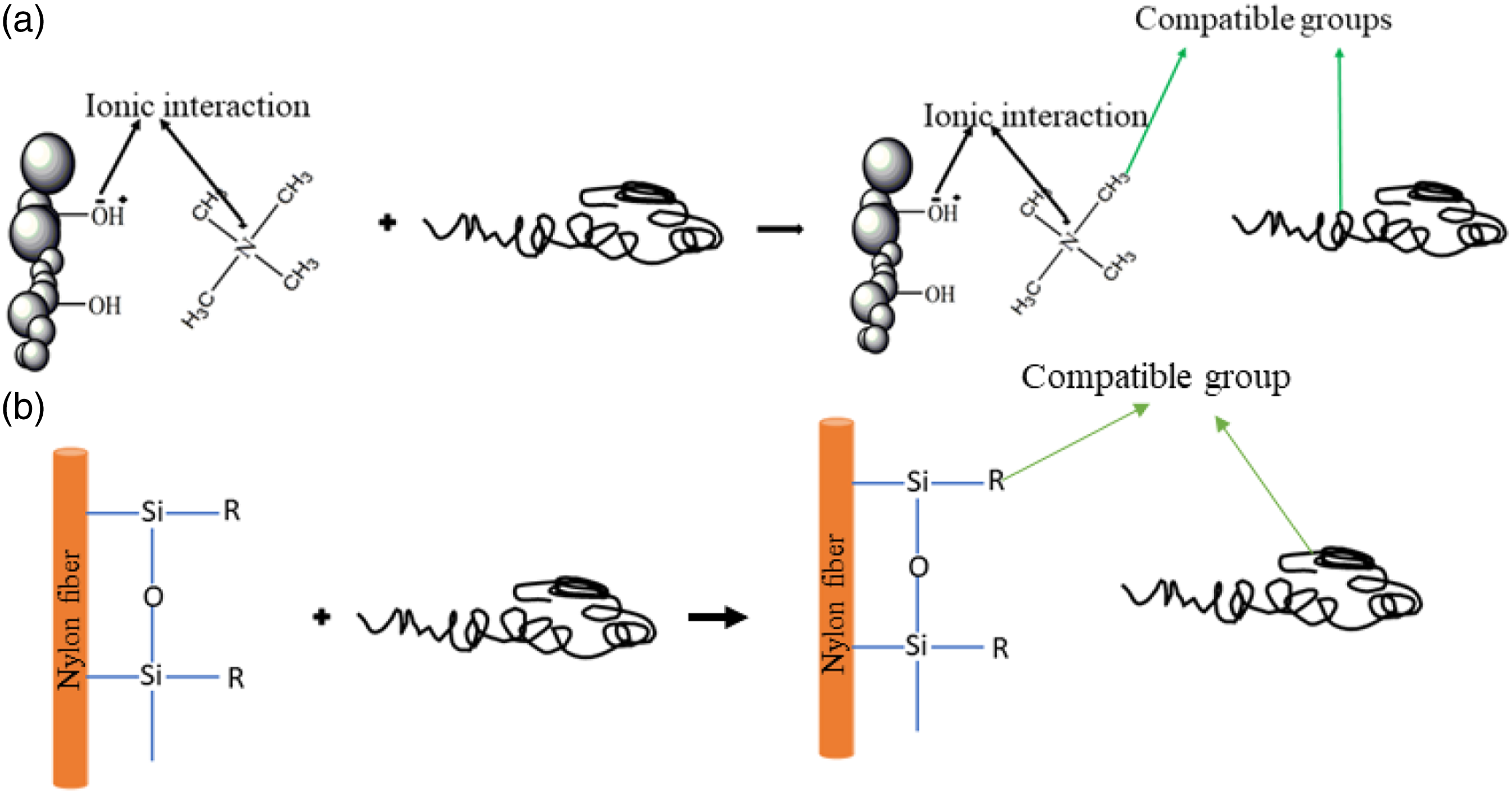
Figure 3 shows the process flow chart of the NF and FA treatment along with composite and hybrid composite fabrication. PP, FA, and R-NF were dried prior to processing to remove any traces of moisture at 80°C for 24 h. As a first step, for the preparation of BM was achieved by adding 85 wt.% of PP, 10 wt.% of SEBS, and 5 wt.% of SEBS-g-MA to the feeder of HAAKETM Rheomix miniCTW twin screw mixer (Make; ThermoFisher SCIENTIFIC) between 185-190°C at 10–50 rpm for 15 min. Likewise, for the fabrication of composites, 2, 4, and 6 wt.% of R-NF were slowly added to the melted mixture of BM separately for each composite. However, for hybrid composites preparation, 5 wt.% of FA was initially added to the melt mixture of BM prior to the addition of R-NF. It was supposed that the slow inclusion of FA to the BM provides resistance against the agglomeration and aggregation of the FA into the composites. The compositions and respective terminology of various samples are elaborated in Table1. Figure 4 is a schematic representation of the any interaction between NF, FA and BM. Process flow chart of the set of experiments. Composition and terminology of the composites. Note: In the Table 1, C indicates to the composite manufactured from only NF fiber-reinforced BM composites, while H stands to dual filler FA and NF reinforced BM hybrid composites. Interaction between the (a) cationic surfactant treated fly ash to the BM and (b) silane treated nylon fiber to the BM.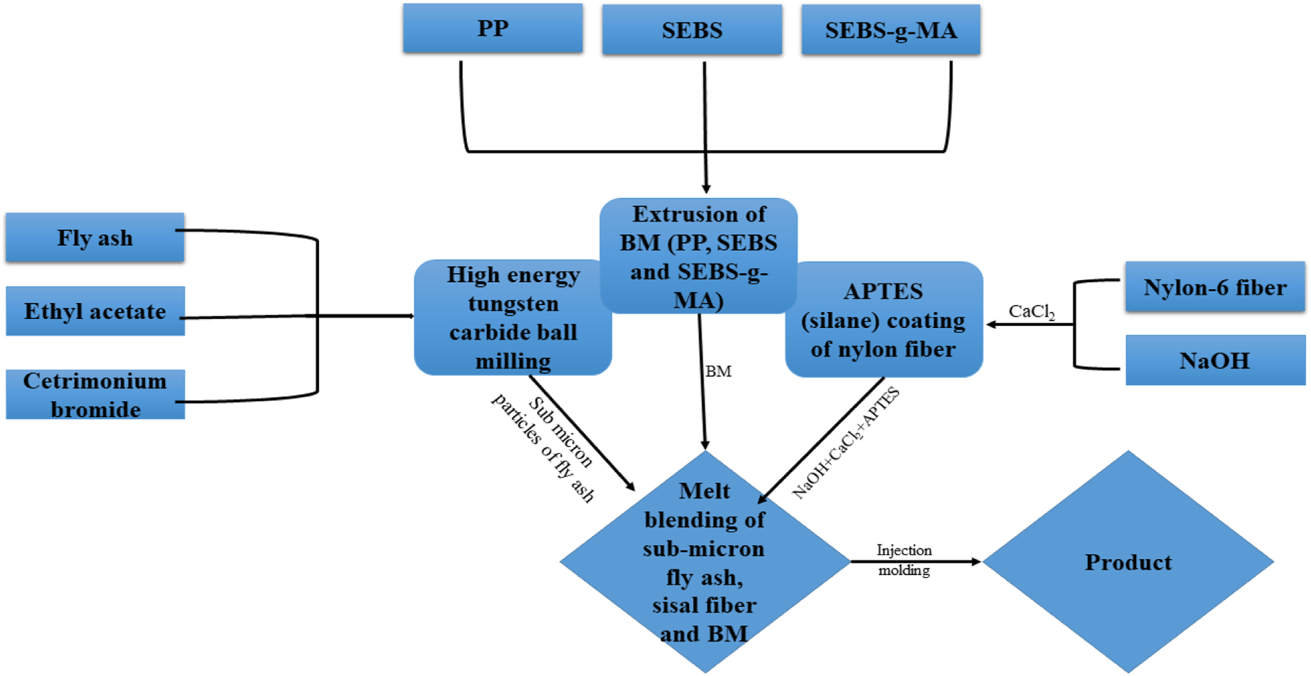
Preparation of testing specimens of base matrix, composites, and hybrid composites
Fabricated BM, composites, and hybrid composites received from Rheomix were in the form of lumps, which were then granulated for making the specimens via micro injection molding. Granules of each samples were first compounded in a micro-compounder HAAKETM MiniCTW (Make; ThermoFisher SCIENTIFIC) at ∼190°C and 50 rpm again, separately. Melt from the compounder transferred to the cylinder of HAAKE™ Minijet II micro injection molding uphold at 190°C. The plunger of this cylinder provided a 450 Pa pressure to push the melt mixture into the molds of various-shaped specimens placed in the HAAKE™ Minijet II micro injection molding machine.
Testing and characterization
Mechanical properties
ISO 527-2 43 and ISO 178:2019 44 standards were applied on a UTM (INSTRON 5 KN Model 3365) alongside a crosshead speed of 15 mm/min and 2 mm/min to assess the tensile and flexural properties, respectively (average of 5 samples) of all the samples. For estimating the impact properties, the Tinius Olsen impact tester was used to follow ISO 180 45 standard. A notch of 0.25 ± 0.05 mm at 45° was prepared in each of the 5 samples for impact testing.
Differential scanning calorimetry
DSC of all the samples were characterized in 2 heating and 1 cooling cycles starting from room temperature to 250°C (heating), 250°C to −60°C (cooling) and −60°C to 250°C heating), respectively at 5°C/min heating rate on a TA instrument (Discovery series 25) following ASTM D3418-15 standard.
46
Percentage crystallinity of the samples was calculated using the following equation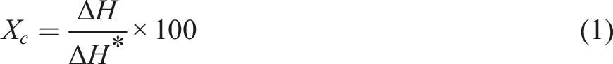
In the equation (1) X c , ∆H, and ∆H * represent the crystallinity, melting enthalpy of the samples, and melting enthalpy of the 100% crystalline PP. ∆H * for the 100% crystalline PP and NF is taken as 20747–49 and 190 J/g. 50 Also, dynamic mechanical thermal analysis was used to study the glass transition temperature of all the samples using ASTM D5576-00. 51
Morphological analysis
The surface morphology of gold-coated NF fiber and all the composites mounted on an aluminum stub were investigated using the Mira3 Tescan instrument at an acceleration voltage of 5 kV.
ATR-IR
The presence of various functional groups on NF/silane treated NF and formation of new bonds into the composites were confirmed by performing ATR-IR characterization on the samples within a range of 4000-500 cm−1 following ASTM D5576-00 standard 52 on a Perkin Elmer Spectrum 2 instrument.
Thermal degradation
10 mg of material from each sample were placed in an EXSTAR TG/DTA instrument under a Nitrogen (N2) atmosphere with a flow rate of 200 mL min−1. ASTM E1131-08 (2014) standard
53
was followed at a heating rate of 10°C min−1 to check the degradation behavior of samples within a temperature range of 23°C–800°C. The activation energy (Ea) for each of the samples was calculated using the Horowitz-Metzger model from given equation (2):
Where W
0
, W
f
, and W stand for initial, final, and weight at a given temperature T of the samples. θ implies for T-T
s
where T
s
is the degradation peak temperature. T
s
was selected from the DTG curve of each samples which implies the temperature of maximum degradation. Likewise, W
o
, W
f
and W was selected as 1 (100% weight of the material), 0.1 (10% weight of the material) and weight at temperature T. Where T varies from 5% weight loss to 75% weight loss. Thus activation energy can be calculated by plotting double logarithm of the reciprocal of the weight fraction (
Result and discussions
ATR-IR
Figure 5 is the plot of the transmittance versus wavenumber and demonstrates the ATR-IR spectra of the treated and untreated NF. The main characteristic peaks of the untreated NF have been designated at around 3315 (N-H), 1644 (C = O), and 1539 (N-H) cm−1 corresponding to II and I amide group due to the expansion vibration of these bands.9,35,54 Absorption peaks at 3315 and 1539 cm−1 were depleted due to the shifting of hydrogen bonding between N-H and C = O as a result of NF treatment with CaCl2 and NaOH. Also, COO− and calcium ion complexation formation probably happened at the NF surface (Scheme 1). Two new peaks at around 1719 and 1605 cm−1 appeared as a result of the development of COO− on the treated NF surface.9,35,54 Furthermore, grafting of APTES on the NF surface has been confirmed from the peaks corresponding to absorption bands at 1083, 1011, and 786 cm−1 appearing by cause of the presence of Si-O-Si, Si-O-CH3, Si-OH, and Si-C bonds.32,55 However, both treated and untreated NF demonstrated absorption peaks at 2925 and 2846 cm−1, corresponding to stretching vibration of -CH3 and -CH2. ATR-IR spectroscopy of untreated and treated NF.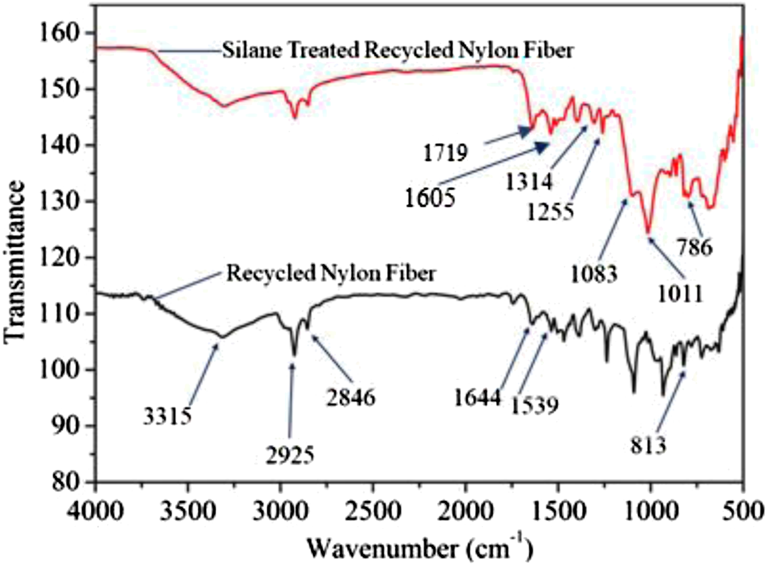
FE-SEM
The surface morphology of the treated and untreated NF is represented here from the FE-SEM analysis of the samples. The surface of short NF fibers is observed to be lustrous, smooth and free from any roughness (Figure 1(a) and (b)). However, dual treatment with CaCl2 and NaOH followed by APTES coating/grafting chemically activated the surface and developed some roughness (Figure 1(c)). It is presumed that these chemically activated and rough surfaces of the NF support in better interfacial adhesion and mechanical interlocking with the BM. The change in properties experienced due to the coating of NF with APTES was in line with the results reported in our previous work for the APTES treated sisal fiber. 56
Tensile properties
Tensile strength of the PP and BM reported in our previous studies as 30.61 and 27.82 MPa are considered here for comparative purpose13,41,42,56 (Figure 6(a)). A decrease in the tensile strength behavior of BM compared to the PP is attributable to the diminished tensile strength of the SEBS and SEBS-g-MA.
57
As expected, NF demonstrated greatest tensile strength of ∼70 MPa amongst all the samples. However, composites C, C1, C2, C3, H1, H2, and H3 recorded a tensile strength of 32.76, 32.60, 33.60, 38.25, 35.01, 36.69 and 39.40 MPa, respectively. All the composites reported tensile strength in between the tensile strength of BM and NF. Composites C which consists of only 5FE-SEMwt.% of the FA in the BM, demonstrated an increment of 7.02% in the tensile strength relative to pristine PP. The inclusion of FA to BM sufficiently strengthened the composite C. This noticeable increment confirms the strong interfacial adhesion between nanostructured CTAB treated FA and BM. The cationic head and tail of the CTAB surfactant apparently worked as a bridge between FA (negative zeta potential) and BM by forming polar interaction between CTAB and FA. Also, the small particle size (<1 µm) of the nano-structured FA possessed larger surface area for interactions compared to pristine FA. Likewise, composites C1, C2, and C3 also reported an enhancement of 6.5, 9.76, and 24.95% in tensile strength in comparison to PP, respectively. Probably, treatment of NF with CaCl2, NaOH followed by APTES increased the compatibility between NF and BM. Presumably, treatment with CaCl2 and NaOH solution resulted in complexation and hydrolysis of the amide linkages and on NF surface resulting in its surface activation. Hence, as a result, matrix-filler interfacial interaction enhanced, and the same can be confirmed from the improvement in mechanical properties with NF addition. The above-reported results were in good agreement with the data reported by Lin et al
9
where authors used CaCl2 and NaOH treated aramid fiber (aromatic polyamide) for reinforcing rubber matrix. In another study, polydopamine and anhydrous copper sulfate treated aramid fiber was used to reinforce epoxy matrix separately.58,59 Both the authors reported increased interfacial adhesion and enhanced mechanical properties of the composites due to the complexation (coordination bond) on the fiber surface. In this work, additional coating of NF with APTES promoted the surface activity, exposed area and interaction of the free NH2 group of the APTES with the MA group of the BM and establishment of the amide linkage between fiber and BM.41,56 However, the most outstanding tensile strength was shown by hybrid composites H1, H2, and H3 compared to their non-hybridized equivalents C1, C2, and C3. Here, H1, H2, and H3 led to increments of 14.37, 19.86, and 28.71% compared to pristine PP, respectively. The addition of nanostructured CTAB treated FA must have added advantage towards decreasing the NF-PP interfacial gap8,34 and filling of meso/micropores of the composites during manufacturing. This statement agrees with the investigation by Sumesh et al,
34
where the authors used pineapple fly ash to hybridize natural fiber polymer composite. The observed substantial increment in the tensile strength of the hybrid composites must have been the result of excellent load transmission from matrix to reinforcement. Nanostructured FA must have acted both as reinforcement and compatibilizer between NF and BM. Tensile stress and modulus of the PP, BM, NF and all the composites.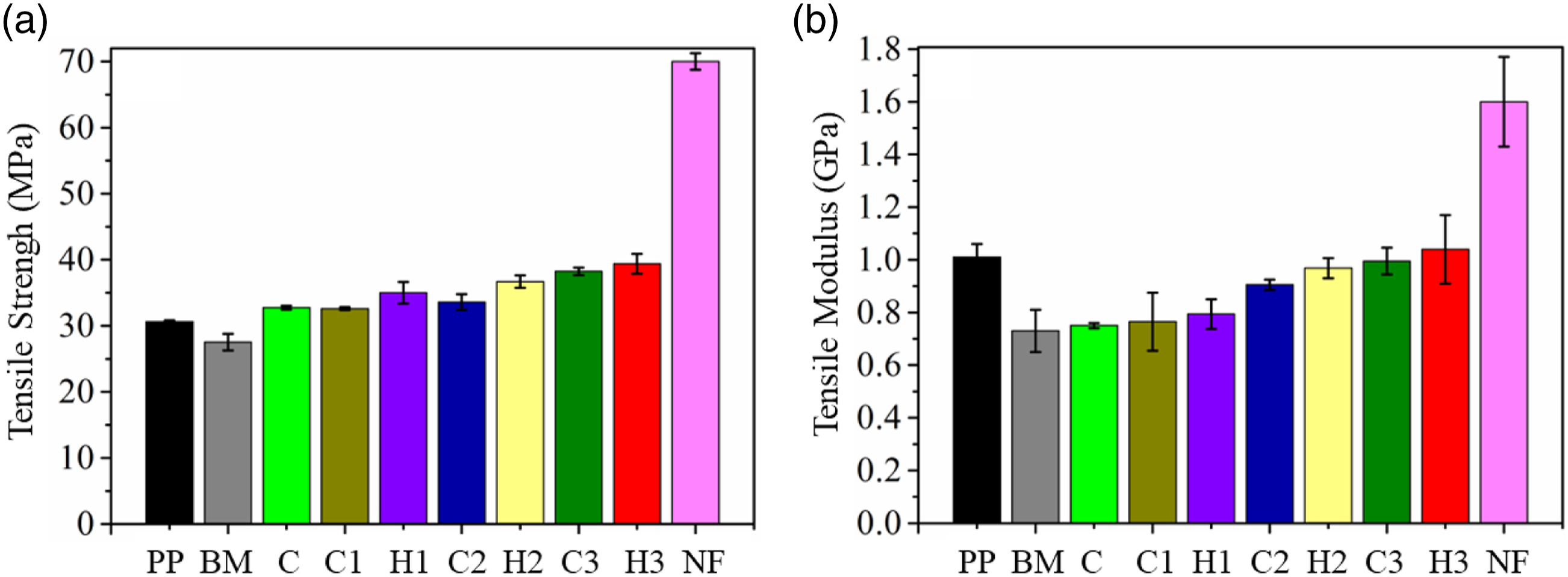
Tensile modulus of PP, BM, NF, C, C1, C2, C3, H1, H2 and H3 recorded a value of 1.01, 0.73, 1.6, 0.75, 0.76, 0.91, 0.99, 0.79, 0.96 and 1.04 GPa (Figure 6(b)). Although all the composites except H3 recorded tensile modulus lower than PP but the estimates still were still better than BM. Interestingly, all the composites recorded Youngs’s modulus in between the modulus of NF and BM. Furthermore, the above results also confirm a significant increase in the tensile strength of the composites over and above PP without compromising, with the flexibility. Interestingly, H3 possessed the highest Young’s modulus among all the samples and slightly more than compared to pristine PP. The increase in Young’s modulus of all the composites is related to excellent dispersion, distribution, and interaction of the reinforcements in the BM.
Flexural properties
The flexural properties of all the composites have been illustrated in Figure 7. Flexural strength of the samples, PP, BM, NF, C, C1, C2, C3, H1, H2, and H3, were found to be 35.86, 26.24, ∼140 44.78, 28.83, 31.20, 34.61, 48.96, 51.36, and 53.60 MPa, respectively. The blending of PP with SEBS (10 wt.%) and SEBS-g-MA (5 wt.%) depriciated the flexural strength of the BM due to relatively lower flexural properties possessed by SEBS and SEBS-g-MA compared to PP. However, adding 5 wt.% of nanostructured CTAB treated FA to the BM improved the flexural strength of the composite C significantly in comparison to pristine PP. The higher load bearing capacity of the composite C was probably exhibited due to the excellent load transfer from BM to the reinforcements (FA). Flexural properties of the PP, BM, NF, and all the composites.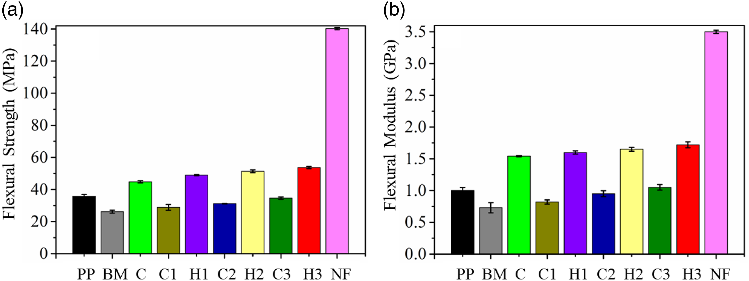
Nonetheless, composites C1, C2, and C3 recorded a very insignificant increase in flexural strength compared to BM. Furthermore, all these composites reported flexural strength lower than that of the pristine PP. This unsubstantial increase of the composites in comparison to BM and PP was due to the flexible nature of NF compared to FA and other reinforcements. Although NF possessed a higher Young’s modulus than PP and BM, the amount of NF reinforced was smaller (2, 4, and 6 wt.%) and was not enough to compensate for the decrease of flexural strength due to the addition of SEBS and SEBS-g-MA into the BM. However, the flexural strength of hybrid composites H1, H2, and H3 was exceptionally large and recorded an increment of ∼37%, ∼43%, and ∼49% compared to PP, respectively. The probable reason behind the superior flexural strength of the hybrid composites is the ceramic nature of FA and good interfacial interaction among all the reinforcements and BM.
Likewise, flexural modulus of the PP, BM, NF, C, C1, C2, C3, H1, H2, and H3 recorded a value of 1, 0.73, 3.5, 1.54, 0.82, 0.95, 1.05, 1.60, 1.65, and 1.72 GPa, respectively. It can be observed that composites C, C3, and all the hybrid composites, H1, H2, and H3, demonstrated flexural modulus superior than pristine PP. NF, a flexible fiber compared to basalt, glass or natural fibers, possessed lesser flexibility resistance when the load was applied under a three-point bending instrument. However, composites C (with 5 wt.% FA) and C3 (6 wt.% NF) showed an increment of 54 and 5%. A stiff and ceramic nature of FA in C and a higher concentration of NF in C3 must have provided stiffness better than the pristine PP. Hence, as a result, all the hybrid composites which contain 5 wt.% of FA in all the composites performed better than pristine PP in terms of flexural modulus. Interestingly, all the composites recorded flexural modulus in between the flexural modulus of PP and NF. The above statement also confirms the reinforcement capability of the recycled nylon fiber into PP matrix.
Impact properties
The notched Izod impact strength of all the samples has been illustrated in Figure 8. It can be observed that PP demonstrated an impact strength of 0.63 kJ/m2. The addition of 10 wt.% of SEBS and 5 wt.% of SEBS-g-MA tends to increase the impact strength of the blend BM to 1.81 kJ/m2. It is believed that crack initiation and propagation were controlled by these micro-rubber particles which were blended with PP which enhanced the impact properties significantly. Furthermore, NF reported an impact strength of 9.11 kJ/mm2 which was highest among all the samples. Hence it was expected that addition of NF will enhance the notched Izod impact strength of all the composites. Notched Izod impact properties of PP, BM, NF and the composites (C1,C2 and C3) and hybrid composites (H1, H2 and H3).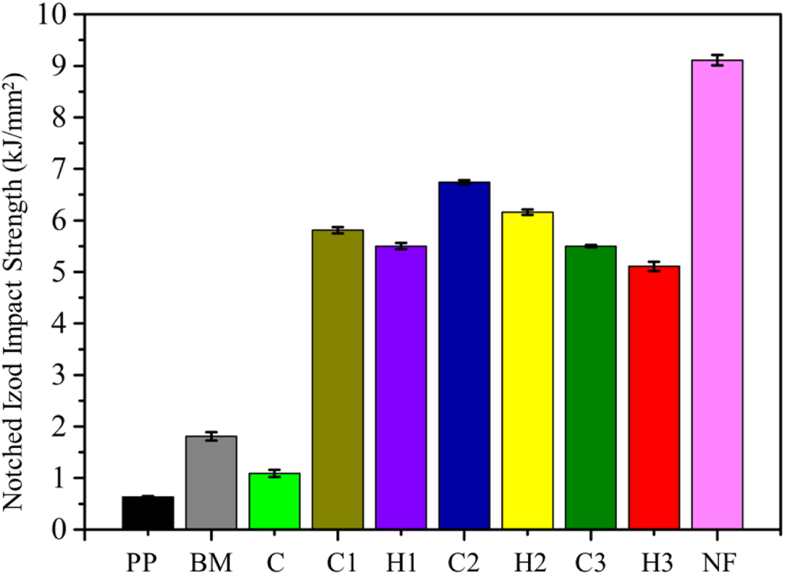
Interestingly, impact strengths of 1.09, 5.81, 6.74, 5.5, 5.5, 6.16, and 5.11 kJ/m2 were possessed by composites C, C1, C2, C3, H1, H2, and H3, respectively. Interestingly, unlike other available rigid brittle fibers, NF offers resistance against sudden load application. It is believed that the impact properties of the natural fiber, basalt fiber, and glass fiber composites decrease due to the fiber fracture. However, NF offers excellent resistance against such sudden forces. Hence, as a result, excellent impact properties of the R-NF reinforced polymer composites have been achieved. Addition of FA to all the composites C1, C2 and C3 resulted into the hybrid composites H1, H2 and H3. Notably, all the hybrid composites demonstrated impact strength lower than that of the corresponding equivalent pristine composite without FA. It was believed that addition of FA decreased the impact strength due to the very high brittle nature of the FA.
Microstructural analysis of the composites
Figures 9(a)–(f) is an illustration of FE-SEM of tensile tested specimens of composites C1, C2, C3, H1, H2, and H3. Among composites (C1, C2, and C3), it can be observed that the NF are well wetted and adhered with the BM, and a very smaller number of fibers appeared to be deboned during tensile testing (Figures 9(a)–(c)). Although some NF were pulled out due to debonding, a large number of fibers participated in sustaining the load transferred from the BM, and hence, fracture of the fibers was prominent demonstrating strong PP-NF interfacial wetting and interactions. The broken tensile samples of hybrid composites H1, H2, and H3 showed better fracture behavior of the NF compared to C1, C2 and C3 (Figures 9(e)–(g)). The apparent increase in good adhesion, wetting and improved fracture of the NF probably happened due to the addition of CTAB treated nano structured FA. It is perceived that nano/microparticles of FA must have contributed to bridging the gap between NF and BM. Additionally, nano structured FA might have contributed to filling the voids and defects during the manufacturing of the samples, and hence, resulted in a strong composite. Microstructure analysis via FE-SEM images of (a) C1, (b) C2, (c) C3, (d) H1, (e) H2, and (f) H3, composites.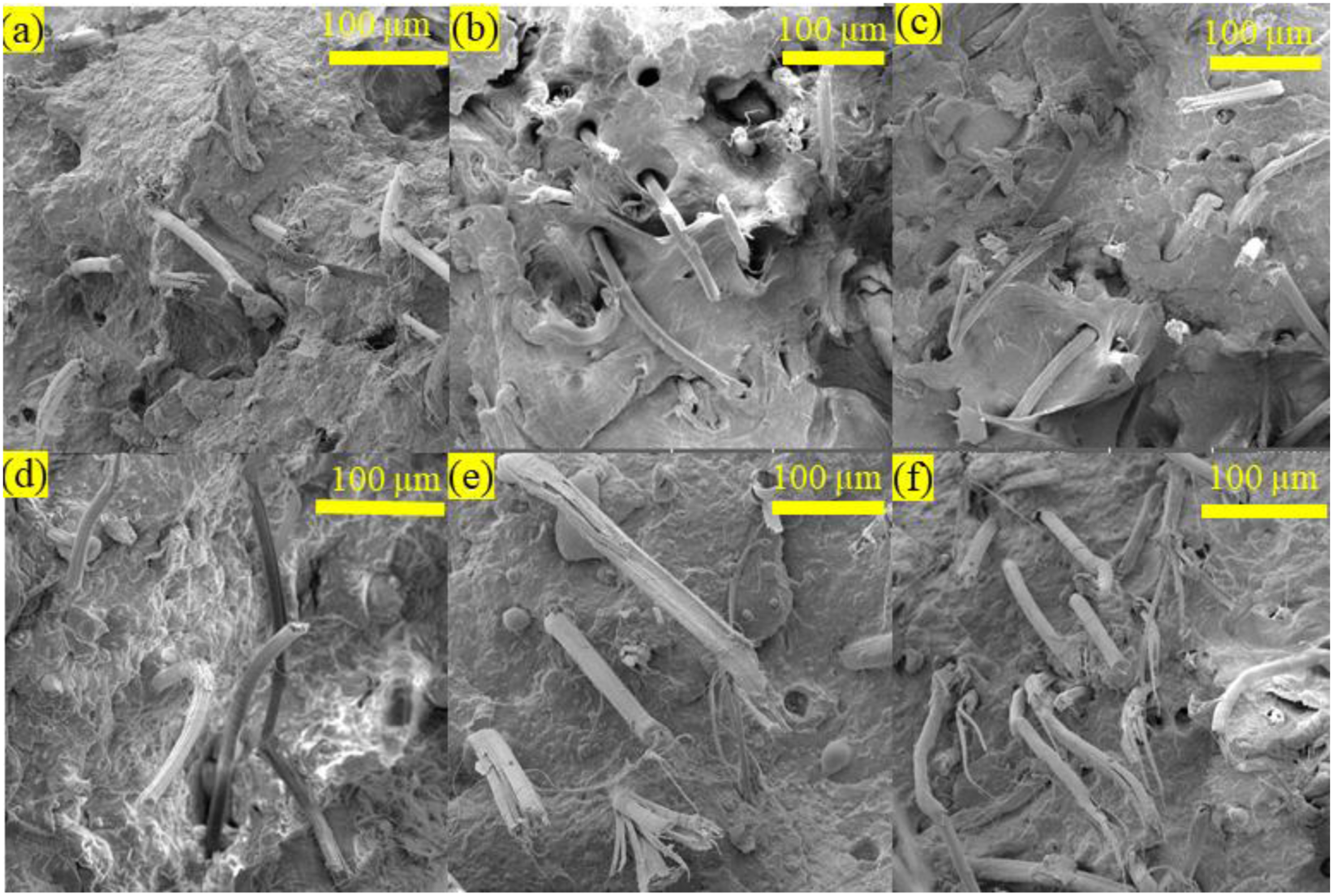
DSC analysis of composites
Melting point, crystallization temperature, and percentage crystallinity
Figure 10 is a thermogram depicting the thermal behavior of the PP, BM, NF and all the composites. The melting point (T
m
), crystallization temperature (T
c
), the heat of enthalpy (∆H), and percentage crystallinity (X
c
) of all the samples were determined using the curve (Figure 10) and Table 2. Furthermore, the maxima (exothermic peaks) and minima (endothermic peaks) troughs present in the curve were used to explain T
c
and T
m
corresponding to the cooling and second heating of the samples. Various phases (α and β) of the isotactic PP have been reported by many researchers, among which the α monoclinic phase is most stable thermodynamically. In the current study, during the second heating of the samples, it can be observed that pristine PP demonstrates a T
m
of 158.40°C, which also confirms that the major component of the isotactic PP contains α phase. This is in good compliance with the data reported earlier by Panaitescu et al for the PP.
60
However, the addition of SEBS and SEBS-g-MA did not affect much the T
m
of the BM (159.78°C). The same insignificant change in melting point of PP/SEBS blend was also reported by many authors61–63. Likewise, pristine NF demonstrated a T
m
of 249.50°C, Which were higher than both PP and all the composites. Thermogram of the heat flow versus temperature of the PP, BM, NF and all the composites. Details of crystallization and melting temperature, melting enthalpy and percentage crystallinity of pristine NF, PP, base matrix and fabricated composites.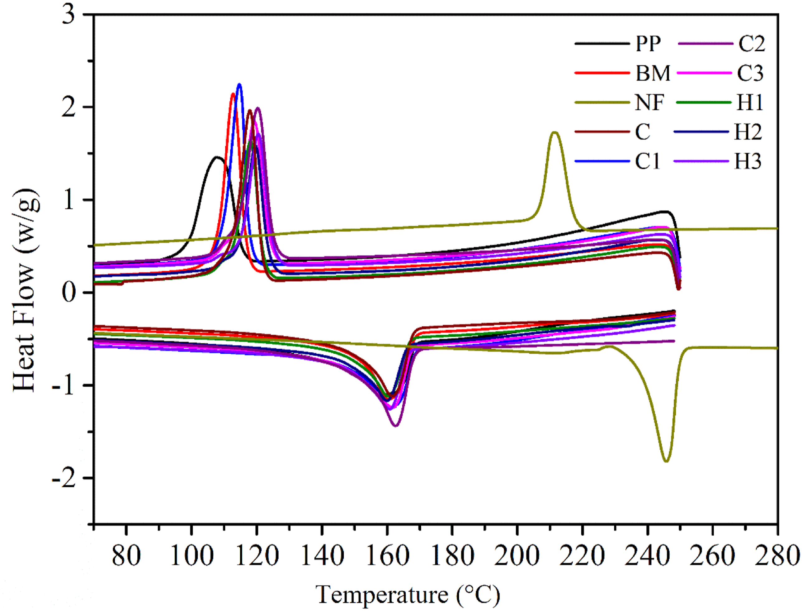
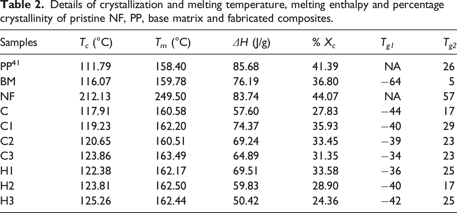
Nonetheless, composites C (161°C), C1 (162°C), C2 (161°C), C3 (163°C) and hybrid composites H1 (162°C), H2 (163°C), and H3 (162°C) exhibited higher melting points compared to that of BM (159.78°C) and PP (158.40°C). Interestingly, all the composites reported T m lower than that of the NF. There was a very insignificant increase in the melting point of the composites due to the addition of reinforcements. A similae extent of increase (maximum ∼3°C) in T m has been reported earlier by Karsli et al, 64 and Ghanbari et al 48 for carbon fiber reinforced PP composites. Likewise, maxima trough from cooling cycle of the composites demonstrates crystallization temperatures of the composites. Crystallization of the composites starts with the nucleation and growth of the polymeric crystals. Interestingly, addition of SEBS and other reinforcements to the composites leads to the heterogeneous nucleation of the composites at higher temperature compared to pristine PP. Hence, as a result BM and all the composites demonstrated improved T c (Table 2). However, T c of the NF was much higher than that of the PP, BM and all the composites and crystal formation starts at a temperature 212.13°C. Also, exothermic peaks of all the composites and blends shown narrower peaks compared to neat PP establishing that heterogeneous nucleation in both BM and composites were predominant compared to spontaneous nucleation in PP. 61 Despite the contribution of reinforcements in nucleation, the pristine PP exhibited higher ∆H and %X c than the composite samples. Probably this apparent decrease in ∆H, and so in %X c was due to the restriction and obstruction provided by the reinforcements to the macromolecular mobility.47,64 Hence, as a result, ordered alignment of the macromolecular chains for developing spherulitic structure of the molecules of the composites might have been disturbed (Table 2). Interestingly, NF shows the highest %X c compared to all the samples which confirms high degree of orientation, crystallinity, and rigid molecular chain.
Glass Transition Temperature
T g of all the samples were reported in Table 2 from the tan δ vs Temperature diagram (Figure S1) recorded from the dynamic mechanical thermal analysis of the samples. PP and NF being pure polymer shows a relaxation peak at 26 41 and 57°C, probably due to the segmental motion of the molecular chains of the polymers. However, addition of SEBS and SEBS-g-MA to the PP into the BM makes overall matrix softer and reflects in the form of decreased T g −64 and 5°C of the BM. 41 The first relaxation peak at around −64°C was due to the presence of soft -ethylene-butylene (EB) block. Likewise, peak at 5°C exhibited due to the hard PP and styrene block. Hence as result, all the composites (C, C1, C2 and C3) and hybrid composites (H1, H2, and H3) demonstrated two T g . Composites C (−44, 17), C1 (−40, 29), C2 (−39, 23), C3 (−34, 23), H1 (−36, 25), H2 (−40, 17) and H3 (−42, 25) depicted T g more than that of the BM confirms, the restrictions towards the molecular chain movement of the BM provided by the reinforcements FA and NF. 65
Thermogravimetric analysis (TGA) of composites
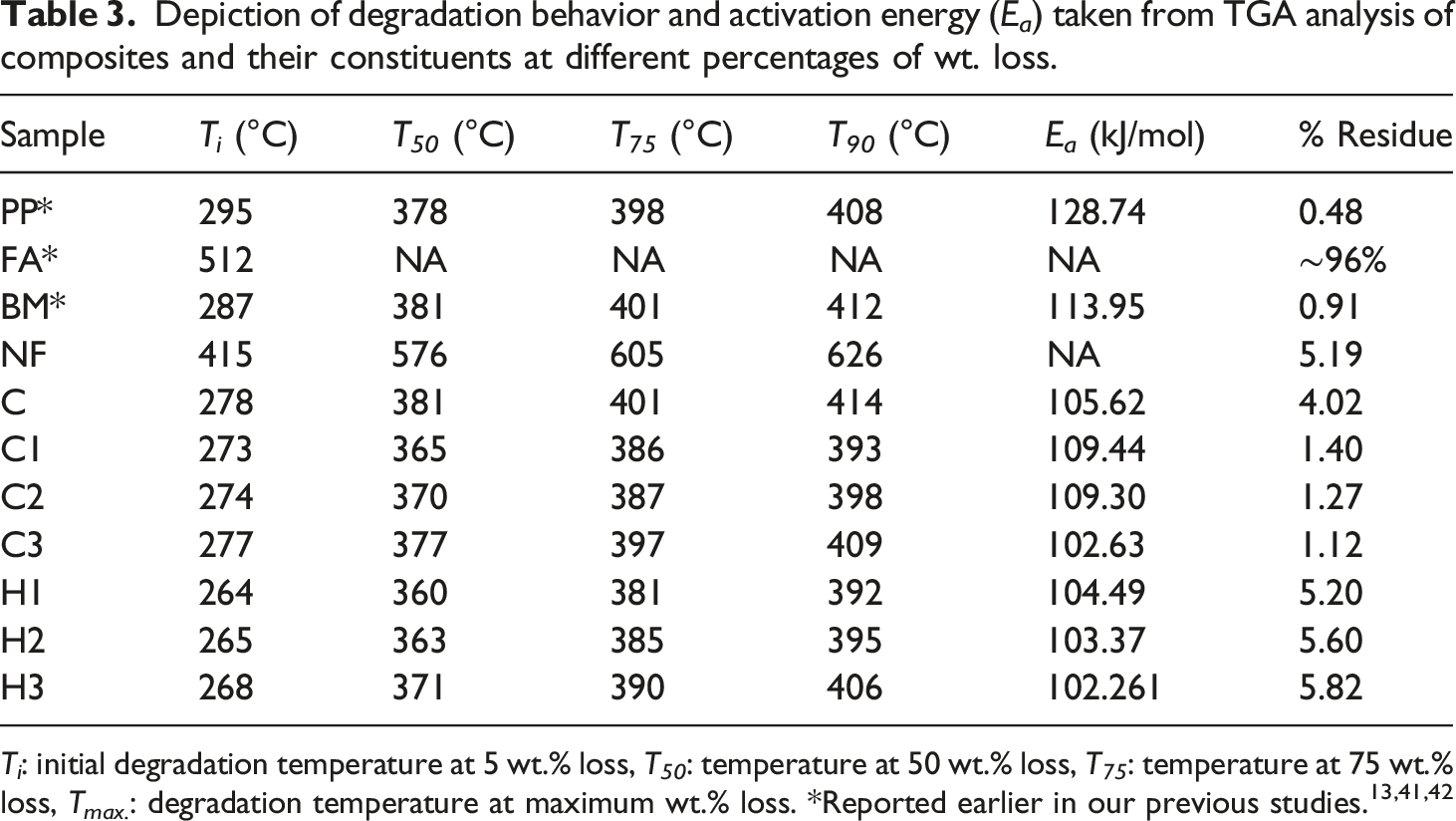
Figure 11 demonstrates the thermal degradation behavior of the PP, BM, and all the composites. Also, Table 3 reports the thermal degradation temperatures, T
i
, T
50
, T
75
and T
90
(°C) corresponding to 5, 50, 75, and 90 wt.% loss along with their activation energies calculated from the Horowitz-Metzger model using equation (2)66,67 explained earlier in section 3.5. The degradation behavior of all the composites was similar to that of PP and BM throughout the entire temperature range (Figure 11). PP and NF reported T
5
at 295 and 415°C. FA being a relatively non degradable burnt material, showed only an initial degradation at T
5
(512°C) due to the presence of wax, carbon, and other volatile impurities. Likewise, all the composites C, C1, C2, C3, H1, H2, and H3 reported T
5
at 278, 273, 274, 277, 264, 265, 268°C, respectively. Furthermore, degradation temperature at T
50
, T
75,
and T
90
did not show much deviation from the thermal degradation behavior of the PP and BM (Table 3). Interestingly, incorporation of reinforcements FA and NF resulted in the alteration of the degree of chain entanglement of the BM and PP. Hence, as a result due to change in pattern of the entanglement, onset temperature of the curves of the composites starts at an earlier stage compared to PP and BM (Table 3). The above result was also in agrrement with the Sengupta et al.
68
This decrease in onset temperature of the hybrid composites (H1, H2 and H3) reduced further due to the presence of 5 wt.% of FA, compared to their only nylon fiber reinforced BM composite equivelents. However, after initial reduction in onset temperature, with the increase of reinforcements (from 2 to 6 wt.%), enhancement in onset temperature was observed for all the composites. This apparent increase might be exhibited due to the degradation phenomena driven by NF and FA at the later stage of the process. Also, NF and FA possessed higher degradation onset temperature compared to PP and BM. The above statement was further reinforced by calculating E
a
values of the PP, BM and all the composites. Initiation and completion of degradation of all the samples were taken at 5 and 90 wt.% loss for the calculation of E
a
(Table 3). It can be observed from the E
a
values that PP followed by BM showed the highest activation energy of degradation compared to all the composites (Table 3). The highest E
a
of the PP is apparently due to a greater number of tie chains, which increases cohesive energy density being translated to E
a
.66,67 However, with the increment of reinforcements, the entanglement of the polymeric chain decreases and results in lower activation energy of the degradation. After the complete degradation of the samples, PP, BM, NF, C, C1, C2, C3, H1, H2 and H3, a residues of 0.48, 0.91, 5.19, 4.02, 1.40, 1.27, 1.12, 5.20, 5.6 and 5.82 wt.%, respectively were left finally. Hybrid composites leave the highest ash content due to the presence of 5 wt.% FA in the samples. Degradation behaviors of PP, BM, NF, FA, and all the composites. Depiction of degradation behavior and activation energy (E
a
) taken from TGA analysis of composites and their constituents at different percentages of wt. loss.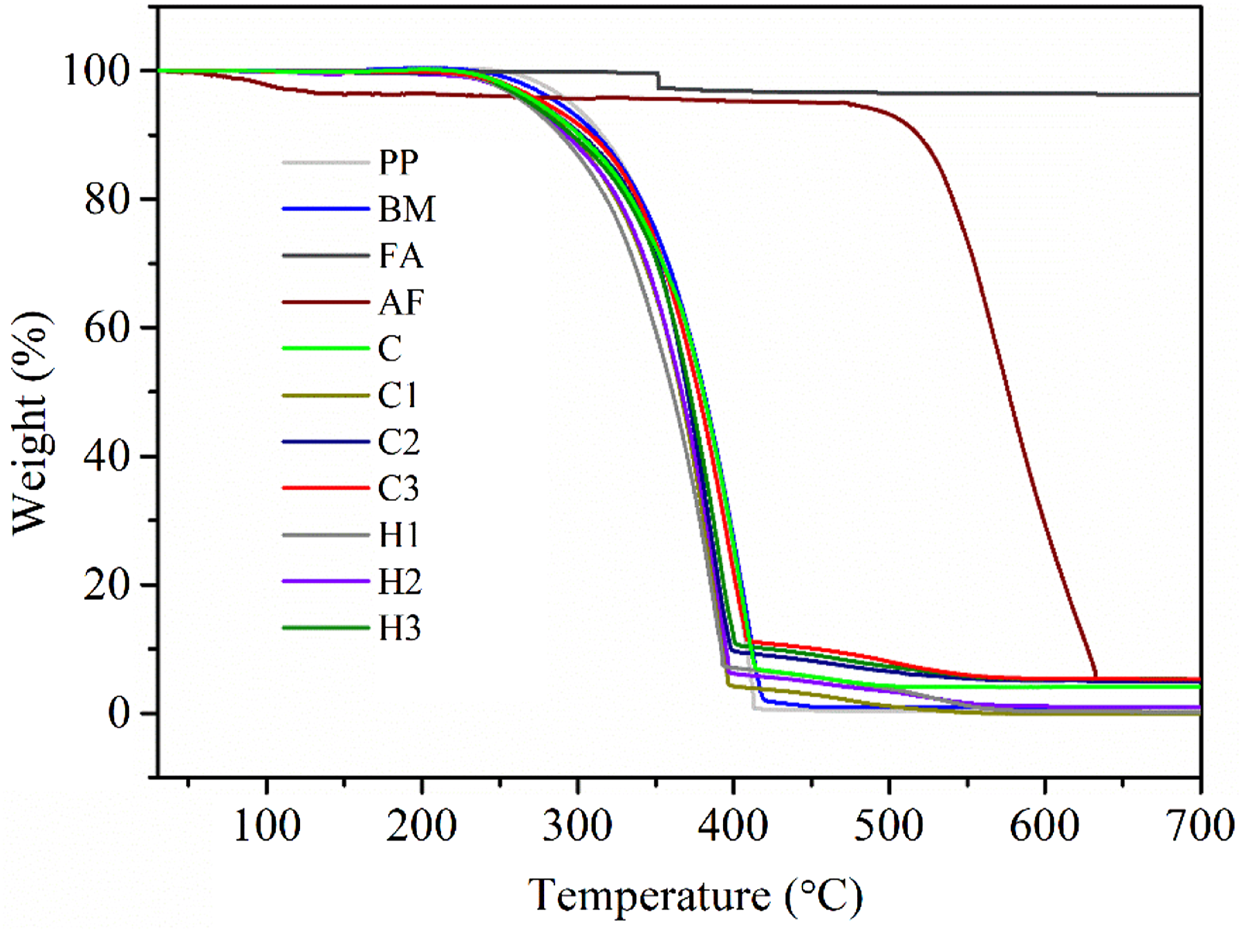
Conclusion
Development of cetrimonium bromide treated nano structured fly ash and recycled nylon fiber reinforced impact modified PP hybrid composites were successfully developed. FTIR and FE-SEM microstructure analysis confirmed the CaCl2, NaOH, and silane treatment of the recycled nylon fiber surface. An increase in the tensile strength (∼29%), tensile modulus (∼3%), flexural strength (∼49%), flexural modulus (72%), and notched Izod impact strength (∼970%) of the hybrid composites confirmed the reinforcement potential of nano-strcutured fly ash and its hybridizing efficiency with recycled nylon fiber when added to PP. Likewise, the morphology from FE-SEM confirmed that nylon fibers in hybrid composites adhered better with the base matrix than the composites consisting of only nylon fiber. Additionally, hybrid composites reported fewer debonding of fibers and greater number of fiber fractures than that in only nylon fiber-reinforced composites. The addition of nylon fiber and fly ash to the base matrix demonstrated a marginal increment in the crystallization temperature of the composites which was confirmed from DSC. Also, a significant change in melting point (∼3°C) and crystallinity (∼41%) of the composites was found in comparison to PP. Thermogravimetry (TGA) reported the highest activation energy of ∼129 kJ/mol for polypropylene.
Supplemental Material
Supplemental Material - Development and characterization of a recycled nylon fiber reinforced and nano-fly ash hybridized high impact performance polypropylene composite for sustainability
Supplemental Material for Development and characterization of a recycled nylon fiber reinforced and nano-fly ash hybridized high impact performance polypropylene composite for sustainability by Atul K Maurya and Gaurav Manik in Journal of Thermoplastic Composite Materials
Footnotes
Acknowledgements
All the authors wish to thank the Indian Institute of Technology, Roorkee for providing excellent research facilities and environment. First author wants to thank the Ministry of Education, Government of India for offering fellowship.
Funding
The author(s) received no financial support for the research, authorship, and/or publication of this article.
Supplemental Material
Supplemental material for this article is available online.
References
Supplementary Material
Please find the following supplemental material available below.
For Open Access articles published under a Creative Commons License, all supplemental material carries the same license as the article it is associated with.
For non-Open Access articles published, all supplemental material carries a non-exclusive license, and permission requests for re-use of supplemental material or any part of supplemental material shall be sent directly to the copyright owner as specified in the copyright notice associated with the article.