
Abstract
Many numerical models of the Automated Fibre Placement (AFP) manufacturing process have been developed to assist in the design process of composite components and structures. Although the tape placement process, in general is a 3-D transient process, limited models considering the 3-D nature of the process exist. This paper describes the development of a 3-D Finite Element (FE) model incorporating the effect of non-concentrated input heat flux distribution on adjacent paths. The model can predict an accurate thermal history of a thermoplastic composite laminate for a complete AFP deposition process. Composite laminates having plies made up of both a single tow and multiple tows have been simulated to study their thermal behaviour during the manufacturing process. Simulations have been conducted both with and without considering the input heat effect on adjacent tows for comparison. Temperatures were measured by embedding two different configurations of optical fibre Bragg grating (FBGs) sensors within the laminate during the lay-up process. This served a dual purpose of validating the model as well as the experimental methodology.
Introduction
The AFP-based composite manufacturing processes are well established for manufacturing both simple and complex composite geometries while providing time and cost savings. It is argued that AFP methods provide tailored design flexibility and exceed the possibilities of other composite manufacturing processes. Using the AFP process for manufacturing thermoplastic composite components is still in development and several comparative studies have found reduced performance in AFP composites as compared to those manufactured using traditional methods such as a hot-press or an autoclave.1–3 Recommendations from previous studies indicate the manufacturing process should be limited to a suitable window of operating conditions during the layup.4,5
For this, many 1-D and 2-D numerical models of the AFP manufacturing process have been developed for estimating the process window by making several assumptions.6–8 Issues related to processability during the manufacture of thermoplastic composites have been discussed extensively by Ghasemi Nejhad et al.9–11 To assist in the design process of realistic composite components and structures, it is required to move from process-level to part-level simulations. 3-D process models are required which can take into account additional 3-D characteristics such as the non-concentrated input heat from a hot gas torch (HGT). Its influence on 3-D parts can be significant as it can affect composite characteristics such as the bonding strength, crystallinity and residual stresses.3,12,13 This paper attempts to elucidate the role of HGT heating on adjacent tows during a layup process and determine its importance for AFP process models. The following subsections provide an overview of the AFP process and the limitations of the current process models based on which the objectives of the work have been defined.
Automated Fibre Placement (AFP) process overview
The AFP machine consists of a robotic arm and placement head, which are controlled using advanced software packages. The layout of the tape placement system in question is shown in Figure 1. During an AFP lay-up, prepreg tows are attached to each other through heat and pressure applied by the placement head. The manufacturing stages consist of the material lay-up, consolidation and curing/melting which are combined simultaneously in the lay-up head, thus improving the efficiency and productivity of this technique. The AFP process uses narrow prepreg tapes which are transported through a creel system to a material placement head which deposits the tows on top of a tool surface or an already existing laminate. During the layup, a hot gas torch heating system applies heat directly at the nip point (the contact point between the incoming prepreg tape and the substrate) and heats the bottom of the incoming tape and the top of the tool or already placed substrate by increasing the temperature to ensure sufficient bonding. The pressure is applied to the substrate by a compaction roller and the tapes are consolidated upon deposition through which any entrapped air gets compressed out of the composite structure.14,15 Schematic layout of the tape placement system (left) and the AFP machine (right).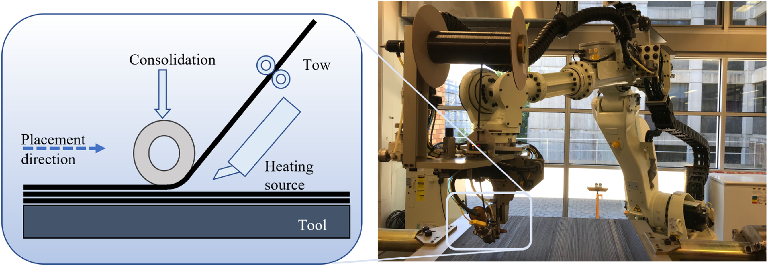
Limitations of the current modelling perspectives
Many numerical models of the AFP manufacturing process have been developed to overcome the trial-and-error approaches for estimating suitable process windows of manufacturing parameters. Most models simplify the problem into one or two dimensions by making assumptions about planar effects. Some of the assumptions include uniform input heat throughout the width of the laminate, low thermal conductivity, and large length as compared to the width or thickness.6,16,17 The tape placement process in general is a 3-D transient process, and moving forward from process-level simulations to part-level simulations requires the 3-D nature of the process to be incorporated into the model.
Not much work has been done to study the influence of heating of the adjacent placement paths during layup on the thermal history during the deposition process. This may be significant when using a hot gas torch for heating as due to the distributed outward flow of the gas from the nozzle, there will also be heat input over an area outside the tow being placed during the deposition process. This may result in a non-uniform temperature distribution in different regions of the component. Even in most previous studies working with 3-D models, single-tow laminates have been simulated wherein the laminate is composed of many single prepreg tapes placed directly on top of each other.18–20 Such models are unable to capture effects such as the influence of non-uniform input heat flux distribution on adjacent paths. Furthermore, most previous studies have simulated the behaviour of small-scaled coupons as compared to the specimen size used for validating the model and the simulation results are then normalized and approximated for comparisons. It may be more appropriate to simulate the behaviour using full-scale simulation models. Since the results from such predictive models are also used as input for other process models, it may affect the conclusions that are made. A detailed 3-D model incorporating the effect of the input heat flux distribution on adjacent paths may be necessary due to the non-uniform nature of hot gas torch heat flux impingement.
Tafreshi et al. proposed a thermal model where the entire composite substrate region was divided into two zones for modelling heat transfer.21,22 However, the input heat from the hot gas torch was assumed to be concentrated in a fixed region and heating of the adjacent zone was not considered. Furthermore, the effect of only a single tow laminate was simulated. A three-dimensional ray-tracing model of the flashlamp heating system in an ATP process was proposed by Danezis et al. 23 The flashlamp heating system heats the substrate through the emission of periodic braodband radiation in the form of high-energy pulses of several milliseconds. Although some of its results may be applicable to other heating systems, the nature of heating is very different to HGT-heating as flashlamp systems offer very controlled heating of the target substrate. Additionally, the effect of compaction from the roller was not considered in the model, the effect of which might also be significant. The effect of a scattered input heat flux over a large substrate simulating the input heat from an IR lamp and the need for proper thermal management for the design of composite components was demonstrated by Lichtinger et al. 24 The study deals with very low peak temperatures of only about 50°C. Furthermore, the influence of the input consolidation pressure from the compaction roller was not considered, although it has been shown previously that the contact conductance can be highly influenced by pressure. 25 Some studies dealing with AFP manufacturing using laser-based heating systems have included heating of an extended zone beyond the width of the prepreg tows. There is usually very minimal heating of the adjacent regions of the substrate when laser-based heating systems are used and this behaviour is modelled by considering an extended heating width slightly larger than the material being placed. In HGT-based heating systems, however, the heat flux from the source is not as well controlled and constrained within a known width on the substrate. Due to this uncontrolled nature, the effect on the substrates adjacent regions may be much more prominent when HGT heating systems are used.26,27 Whether the effect of hot gas torch heat input on adjacent tows for AFP manufacturing of thermoplastic composites is significant or can be ignored in the process models is still unknown.
Objectives and description of the study
The objective of the work was to develop a 3-D Finite Element (FE) model by incorporating the effect of the input heat flux distribution on adjacent towpaths. The model was used for predicting the thermal history of composite laminates for the complete AFP deposition process. Based on this the importance of including hot gas torch heat input on adjacent tows in the models will be determined. Composite laminates having plies made up of both a single tow and multiple tows were simulated to study their thermo-mechanics behaviour during the AFP manufacturing process. Simulations have been conducted both with and without considering the input heat effect on adjacent tows for comparison. For validating the model, an experimental study was also conducted for measuring the thermal history in terms of the peak temperatures attained by the different individual tows during the entire deposition process of both single and multi-tow laminates. Temperatures were measured by embedding different configurations of optical fibre Bragg grating (FBGs) sensors within the laminate during the lay-up process. For validating this methodology, temperatures obtained from two different configurations of FBG sensors have been compared for the first time.
Experimentation
Material
AS4/PEEK thermoplastic prepregs tows having a fibre volume fraction of 60% and dimensions of 80 mm along the length, 12.7 mm across the width and 0.15 mm through thickness were used for manufacturing the composite material specimens. 28
AFP placement trials
Composite laminates consisting of single-tow plies and multi-tow plies were manufactured employing the Automated Dynamics AFP machine to lay the tows in a unidirectional manner. 10 tows were stacked on top of each other for the single-tow laminate and a total of nine tows arranged into three plies of three tows each were used for the multi-tow laminate, as shown in Figure 2. The layup was done using the following set of processing parameters: a) Material deposition speed = 76 mm/s, b) HGT temperature = 950 °C, and c) Consolidation force = 180 N. These parameters were based on an experimental study conducted to obtain a processing window for optimising physical and mechanical properties.
14
Standard apodized polyimide-coated FBG sensors were used for the in-situ measurement of temperatures. The sensors had a grating length of 10 mm and a cladding diameter of 0.125 nm. Sensors having variable peak reflected wavelengths between 1530 nm to 1550 nm were used. The sensors were glued to the substrate using a methyl 2-cyanoacrylate-based common glue. The layup was done directly on top of the sensors for it to record the changes in wavelength as a result of external stimuli from the layup. Pictorial representation of a sensor embedded in single and multi-tow laminates as viewed from the end (All dimensions in mm).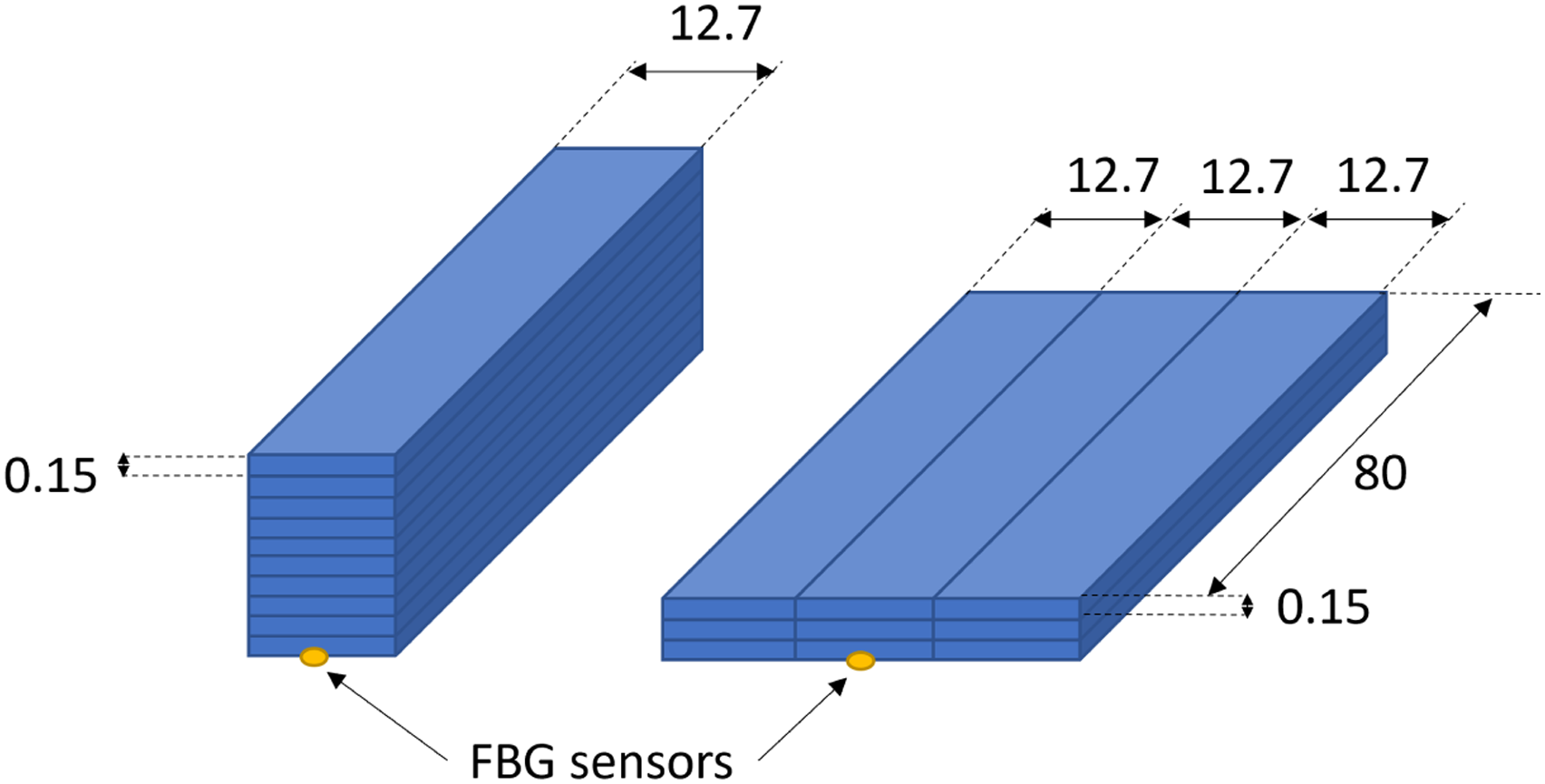
For extracting the contribution of heat to the recorded change in wavelength, two identical sensors were placed at different orientations in the same region within a ply. The first sensor was placed in alignment with the fibres in the unidirectional ply, while the second sensor was placed at an angle to it, as shown in Figure 3. This was done to ensure that the angled and straight sensors have different strain sensitivities (κ
ɛ
) due to their relative orientation. The thermal sensitivity (κ
T
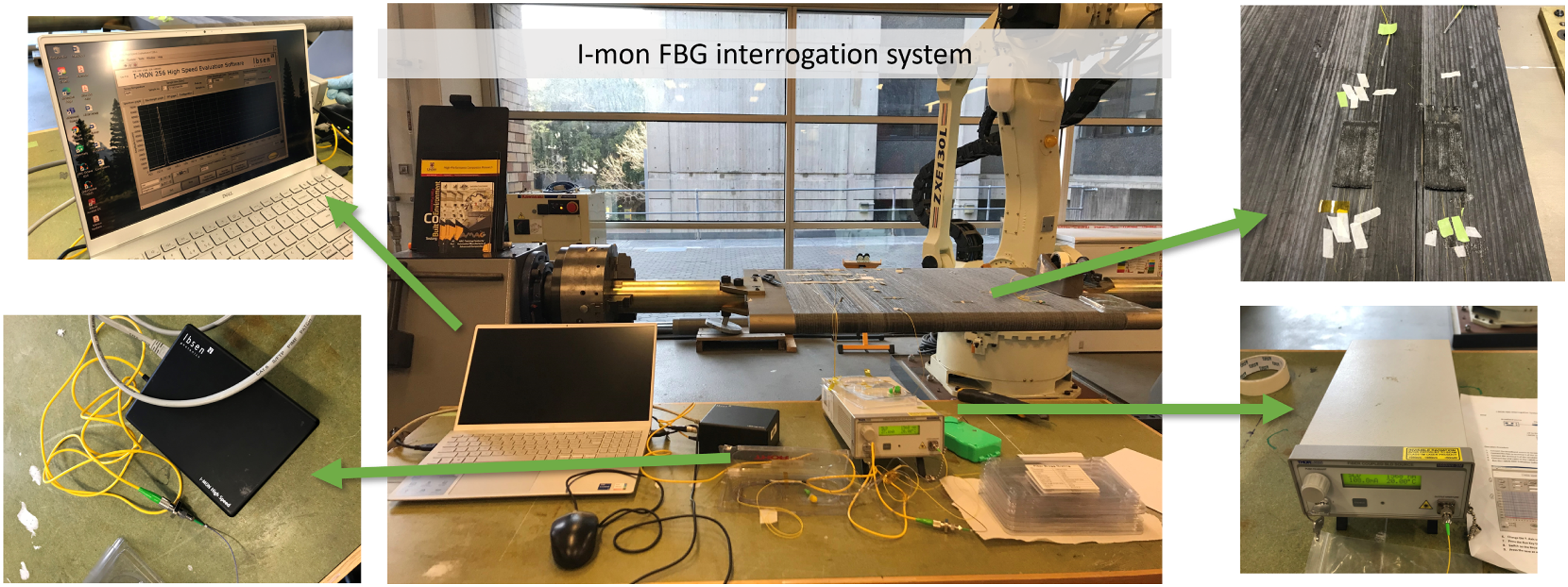
) of both the sensors however remains the same as it is relatively unaffected by the orientation of the sensor to the composite laminate. The temperature and strain in the vicinity of the FBG sensors can be estimated using the characterisation matrix given by equations (1) and (2).29,30 The experimental and data acquisition setup is shown in Figure 4. Relative orientation between a straight and angled FBG sensor. The experimental and data acquisition setup. Broadband source (bottom right), I-MON FBG interrogation system (bottom left), connection to computer (top left), specimens with embedded FBG sensors (top right).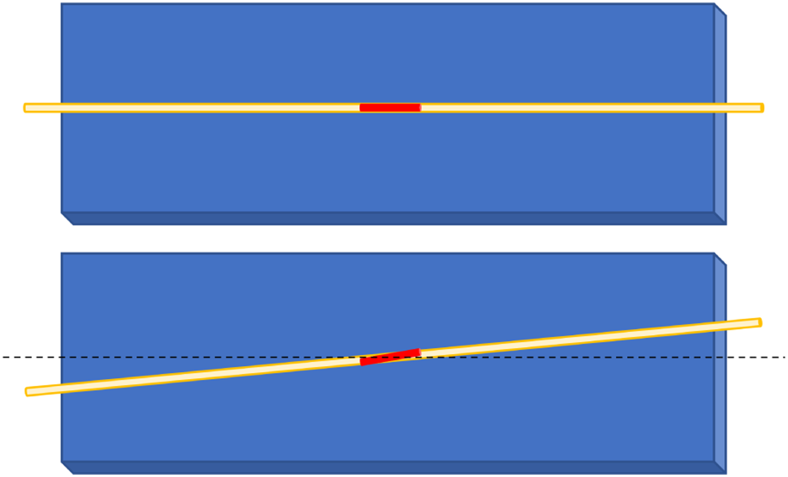


Although this methodology has been used previously by a few studies,30–33 to test the reliability of the methodology of using angled sensor configuration for estimating in-situ temperatures in a composite laminate during manufacturing, two different sensor configurations were used. The angled sensor was placed at an angle of 5° relative to the straight sensor in the first case, and at a relative angle of 15° in the second case. Such a validation exercise of using multiple combinations of the angled FBG sensor configurations has been used for the first time for testing the methodology. For the multi-tow laminate, only one sensor configuration was used, and the angled sensor was placed at an angle of 15° to the straight sensor.
For calculating the temperatures using equations (1) and (2), the individual strain and thermal sensitivities of all the three sensors were measured, i.e. the ones aligned at 0°, 5°, and 15°. The thermal sensitivity of all the three sensors under normal conditions depends primarily on the thermal expansion coefficient of the fibre and is independent of the sensing head geometry, and is 10 p.m./°C.
29
The strain sensitivity of each of these differently aligned sensors is different and was calculated experimentally. After conducting the manufacturing trials to prepare the specimens, the manufactured specimens with the embedded FBG sensors were tested using a tensile test machine (Instron 3369). A longitudinal extensometer was installed on the centre of the specimen and the ends of the embedded FBGs were connected to the interrogator system, as shown in Figure 5. The tensile testing machine was loaded under the strain control method and the sample was subjected to an incrementally increasing strain up to 750 μɛ at the constant rate of 0.5 mm/min. The reflected wavelength from the FBG sensor was measured using a commercial FBG interrogator system (IMON-256, Ibsen Photonics) regularly. The strain sensitivity of the sensor was obtained from the slope of the obtained experimental curves between the change in wavelength and the corresponding strain. The calculated strain sensitivity for the three sensors were 0.10, 1.16 and 1.90 p.m./μɛ, respectively. Tensile testing setup used for measuring the strain sensitivity of the sensors embedded inside a composite material. A longitudinal extensometer was installed on the centre of the specimen (left) and the ends of the embedded FBGs were connected to the interrogator system (right).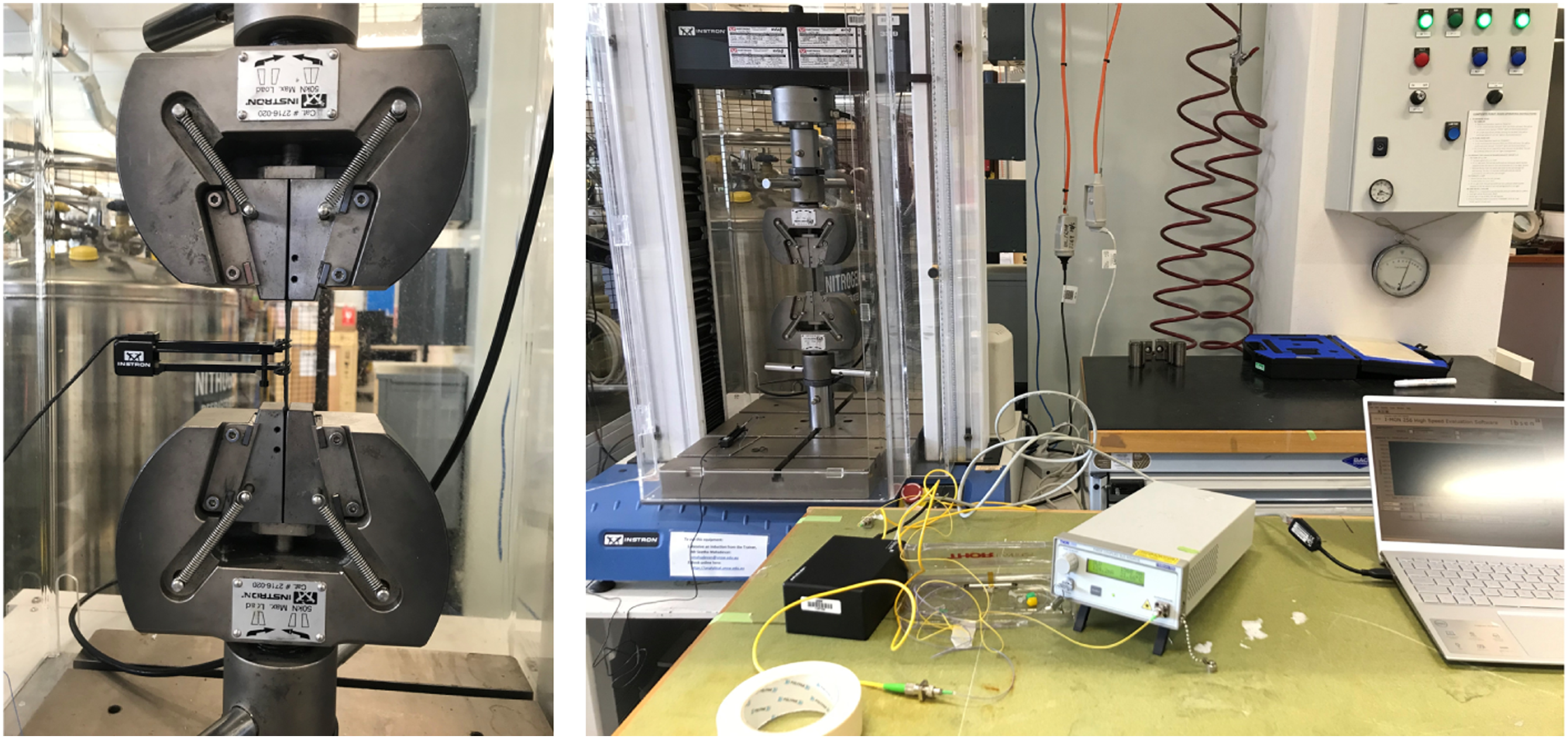
Modelling approach
A 3-D FE model was developed to study the interactions between the thermal and mechanical properties of the HGT based AFP composite manufacturing process. The model was simulated with an Abaqus/Explicit solver using a coupled temperature-displacement analysis. The heat flux was applied directly in front of the nip point. Consolidation pressure was applied to simulate the effect of the consolidation roller. The effect of multiple adjacent tows within a ply was considered in the model. Additionally, both uniform and non-uniform heating across the width have been considered.
Part and laminate modelling
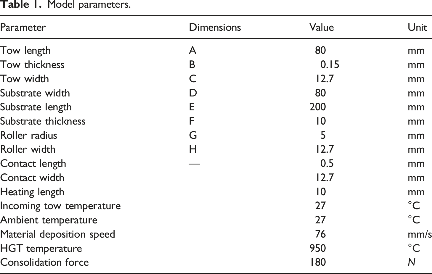
Model parameters.
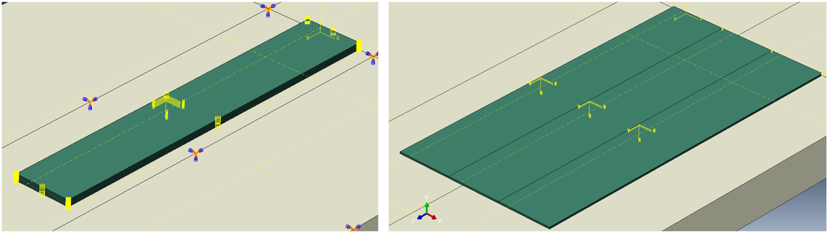
Single-tow (left) and multi-tow (right) model with ply parts stacked on top of each other and in the adjacent region to form a laminate assembly.
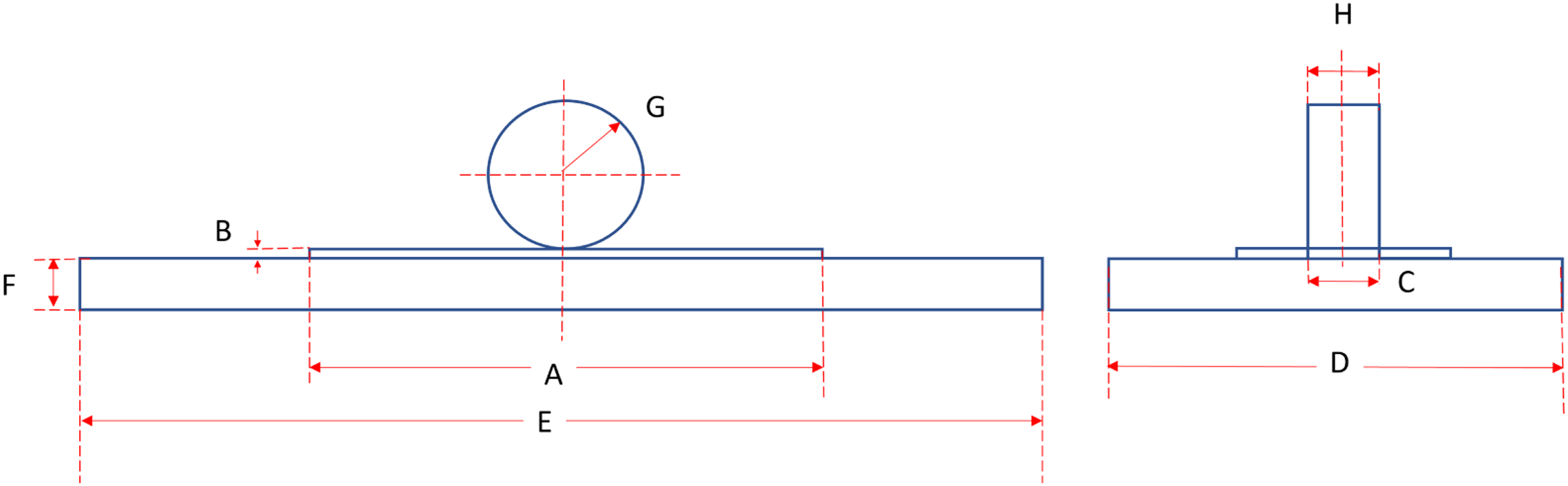
Model geometry. Refer to Table 1 for dimensions (Figure not to scale for clarity).
Application of heat flux and pressure load
For simulating the tape placement process, the tows were placed on top of previously laid substrates followed by the application of heat and pressure moving from one end to the other. The transient loads, i.e. the input heat flux and the pressure load have been implemented in the model using Abaqus ‘user-subroutines’ DFLUX and DLOAD, respectively.
The contact pressure and contact area were estimated by conducting a finite element contact study between the roller and the thermoplastic prepreg tape. In the analysis, a prepreg tow was laid on top of a substrate followed by the application of an input force of 180 N through a consolidation roller. The corresponding deformation in the material was used for estimating the contact length (0.5 mm). The contact width was the same as the width of the roller. The shape and magnitude of the simulated contact stress profile were obtained from the contact model and the same was approximated as input for the AFP process models. The obtained contact stresses and width were also compared with the analytical Hertz solution. More details about this method and the corresponding equations can be found in Oromiehie et al. 31 The heating length was approximated as 10 mm, based on the distance between the nip point and the nozzle of the HGT.21,22 The characteristics such as the speed of material deposition (76 mm/s), heating length (10 mm), contact length (0.5 mm) and width (12.7 mm), were specified in the subroutine.
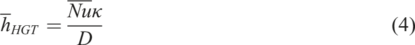
The input heat in the AFP process model was applied as an external boundary condition to model the applied heat flux (q”) which for a hot gas torch can be approximated by equation (3), where, 
Heat transfer model
Due to the differences in temperatures, large thermal gradients can develop, and heat is conducted through the material and also dissipates to the surroundings, which was specified via conduction and convection mechanisms. The generalised heat transfer equation in orthotropic materials can be described by equation (5) in Cartesian coordinates. Where ρ, C
p
, T, U and t are the density, specific heat, temperature at a material point, heat generation coefficient, and time, respectively. The terms K
x
, K
y
and K
z
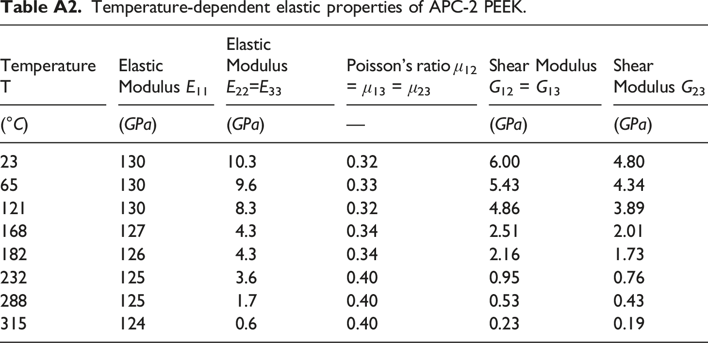
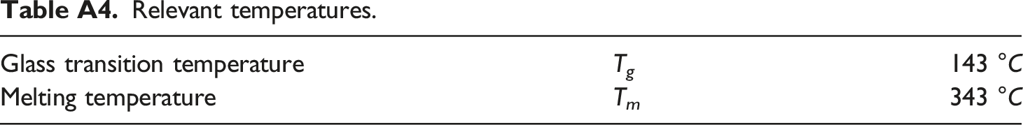
are the thermal conductivities of the composite in x, y, and z coordinates. The tool temperature was defined to be 60°C for the study but can also be varied as per requirement. The initial tow temperature was defined to be the same as the ambient temperature which was fixed at 25°C. The temperature-dependent material properties of the CF/PEEK (APC-2 PEEK) composite material in terms of its conductivity, density, elastic behaviour, thermal expansion coefficient, and specific heat are given in Appendix A in Table A1, Table A2, Table A3 and Table A4.6,7,19,31 These properties allow the model to predict the changes in material behaviour because of abrupt changes in temperatures.
After consolidation, the top surface of the substrate begins to lose heat via convection resulting in a drop in the temperature of the substrate. Convection loads were specified for all surfaces exposed to the environment and were deactivated after the placement of a subsequent tow on top. A convective heat transfer coefficient of 10 W/(m2)°C was used.
Modelling the contact surfaces
All the surfaces in the different tows of the laminate which are in contact with each other were assigned mechanical and thermal interaction properties, i.e. the top, bottom, the left and right side of each tow. Heat loss from the front and back of the tow was ignored, due to its small surface area and absence of direct contact with any part. For the mechanical contact, a non-linear contact stiffness with the ‘hard’ contact type was assigned with cohesive properties for CF/PEEK material
38
along with a ‘penalty’ stiffness approximation to resolve potential contact issues. The penalty method approximates hard pressure-overclosure behaviour. The penalty method can mitigate overconstrain issues and reduce the number of iterations required in analysis and improves solver efficiency.
39
Similarly, the ‘GAPCON’ thermal approximation method was used to model the thermal contact properties of the interface. This method can be used in ABAQUS to overcome potential convergence issues arising due to insufficient contact. The thermal contact can be treated as either contact between two interfaces touching each other (perfect contact) or interfaces with a gap between them. The heat transfer between interfaces in ABAQUS is defined as in equation (6). Here, Q is the heat transfer between two corresponding nodes, h is the coefficient of gap conductance, and T1 and T2 are the temperatures of the two surfaces.
40
A GAPCON value of 1500 JT−1L−2θ−1 was used with a clearance of 0.1 mm. An optimisation study for estimating the effect of clearance-dependent conductivity is also available in literature.
19
The front end of each tow was constrained within its plane by applying an in-plane constraint boundary condition.
Multi-tow model with heating of the adjacent region
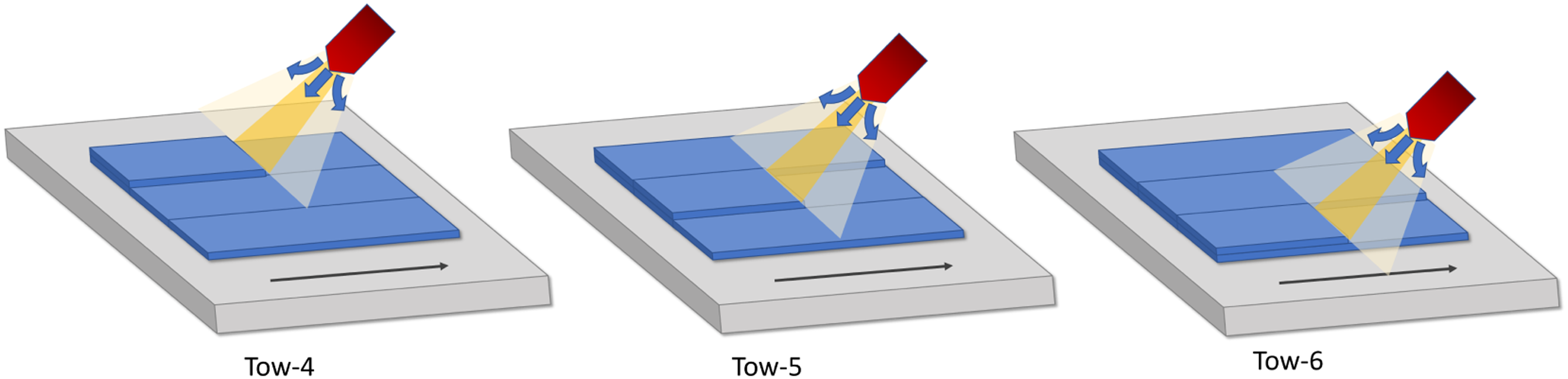
During an actual composite layup, if there are additional tows already laid on the substrate in the adjacent regions, they may also experience some heating especially when a hot gas torch heating source is used as the input heat from the torch travels in all directions after leaving the heat source. The heat flux from a hot gas torch may not be concentrated only in the region of the new tow being added but flows outwards and spreads across in all directions. As a result the previously laid tows in the adjacent region also get heated, albeit at a reduced intensity. To take this into account several modifications were made to the multi-tow laminate model. The different surfaces to be heated during the placement of a particular tow were identified and the exact coordinates of the adjacent tow were defined in the user-subroutine DFLUX. The entire substrate region was divided into two zones, the central zone and the adjacent zone for each placement step. The central zone covers the width of the tow (=12.7 mm) being laid at any moment, while the adjacent zone covers a tow width (=12.7 mm) on each of the adjacent sides, as shown in Figure 8 (right). The length of the heating zone was 10 mm, as in the previous case. The impinging heat flux would ideally be circular in shape but has been approximated by a moving rectangular-shaped flux. Heat flux with the maximum intensity was applied in the central zone while a reduced heat flux equivalent to a heat transfer coefficient of 329 W/(m2K) was applied on the adjacent zone, i.e. on either side of the new tow being placed on the substrate. As in the previous case, this value was calibrated to match the temperature measured experimentally. Depending upon where on the substrate the new tow is being added, the definition of the adjacent region was modified. The adjacent region where the reduced heat intensity is applied could either be on the substrate itself or on the tool on which the layup is being done as demonstrated in Figure 9 for the placement of three different tows (Tows four, five and six) as an example. Schematic showing the comparison between heat flux application: a) without considering heat input on adjacent tows b) considering heat input on adjacent tows. Different scenarios for the moving central and adjacent region during tow placement demonstrated for three different tows during their placement.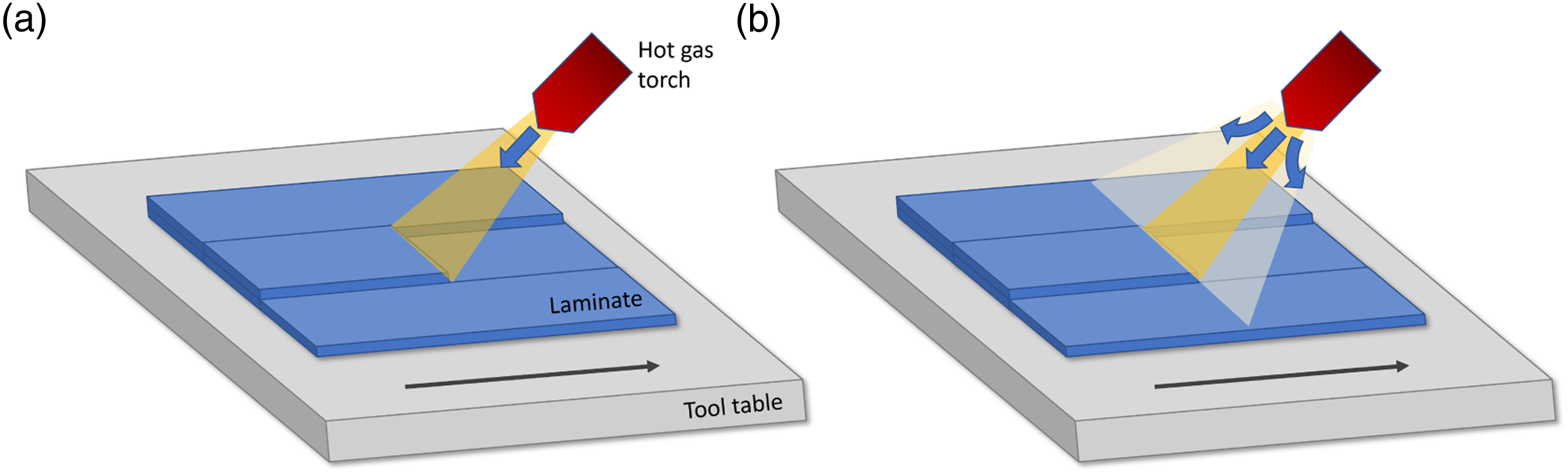
Results and discussions
Experimental results
Temperatures measured using the two combinations of FBG sensors are shown in Figure 10. The temperature at the bottom of the second ply (or the interface of the first two plies) was measured. The peak temperature upon the addition of subsequent layers on top is depicted. For each ply, the rise in temperature upon addition of new plies on top keeps on decreasing. This is because the presence of additional layers in between provides an increased insulation effect limiting the amount of input heat that reaches the bottom ply. For both cases, the experimental temperature for the first tow is missing. This is because when the ply layup is done directly on top of the FBG sensors, the sensors are disturbed and are subjected to large dislocations from their original position which affects the measurement as the FBG sensors are very sensitive to external stimuli. Once the first ply is laid on top of the FBG sensor, the sensor is completely secured from all sides and provides accurate measurements for the placement of subsequent prepreg tows on top of it. Comparison of the peak temperatures observed during the placement of different tows in the single-tow laminate between the FBG experiments conducted using the two different angled sensor configurations (5° and 15°).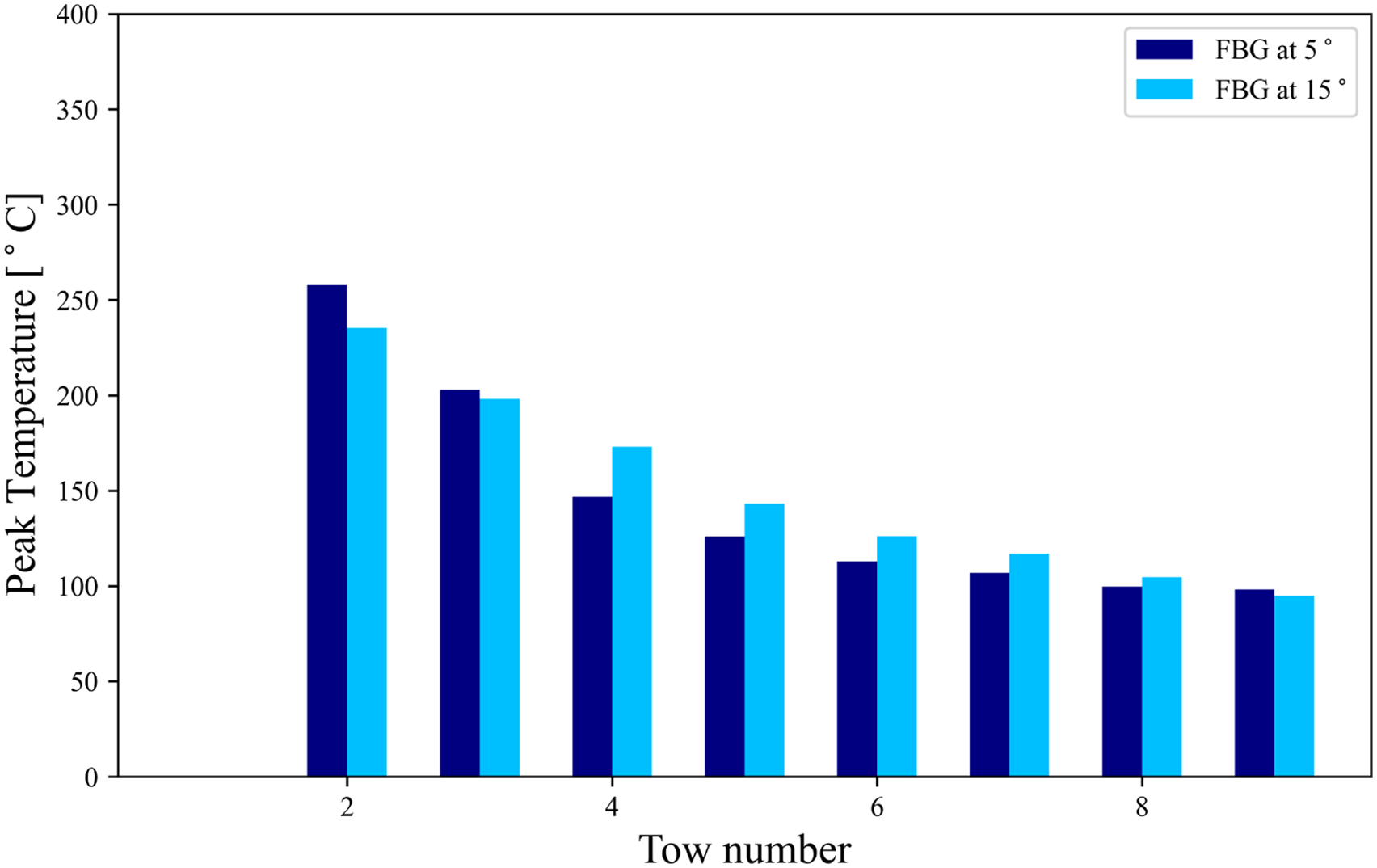
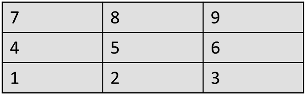
Similarly, for the multi-tow laminate, the experimental results for the temperature at the bottom of the second ply (or the interface of the first two plies) were chosen and the sensor was placed at the bottom of the middle tow. The results are shown in Figure 11. The layout of the different tows in the multi-tow laminate is depicted in the schematic shown in Figure 12. Peak temperatures measured during the FBG experiments conducted for the multi-tow laminate. Schematic depicting the layout of the different tows in the multi-tow laminate.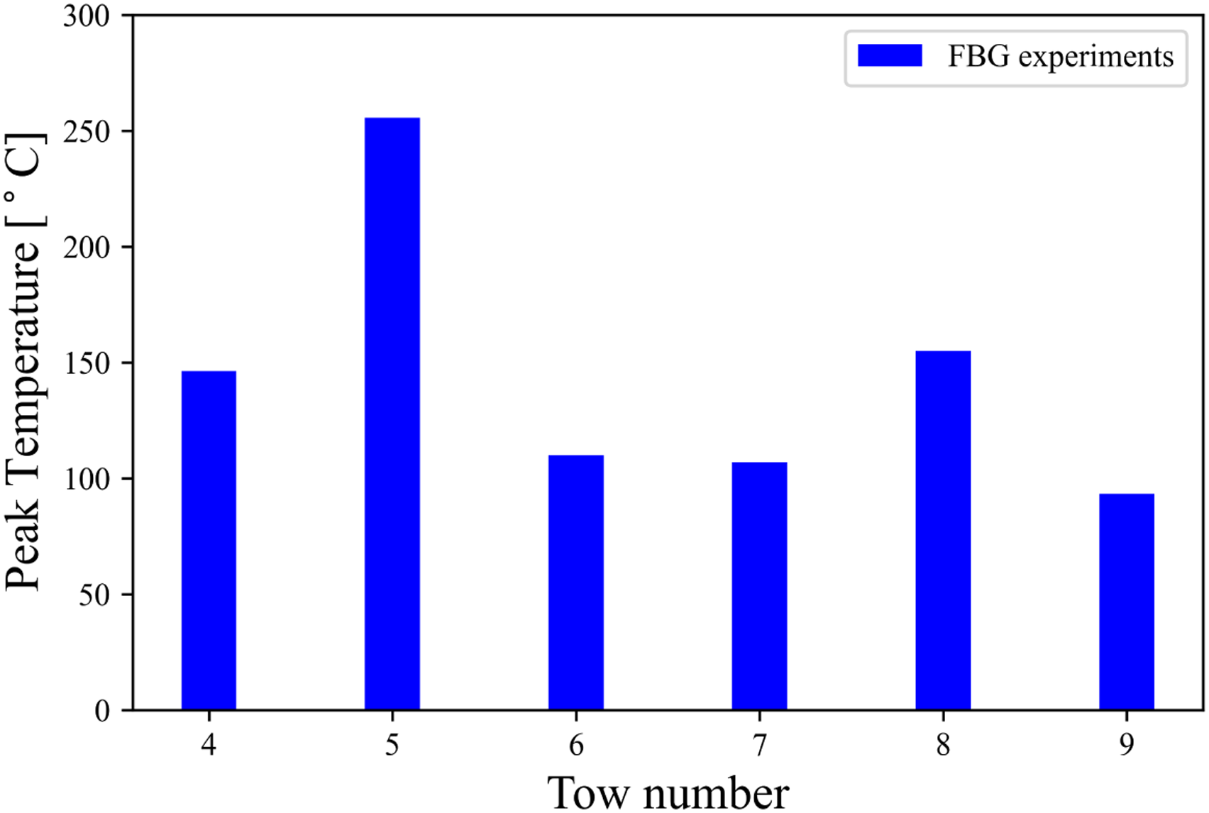
Mesh sensitivity for the model
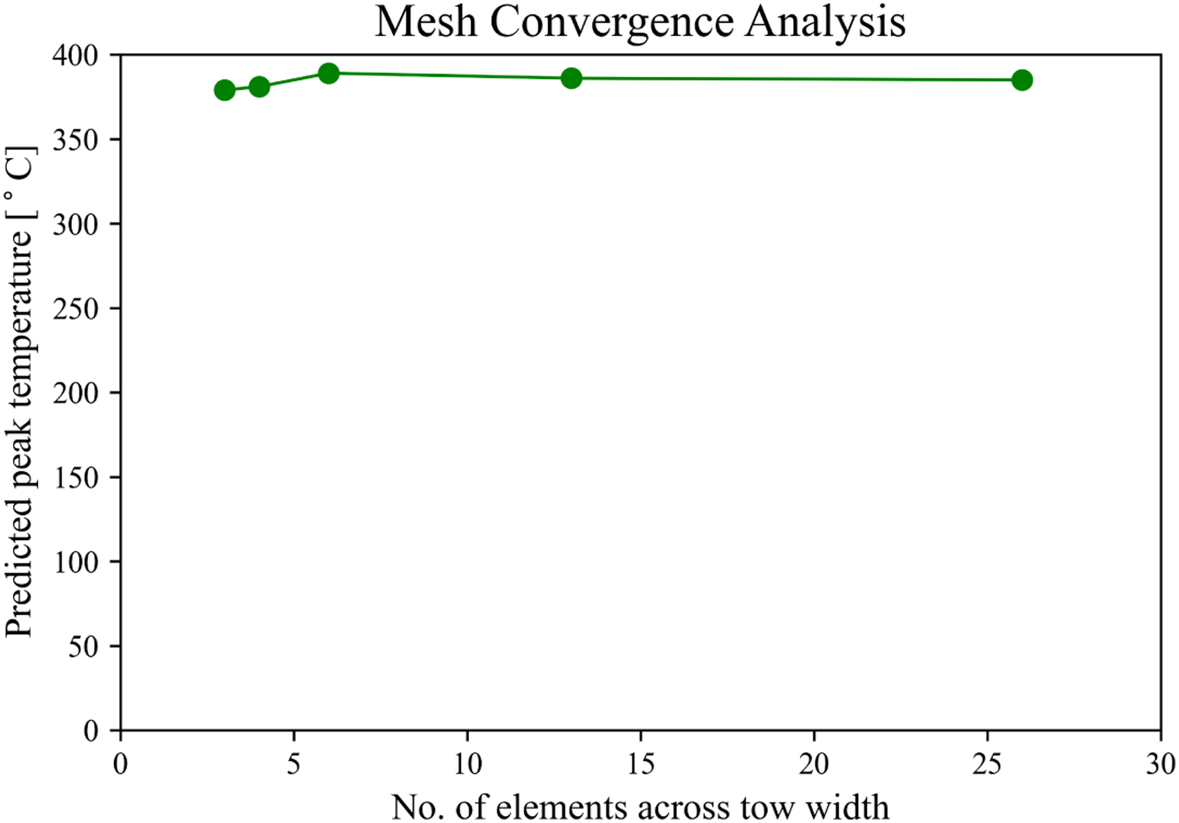
A mesh sensitivity study was conducted to determine a suitable mesh size for the tow parts. The mesh sensitivity analysis can be performed by monitoring any parameter in the system such as temperature, strains, energy, etc. Since the most important parameter for the present study is temperature, it was selected for the analysis. The maximum temperature reached in the prepreg tows due to the applied heat flux was compared for different mesh densities. The prepreg tows were meshed with coarse, medium and fine elements. The number of elements across the width of each tow was varied at six different levels of 26, 13, 6, 4, and three elements for different simulations, imparting a fine, medium or coarse mesh nature to the modelled tows with element sizes varying between 0.48 mm to 4.2 mm. Figure 13 depicts the mesh densities for the extreme cases of three (left) and 26 elements (right) across the tow width, along with an intermediate case of six elements across the tow width (centre). It can be seen from Figure 14 that by decreasing the number of elements across the width from 26 to six and thereby modifying the mesh size from fine to medium, the estimated temperature remains fairly consistent. On further decreasing the number of elements across the width from six to three and thereby modifying the mesh size from medium to course, the estimated temperature starts deviating. Based on the mesh sensitivity study the remaining simulation studies were conducted by using six elements across the width of each tow for the entire laminate assembly.41,42 Depiction of mesh densities for the extreme cases of three and 26 elements across the tow width (left and right), along with an intermediate case of six elements across the tow width (centre). Effect of mesh size (number of elements across the width) on the predicted peak temperature.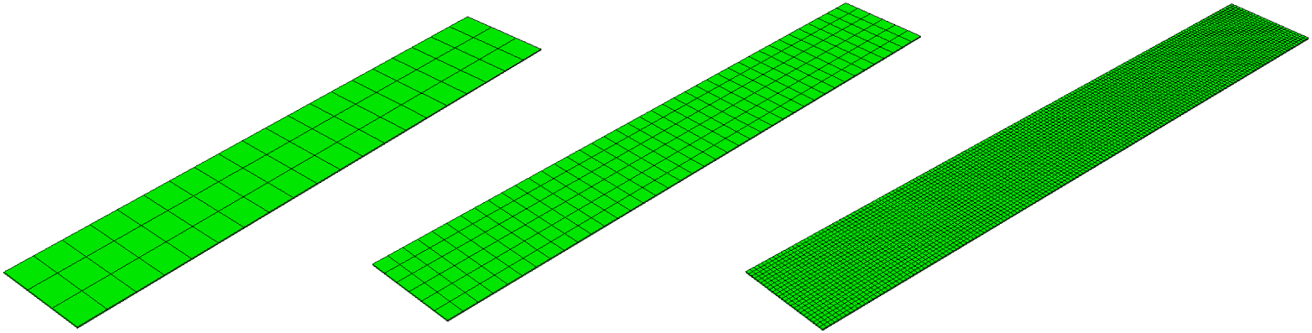
Model predictions
Using the numerical model developed, the temperature distribution of the different types of laminates was determined. The thermal history of all 10 plies for the simulated single tow laminate is shown in Figure 15 which were generated from the default set of model parameters. Each curve originates at the time of its placement and continues until the end of the overall process, i.e. until after the 10th tow has been laid down to form the laminate. For each step, the placement of the tow takes about 5 s, including the tool return time, and causes a rise and fall in temperature in all the previously laid tows beneath it. The total time depends on the specified material deposition speed which also corresponds to the speed at which the input heat flux and the applied consolidation pressure move in the process model. Simulated thermal history of all 10 tows for the single-tow laminate.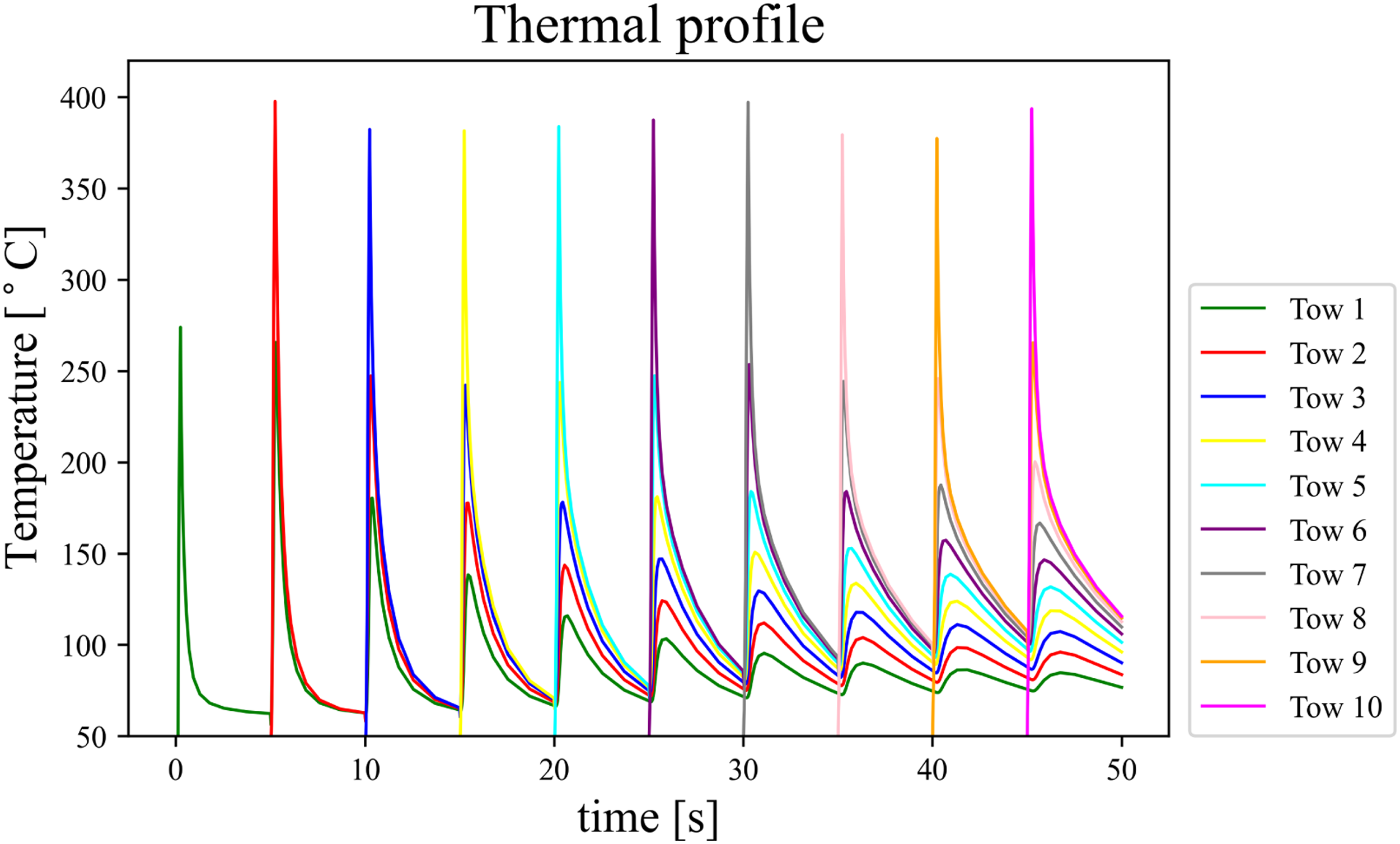
The entire manufacturing process for the ten-ply laminate takes 50 s to complete, the corresponding behaviour for which the model tries to capture. Each tow, except the first one, is found to reach a peak temperature of about 398°C, and can be seen to follow a similar thermal history as the corresponding tows placed thereafter, with a maximum variation of
Similarly, for the case of the simulated multi-tow laminate, the thermal history of all the tows in the laminate is shown in Figure 16. Again, the peak temperature in the tows forming the first ply (Tows 1, 2, and 3) is lower as compared to the rest of the laminate because of a higher conductive heat loss due to the direct contact with the metallic tool. The peak temperature in the rest of the plies is therefore observed to be comparatively higher and reaches up to 395°C. Simulated thermal history of all tows for the multi-tow laminate.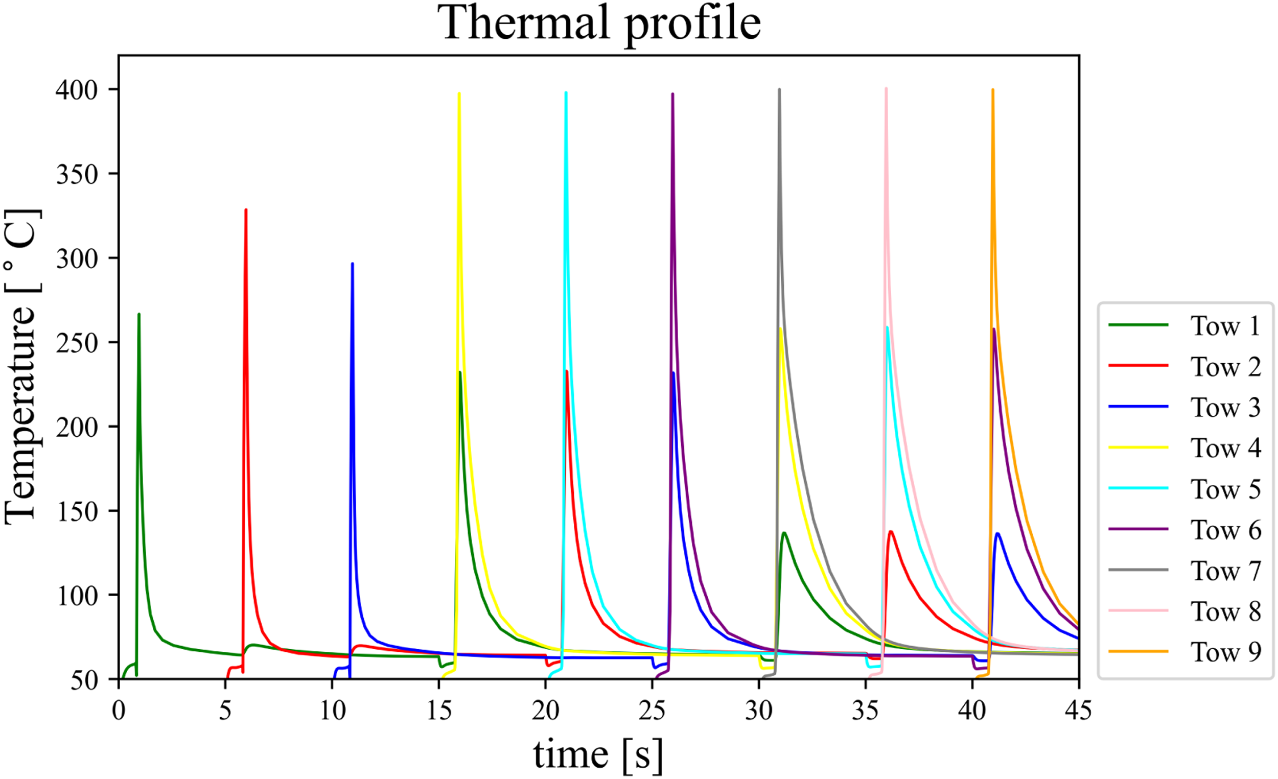
For the multi-tow laminate in which heating on the adjacent tows was considered, the predicted temperature profile is shown in Figure 17. The variation in temperature starting from the placement of the fourth tow until the end of the process is presented. The drop and rise of temperature are due to the location of the point of interest being at the middle of the bottom ply. Simulated thermal history for the middle tow of the multi-tow laminate on considering the effect of adjacent tow heating. Temperatures from the placement of Ply-4 onwards are displayed.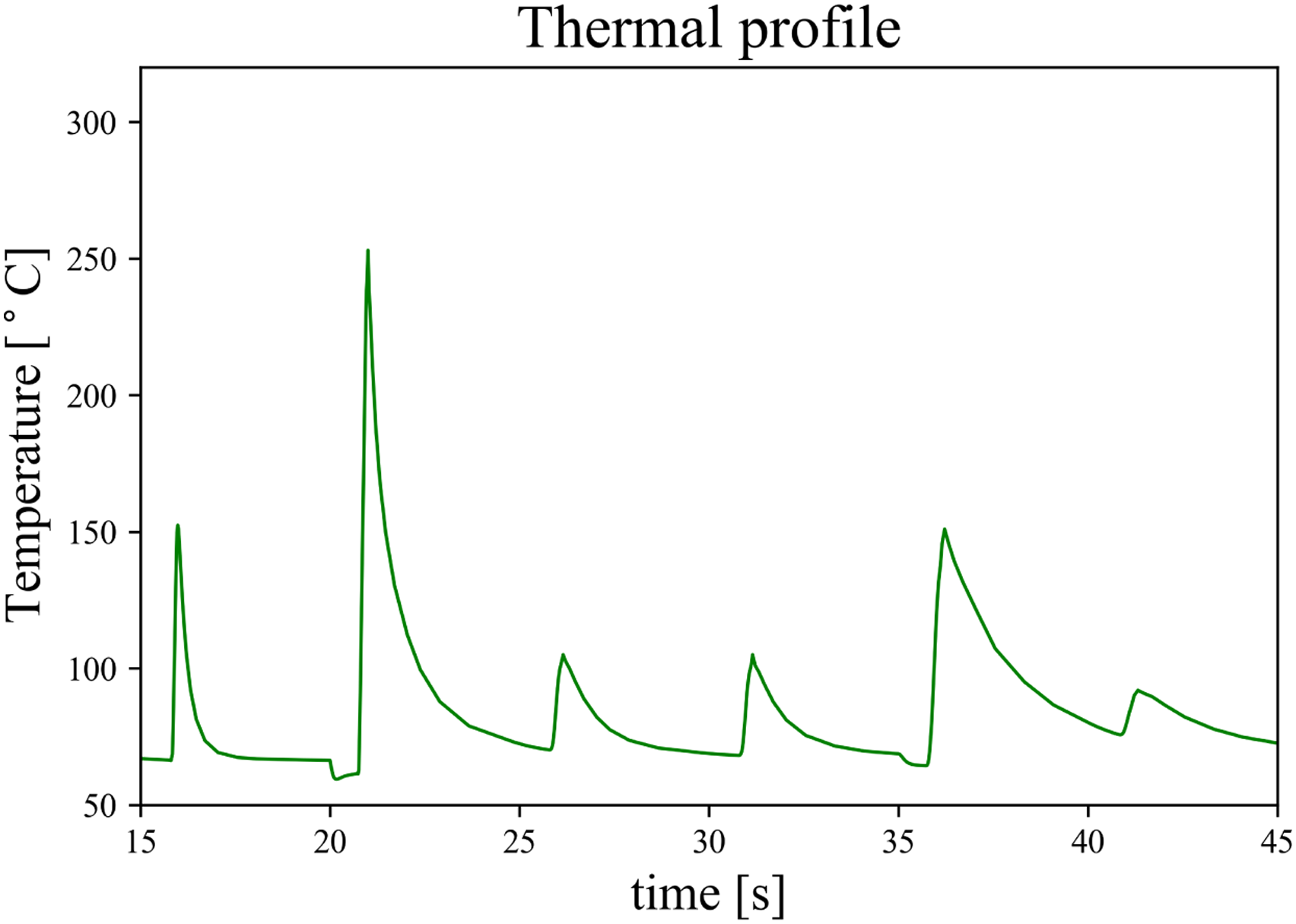
Experimental versus simulated thermal history
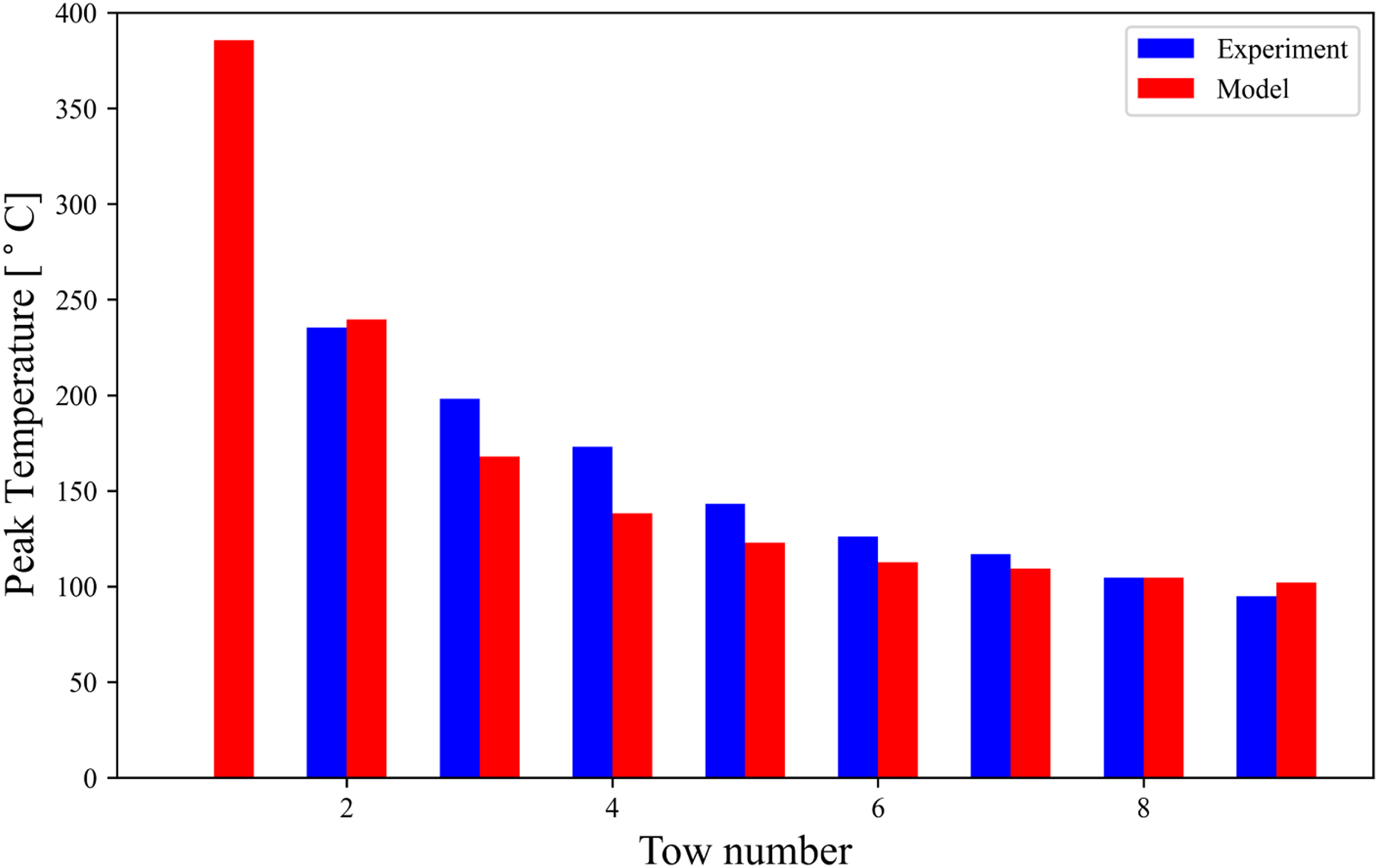
Comparison between the peak temperatures observed in FBG experiments and the process model is shown in Figure 18 and Figure 19. Figure 18 compares the process model temperatures with those obtained experimentally for the first set of experiments, i. e where the angled FBG sensor was aligned at an angle of 5°, while Figure 19 compares the same quantities for the second set of experiments, i. e where the angled FBG sensor was aligned at an angle of 15° to the central line, for the two cases of the single-tow laminate experiments. It can be seen in both Figure 18 and Figure 19 that a good correlation between the experimental and model peak temperatures is observed for both the set of experiments for the single-ply laminates. The root-mean-square deviation (RMSD) between the experimental and the simulated results for the first case is 7.3% while the RMSD for the second case is 11.4%. These results indicate the validity of the single-tow model as well as the experimental methodology. Comparison of the peak temperatures observed during the placement of different tows in the single-tow laminate between the process model and the FBG experiments conducted using the first angled sensor configuration (5°). Comparison of the peak temperatures observed during the placement of different tows in the single-tow laminate between the process model and the FBG experiments conducted using the second angled sensor configuration (15°).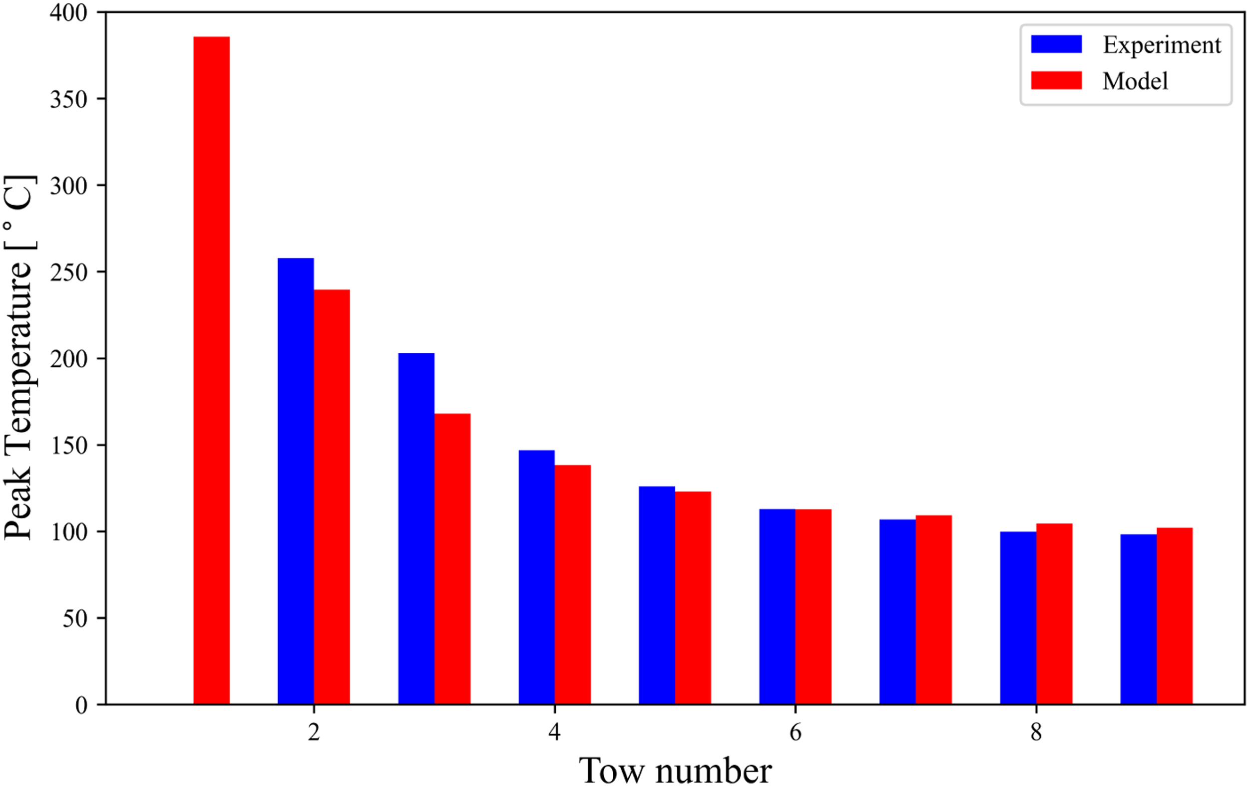
For the multi-tow laminate as well, the experimental results were compared with the corresponding temperatures extracted from the multi-tow model from the bottom of the middle tow in the lower ply. The comparison between the experimental and model results for the multi-tow laminate is shown in Figure 20. Comparison between the peak temperatures observed in the process model without considering heat input from adjacent tows and the FBG experiments conducted for the multi-tow laminate.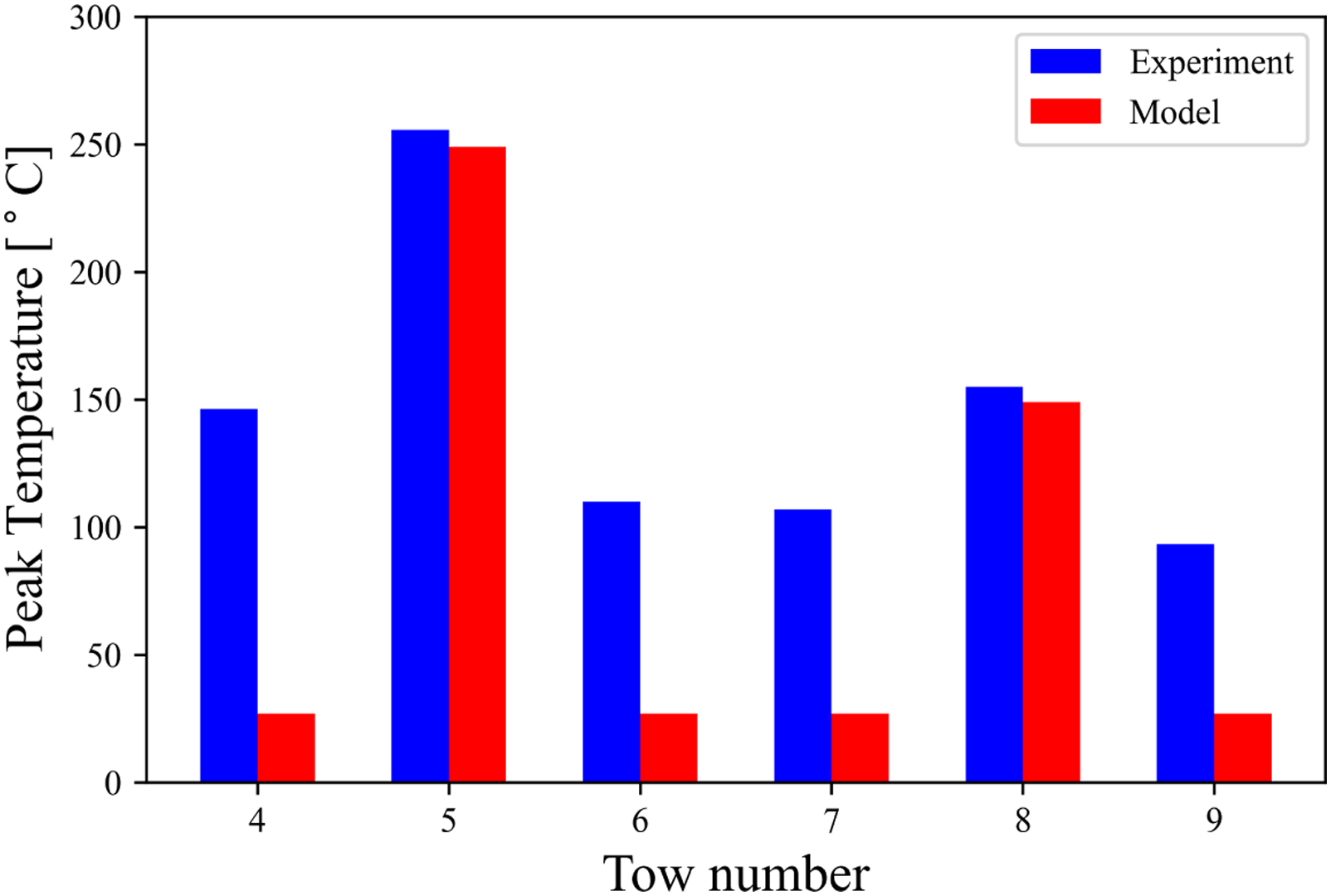
It can be seen that the experimental and model estimated temperatures agree only during the placement of the middle tow in each ply (i.e. when Tow-5 and Tow-8 are placed) and not when the tows on the sides are laid down in each of the plies (i.e. during the placement of Tow-4, Tow-6, Tow-7 and Tow-9). During the placement of these tows on the sides, the model predicts a temperature close to that of the ambient air which was set to 27°C. This discrepancy occurs because of how the heat flux is applied to the manufacturing process model. During the placement of any tow in the model, the heat flux is added to its bottom, as well as on top of the substrate. Only the substrate area immediately below the new tow is heated. The same procedure has been followed by most of the process models that exist in literature and this method works well for the case of a single-tow laminate. To accurately capture the effects of the HGT-based heating for the AFP composite manufacturing process, it is important that composite laminates having multiple tows in each ply are modelled and that the application of heat flux on the central as well as the adjacent regions of the laminate is applied appropriately.
To compare the predictions of the multi-tow model with experiments, the temperature was extracted from the bottom of the middle tow in the lowermost ply of the multi-tow laminate model. The peak temperatures observed in FBG experiments and the process model were compared as shown in Figure 21 and a good correlation can be observed. The root-mean-square deviation (RMSD) between the experimental and the simulated results is 3.4%. Due to the heat from the HGT on the adjacent tows, the induced peak temperature was found to be 153°C. Even if this temperature may not be enough to affect characteristics such as bonding and crystallinity development, it would affect the development of non-uniform residual stresses in the different regions of the laminate. Due to this, the heating of the adjacent tows in modelling the behaviour of AFP manufactured composites must be taken into account for an accurate estimation of the thermo-mechanics behaviour of the composite. Comparison between the peak temperatures observed in the FBG experiments conducted for the multi-tow laminate and predicted using the process model considering heat input on adjacent tows.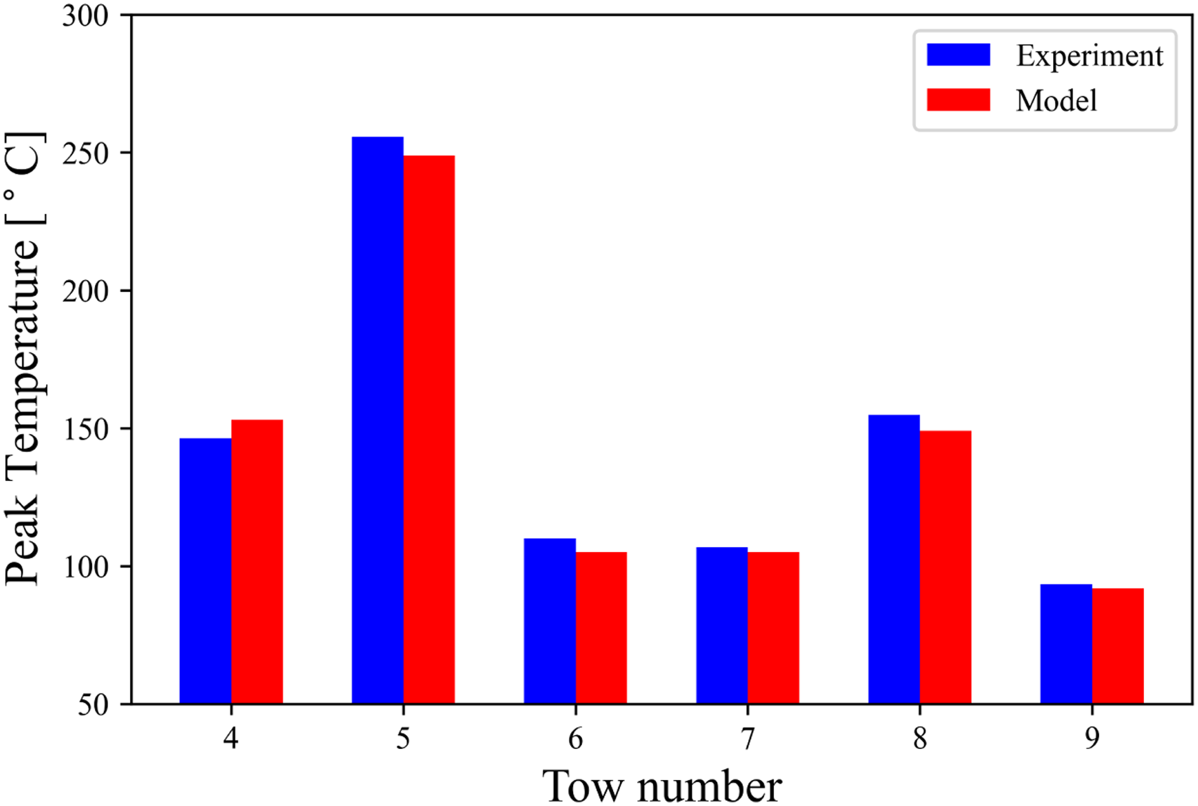
The multi-tow 3-D process model can be also used for planning the design of realistic and more complex composite components beyond the standardised coupons. There may be a temperature gradient along and perpendicular to the laid path in the substrate as well as the tool. This may be considered for planning the design of the tool path for producing complex geometries. The results may be different depending on the layup path sequence. In addition to the previously placed tows, the thermal history in different regions of the laminate will also depend upon the starting and endpoints of each path, the effect of which would be more prominent for 3-D composite components of non-standardised shapes. For several such path concentrations over a structure, such behaviour can also multiply which may also result in the occurrence of hot spots leading to material degradation. On the contrary, the existence of cold spots can also occur in certain regions and may result in localised insufficient bonding leading to defects. The thermal history would depend on the material deposition paths, whether linear or complex and should ideally be taken into account for developing an optimum deposition strategy for developing a composite component. Such a concept can be useful for future path generation algorithms for identifying critical areas in a component which may be prone to defect due to excess or lack of exposure to heat input for a considerable or insufficient time, respectively. This knowledge may aid in laying up a composite component with optimised performance with minimum defects. A variable material deposition speed may be required for complex geometries.
Conclusions and future work
A full-scale 3-D finite element model of the hot gas torch-based AFP manufacturing process was developed incorporating the effects of transient heat and pressure to study the interactions between the thermal and mechanical properties. The plies were modelled as independent parts and thermal and mechanical interaction properties were defined for all the contacts between tow surfaces. Heat transfer mechanisms were modelled and the prepreg tapes were subjected to natural convection on the exposed tow surfaces. Laminates having plies composed of both a single tow as well as multiple tows were simulated using the model both with and without considering the input heat effect on adjacent tows for comparison. For validating the model predictions, in-situ temperature measurements were successfully performed by conducting AFP manufacturing trials using different combinations of FBG sensors embedded between layers of a composite laminate. The model was found to correlate reasonably for single tow laminates. However, for multi-tow laminates discrepancies between prediction and measured results were observed. This is because of how the heat flux is applied to the manufacturing process models where the effect of input heat from the hot gas torch on the adjacent tows is not considered. The experimental testing made it possible to highlight the issues with the current state-of- the-art process models and allowed us to capture the effect of the non-uniform heating of the composite laminate during the placement of the prepreg tows. Heating of adjacent tows was shown to induce a temperature of 153°C which may result in the development of non-uniform residual stresses in the different regions of the laminate and must be taken into account for modelling the AFP composites manufacturing process for an accurate estimation of the thermo-mechanics behaviour of the component.
The model can also facilitate the study of the effect of tool heating and tool return time on the thermal history of the component. Tool return time has previously been studied for single tow laminates, but its effect can be better observed and can be expected to be more prominent in the case of multi-tow laminates. Tool heating can serve a dual purpose, it can increase the peak temperature in the laminate thereby improving bonding. It can also reduce the cooling rate thereby reducing the thermal gradients and the build-up of residual stresses in the laminate along with a reduction in material degradation. Future work can also consider the effect of the heating source touchdown as a result of which there may be excess heating in the substrate or tool at the beginning of a particular prepreg tow layup, and a thermal gradient may exist along the length of the prepreg tape being laid down. This may help in identifying critical hot spot locations which can henceforth be avoided. The model is also capable of studying the influence of different AFP process parameters such as the material deposition velocity and the input consolidation pressure on the resulting thermal history and thus the degree of bonding and interlaminar strength of resulting composites, which forms a part of the future work. A bonding model is being developed which will take the results from the 3-D model and predict the level of bonding in a composite laminate in different regions.
Footnotes
Declaration of conflicting interests
The author(s) declared no potential conflicts of interest with respect to the research, authorship, and/or publication of this article.
Funding
The author disclosed receipt of the following financial support for the research, authorship, and/or publication of this article: This work was supported by the Australian Research Council (IC160100040).
Appendix A Material properties.
References: 6,19,31,27,23,41,42 Temperature-dependent density and specific heat of APC-2 PEEK. Temperature-dependent elastic properties of APC-2 PEEK. Temperature-dependent thermal conductivity and coefficient of linear expansion of APC-2 PEEK tape. Relevant temperatures.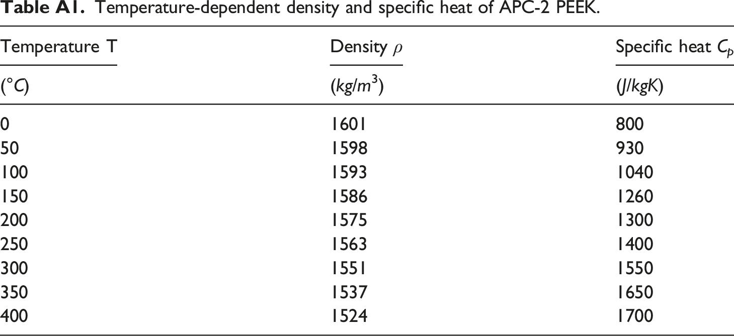
Temperature T
Density ρ
Specific heat C
p
(°C)
(kg/m3)
(J/kgK)
0
1601
800
50
1598
930
100
1593
1040
150
1586
1260
200
1575
1300
250
1563
1400
300
1551
1550
350
1537
1650
400
1524
1700
Temperature T
Elastic Modulus E11
Elastic Modulus E22=E33
Poisson’s ratio μ12 = μ13 = μ23
Shear Modulus G12 = G13
Shear Modulus G23
(°C)
(GPa)
(GPa)
—
(GPa)
(GPa)
23
130
10.3
0.32
6.00
4.80
65
130
9.6
0.33
5.43
4.34
121
130
8.3
0.32
4.86
3.89
168
127
4.3
0.34
2.51
2.01
182
126
4.3
0.34
2.16
1.73
232
125
3.6
0.40
0.95
0.76
288
125
1.7
0.40
0.53
0.43
315
124
0.6
0.40
0.23
0.19
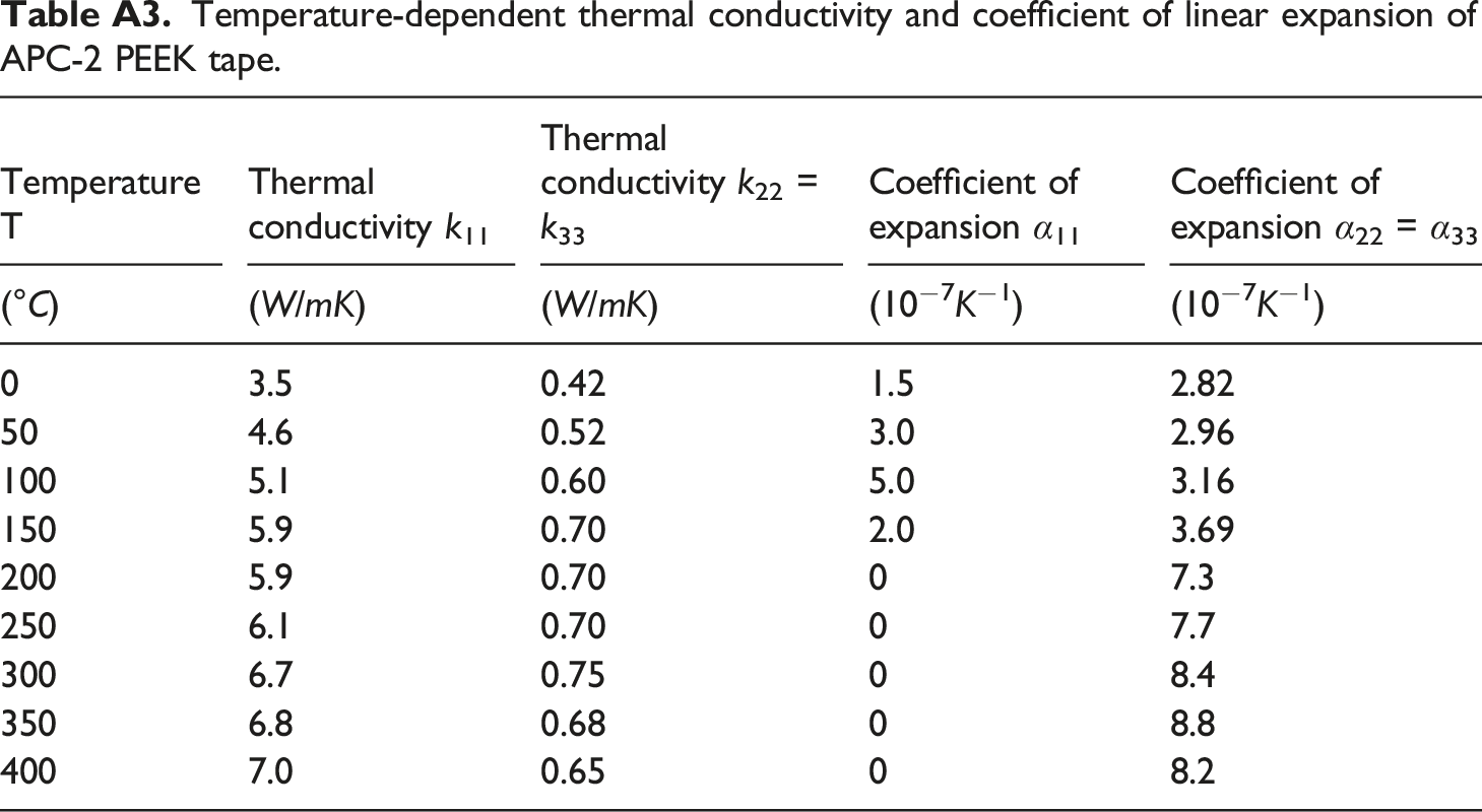
Temperature T
Thermal conductivity k11
Thermal conductivity k22 = k33
Coefficient of expansion α11
Coefficient of expansion α22 = α33
(°C)
(W/mK)
(W/mK)
(10−7K−1)
(10−7K−1)
0
3.5
0.42
1.5
2.82
50
4.6
0.52
3.0
2.96
100
5.1
0.60
5.0
3.16
150
5.9
0.70
2.0
3.69
200
5.9
0.70
0
7.3
250
6.1
0.70
0
7.7
300
6.7
0.75
0
8.4
350
6.8
0.68
0
8.8
400
7.0
0.65
0
8.2
Glass transition temperature
T
g
143 °C
Melting temperature
T
m
343 °C