
Abstract
Recent studies have proven the possibility of polymer sheet forming by incremental sheet forming (ISF) process, while there are limited studies on ISF of polymer matrix composites. Fiber-reinforced polymers (FRP) are significantly useful in industries due to their unique properties. In the current study, owing to the merits of ISF and the wide applicability of FRP, single point incremental forming (SPIF) of polyamide 6 (PA6) sheets reinforced by glass fibers (GF) is taken into account at various forming temperatures. In this regard, a fixture equipped with a ceramic infrared heating element was designed. The effect of some important parameters such as the volume fraction and orientation of fibers and the forming temperature on the formability, the thickness distribution, and the dimensional accuracy of PA6 and PA6/GF sheets is investigated. According to the results, an improvement in the formability of the composite sheet can be obtained using SPIF by increasing the forming temperature and decreasing the volume fraction of fibers. The formability of the composite sheet with the fiber orientation of [0/90] is far less than the one with unidirectional fibers. In the most of the successfully formed samples, the transverse compaction and the fracture of fibers at the part bottom, the buckling of fibers at the edge of the backing plate, and the draw-in of the sheet along the main direction of fibers can be detected. The thinning of the composite sheet is most affected by the volume fraction and orientation of fibers, while the forming temperature has the least effect. Moreover, the feasibility of SPIF of a circular flange with a wall angle of 90° from the composite sheet is assessed at elevated temperature.
Keywords
Introduction
Due to their unique properties like the high specific strength, stiffness, fatigue strength, and energy absorption capacity and also the excellent corrosion resistance and the lower installation, operating, and maintenance costs, fiber-reinforced polymer (FRP) composites have attracted much attention. 1 As a result, FRP composites are highly suitable for replacing conventional materials in different engineering applications. In general, FRP composites are categorized into two groups, namely, thermoplastic and thermoset composites. In addition to their recyclability, thermoplastic composites have higher toughness and flexibility than thermoset composites. So, they are more preferred in structures under static and fatigue loadings. 2 Depending on the production rate, the initial cost, the initial material, and the final size and shape of the sample, there are different ways to manufacture thermoplastic composites like thermoforming, tape winding, compression molding, autoclave process, diaphragm forming, and blow molding. 3
The incremental sheet forming (ISF) process is an emerging and flexible technique for rapid prototyping through which a flat sheet blank is deformed into a desired three-dimensional shape without the use of specific dies and punches. 4 The single point incremental forming (SPIF) is the most popular variant of the ISF process having the lowest initial cost and the highest flexibility. Nevertheless, SPIF suffers from some limitations such as a long forming time, a severe thinning, and a low dimensional accuracy. 5 Recent studies have proven the possibility of forming polymer sheets by SPIF. 6 Le et al. 7 investigated the effects of process parameters such as vertical pitch, the tool diameter, the feed rate, and the spindle speed on the SPIF of polypropylene (PP) sheets. The results revealed that an increase in the spindle speed and the tool diameter will result in a significant enhancement of the formability of polymer sheets. The influence of process parameters like the vertical pitch and the tool rotation on the SPIF of PLA and PVC sheets was studied by Davarpanah et al. 8 They indicated that in contrast to the SPIF of sheet metals, by increasing the vertical pitch, the formability of polymer sheets is improved, but the amount of the improvement is limited by the wrinkling phenomenon. Moreover, wrinkling is more likely to occur at a higher tool rotation. Bagudanch et al. 9 carried out a study on the influence of the process parameters including the tool size, the vertical pitch, the spindle speed, and the feed rate on the surface quality and the forming temperature in the SPIF of five different polymer sheets. They concluded that the spindle speed is the significant parameter affecting the forming temperature. Durante et al. 10 investigated the effect of contact conditions between the forming tool and the sheet and the tool path strategy on the formability, the twisting, and the elastic springback of PC sheets in the SPIF process. They reported that by utilizing an alternate tool path the formability increases and the twisting decreases. Additionally, it was claimed that the elastic springback decreases by using a fixed end tool and the tool path strategy has no effect on the springback. A study was conducted by Ambrogio et al. 11 to assess the effect of the spindle speed, the feed rate, and the initial temperature on the formability of PMMA sheets. The investigation revealed that the spindle speed and the initial temperature are the most effective parameters on the formability during SPIF.
Forming of composite sheets at room and elevated temperatures using conventional processes with dedicated dies has always been of interest. The forming limit diagram of recycled polymeric matrix composites was experimentally studied by Avila and Jabbur. 12 They found that these composites can support stress states from the pure shear to the biaxial tension at room temperature. Garnich and Klymyshyn 13 experimentally and numerically investigated the stamping process of a cone-shaped part from a woven composite with the thermoplastic matrix. They used a microscale FE model to predict room temperature thermoplastic prepreg tow properties for employing in a mesoscale FE model. It was indicated that wrinkling during die closure can be predicted using the simplified modeling scheme. Isogawa et al. 14 studied effects of the forming temperature and the blank holder pressure on the formability and the geometrical accuracy of PA66 matrix composite sheets reinforced by the carbon woven fabric in the deep-drawing process. They figured out that it is necessary to optimize the forming temperature and the blank holder pressure to prevent the wrinkling. Zhang et al. 15 focused on the experimental study and the finite element (FE) simulation of the deep drawing and the V-shape bending of carbon fiber-reinforced composites at elevated temperature. The results pointed out that the forming process is under the influence of the shearing mechanism. Effects of process parameters on the quality and geometrical accuracy of composite sheets with different matrix materials of ABS, PP, and PA6 reinforced by the carbon woven fabric in thermo-stamping process were investigated by Yin et al. 16 They stated that the reason behind the wrinkling of samples can be attributed to the forming temperature and the fiber orientation. Zal et al. 17 examined the influence of the layer arrangement and the forming temperature on the forming force and the springback of PVC matrix composites in a forming process. The results indicated that the lower the forming temperature is, the higher the springback will be. This is due to the fact that a high forming temperature activates the sliding mechanism and consequently the springback decreases. The deep-drawing ability of staple fiber organic sheets has been investigated by Goergen et al. 18 at elevated temperature. A FE model has been developed to predict the forming behavior of staple fiber organic sheets. It was found that a plastic deformation of up to 50% can be achieved. Ahn et al. 19 conducted a numerical study on some parameters like the fluid pressure, the boundary conditions, the blank shape, and the relief cuts in the thermo-hydroforming process of multilayer-reinforced composite blanks. It was shown that the wrinkling density and the wrinkling height can be reduced using the modified hydroforming process.
Among the above-mentioned processes for forming of polymer matrix composites, SPIF is more efficient for rapid prototyping and low-volume production. Limited studies have been conducted on the applicability of ISF in the forming of composite sheets. 20 Sanchez et al. 21 formed polymer matrix composite sheets reinforced by carbon nanotubes (f-MWCNTs) using the SPIF process. It was observed that the wrinkling on the cone wall is directly associated with the orientation of the forming tool movement. Moreover, they stated that the color variation between the inner and outer surfaces of the formed samples is due to the different stress states of each side. Davarpanah and Malhotra 22 investigated the effects of the layer thickness and the vertical pitch on the formability of the two-layer PA-AL5052 sheet in the SPIF process. They concluded that the formability is improved by increasing the thickness of the polymer layer, while decreasing the vertical pitch would limit the formability. The thickness of the metal layer has no effect on the formability of the composite sheet. Ambrogio et al. 23 used an electrical heater for heating the PA6 sheet reinforced by glass fibers (GF) to SPIF the truncated cone and hexagonal pyramid. The results of the investigation showed that an improvement of the geometrical accuracy of the part depends on the optimization of the thermal cycle. Chaparro et al. 24 examined the formability of the PMMA matrix composite sheet in the SPIF process by using the triacetine and Cloisite 30B as the reinforcements. The results revealed that the formability can be improved by adding the triacetine and Cloisite 30B. In order to heat the PA6 matrix composite sheet reinforced by GF, hot air was utilized by Obaidi et al. 25 They studied the relation between the forming time, the forming depth, and the working temperature. They concluded that by increasing the wall angle, the sheet is stretched more, which is necessary to achieve a successful part with a desired shape. Hou et al. 26 focused on forming a truncated pyramid from a biodegradable composite sheet using a thermal-assisted SPIF process. They found that for achieving a successful part, it is necessary to sandwich the composite sheet between an iron and an aluminum sheet. Also, it was shown that the tool path strategy and the thickness of the composite sheet have significant effect on the formability.
Regarding the literature reviewed above, the forming of polymer matrix composites is commonly carried out by conventional processes and accordingly implementing SPIF as an alternative process with particular advantages needs more investigation. In this paper, SPIF of a truncated cone from the polyamide (PA6) sheet and the polyamide matrix composite sheet reinforced by glass fibers (PA6/GF) is investigated at elevated temperatures. The PA6/GF composites are widely used in the automotive and aerospace industries, but their formability has been less studied. Unlike the previous studies, here, a multistage strategy is used to SPIF the composite sheet. The effects of the fabrication parameters of the composite sheet including the volume fraction of the reinforcement and the fiber orientation together with the important process parameter, that is, the forming temperature, on the formability, the thickness distribution, and the dimensional accuracy are experimentally investigated. To extend the application of the SPIF process to the forming of polymer matrix composites, the feasibility of hole flanging on the considered composite sheet is also assessed.
Material
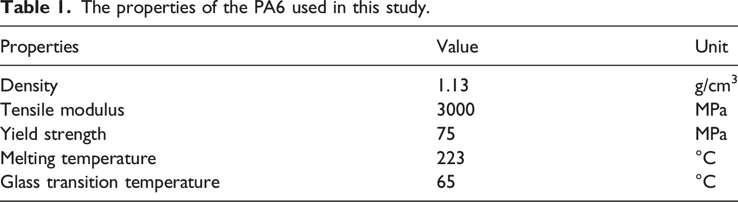
At first, using the hot press process shown in Figure 1(a), the polymer sheets with the thickness of 0.3, 0.4, and 2 mm were prepared from initial pellets of PA6. Before hot pressing, pellets of PA6 were preheated to 80°C for 4 h in an oven to dry them completely. The properties of PA6 used in this study are presented in Table 1. The utilized die set comprises two steel plates. The square frame with the dimension of 100 mm × 100 mm and the thickness equal to the one of the desired polymer sheet is placed between the two steel plates. As shown in Figure 1(b), the required heat was supplied by the four rod heating elements with the electrical power of 250 W and the diameter of 10 mm. A K-type thermocouple together with a temperature controller was used to measure and set the temperature of the die. (a) The scheme of the die set used to produce the polymer and composite sheets and (b) the die set and the temperature controller on the press machine. The properties of the PA6 used in this study.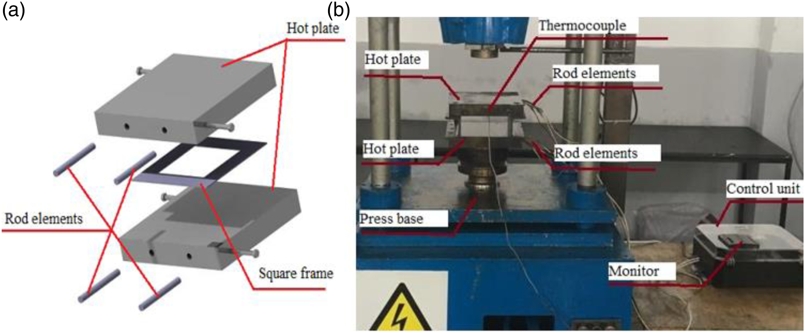
In this research, the PA6/GF composite sheet with the reinforcement volume fraction of 10% and 20% was fabricated. In this regard, unidirectional E-glass fibers were utilized. To study the effect of the fiber orientation on the SPIF process, the composite sheets with the orientations of [0]5, [0]3, [
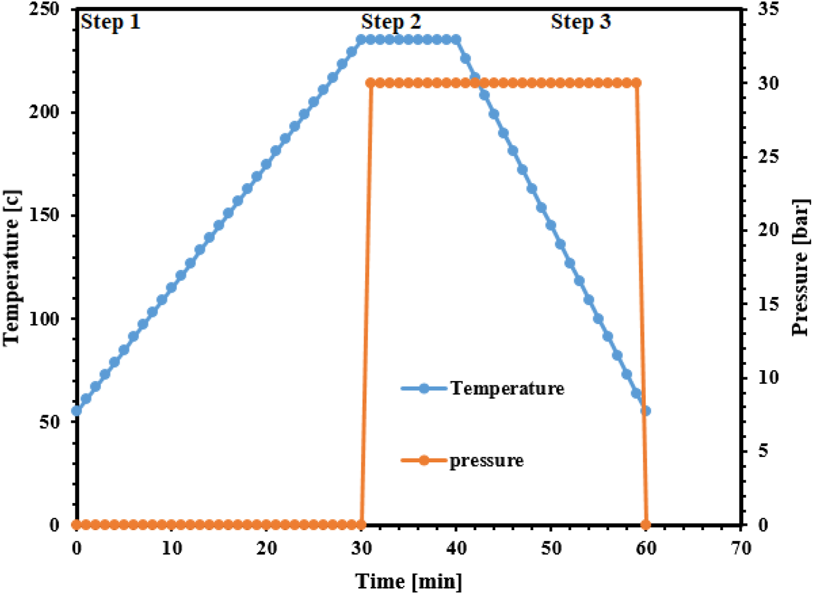
The heating cycle used in this study for the production of the polymer and composite sheets is shown in Figure 2. The heating cycle includes three stages as follows: 1. The heating stage: during this stage, either the initial pellets or the prepared polymer layers are heated to the temperature higher than the melting temperature (Tm) of the matrix without applying any pressure. 2. The stabilization stage: when the desired temperature is reached (i.e., 235°C), the pressure of 30 bar is applied to the die set. Keeping the temperature constant in this stage results in a better flow of the polymer melt and a complete filling of the die cavity. 3. The cooling stage: in the final stage, cooling is performed at the rate of 3°C/min. The cooling rate noticeably affects the microstructure and the residual stress level of the specimen. When the die temperature reaches the glass transition temperature (Tg), the applied pressure is released and the die is opened. The heating cycle used in producing the PA6 and PA6/GF sheets by means of hot press process. PA6: polyamide 6; GF: glass fibers.
Experiment of high-temperature SPIF
In Figure (3), the implemented equipment of the SPIF process at elevated temperatures for forming composite/polymer sheets is demonstrated. The equipment is placed on a three-axis CNC milling machine. Figure 3(b) shows the section view of the equipment. A ceramic infrared heating element with the maximum power of 500 W and the maximum temperature of 750°C was employed to supply the required heat. As displayed in Figure 3(a), the ceramic infrared heating element was fixed on the bottom of the forming fixture using an appropriate supporting block. In order to prevent heat loss, the ceramic infrared heating element was thermally isolated using an aluminum chamber and a glass wool blanket. A hemispherical head forming tool with the diameter of 15 mm was utilized. The spiral tool path with the feed rate of 1260 mm/min and the vertical pitch of 1 mm was considered. Under these process parameters, the FE simulations performed by Darzi et al.
27
showed that the equivalent plastic strain rate during the SPIF is in the range of 0.01–1 s-1. (a) The view of single point incremental forming process at elevated temperature for forming both composite and polymer sheets. (b) The section view of the implemented equipment.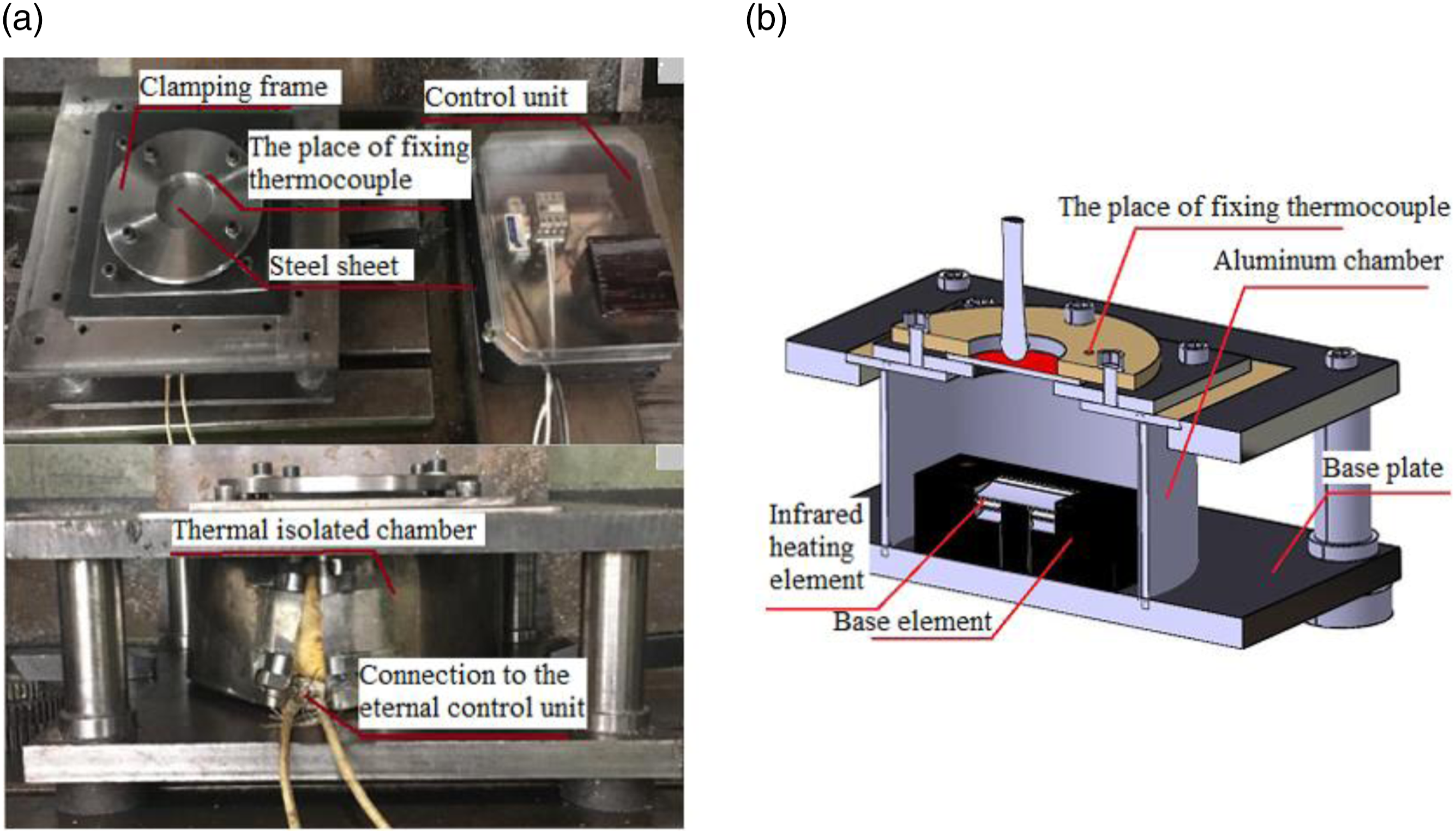
The primary experiments conducted on the polymer and composite sheets indicate that to obtain a successful part with an acceptable surface quality, the PA6/GF and PA6 sheets must be sandwiched between steel sheets and Teflon layers, as shown in Figure 4(a). The upper steel sheet is used to prevent the fiber movement associated with the friction between the tool and the composite sheet. The lower steel sheet is employed to achieve a homogenous heat distribution. The Teflon layers are necessary to prevent the steel sheets from sticking to the composite sheets. The layer arrangement for (a) main experiments and (b) determining the composite sheet temperature.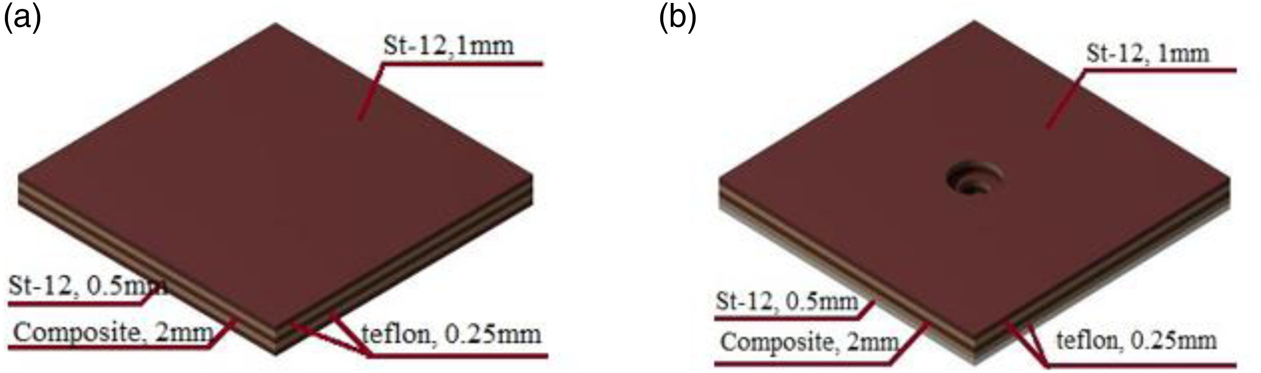
The temperature of the sheet during the SPIF process was measured using a K-type thermocouple. The location of the fixed thermocouple on the blank holder is illustrated in Figure 3(b). The thermocouple tip is in touch with the upper steel sheet. In this study, due to the presence of the steel sheets, the determination of the exact temperature of the composite or polymer sheet has been a challenge. To overcome this problem, a 16 mm hole was drilled at the center of the upper steel and Teflon sheets. A hole with the diameter of 9 mm was also drilled at the center of the composite or polymer sheets and the lower Teflon layer. As shown in Figure 4(b), the sandwiched layers were placed on the SPIF fixture and fixed by the blank holder. The temperature of the composite sheet and the upper and lower steel sheets were separately measured by another thermocouple at three different temperature levels and compared with the one obtained by the thermocouple directly attached to the blank holder. As expected, due to the thermal gradient along the thickness of the sandwiched layers, the temperature of the lower steel sheet was higher than the one of the composite sheet. This temperature difference was about 35°C on average. Also, the temperature difference between the upper surface of the composite sheet and the upper steel sheet was less than 5°C and the temperature difference between the center of the upper steel sheet and the one measured by the attached thermocouple was less than 2°C. Therefore, it can be said that the set temperature value on the controller is associated with the temperature of the upper surface of the composite sheet. The SPIF process was performed at the three temperatures of 75°C, 115°C, and 165°C.
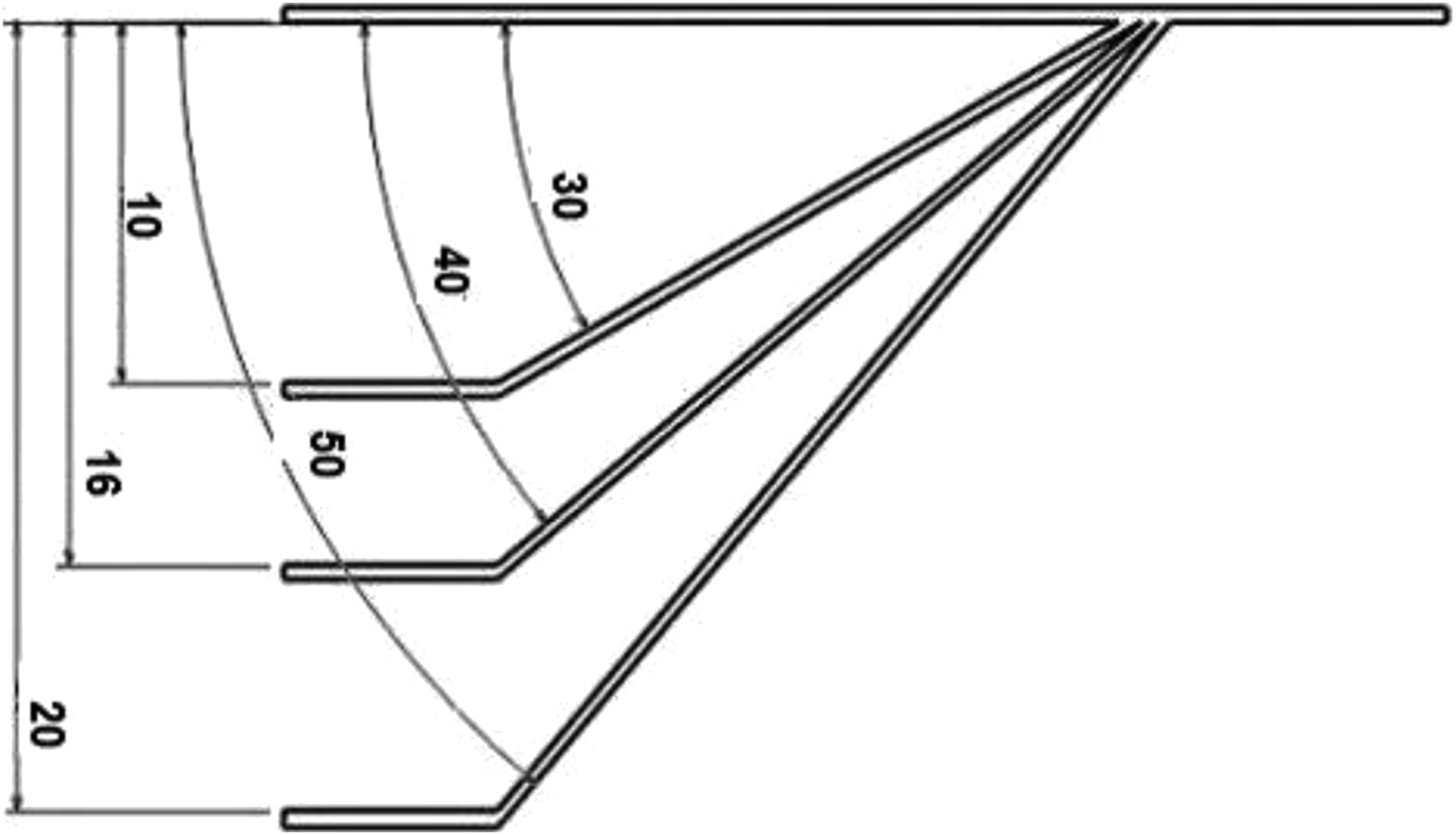
In this study, the SPIF of a truncated cone and a circular flange of the composite and polymer sheets with the dimensions depicted in Figure 5 is considered. The primary experiments on the SPIF of the truncated cone revealed that a slight bulge is formed at the center of the composite and upper steel sheets due to the presence of the supporting steel sheets. As a result, the sheet in the deformation zone is folded over the hemispherical head tool, which leads to a premature fracture of the upper steel sheet and consequently the forming process should be stopped. As shown in Figure 6, to reduce the local deformation under the forming tool, a three-stage forming strategy was used. The circular flange was formed using the single-stage forming strategy. In this regard, firstly, a circular hole was drilled at the center of the composite sheet with a certain diameter. The diameter of the hole determines the height of the flange edge. The geometries studied in this paper: (a) the truncated cone and (b) the circular flange (dimensions are in mm). The three-stage forming single point incremental forming strategy (dimensions are in mm).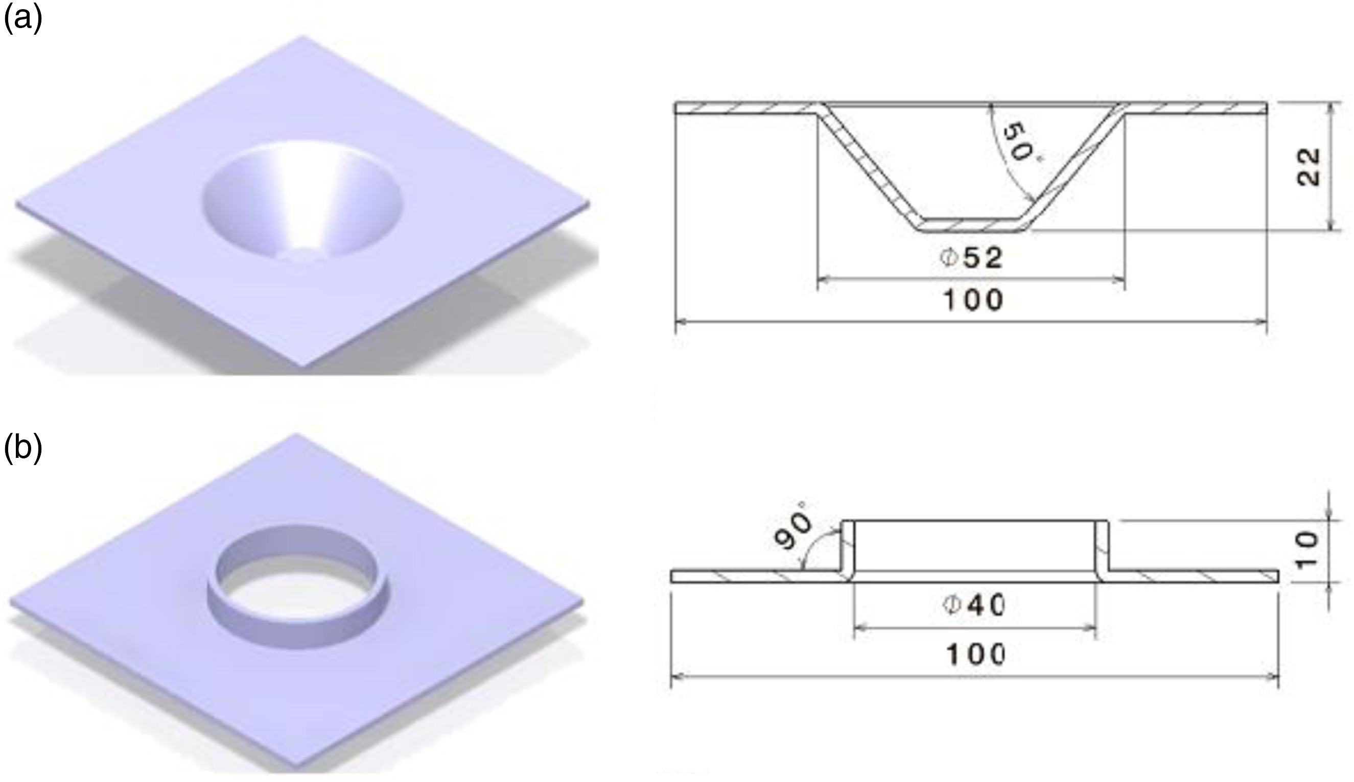
For measuring the thickness distribution, the considered samples were cut radially. The thickness of the samples was measured by means of a micrometer equipped with ball heads with an accuracy of 0.01 mm. Moreover, a profile projector device with an accuracy of 0.001 mm was used to investigate the dimensional accuracy of formed samples.
Results and discussion
Cold SPIF of the PA6 and PA6/GF composite sheets
At first, the possibility of forming the prepared sheets at room temperature was examined. It was concluded that because of the high brittleness, forming the composite sheet at room temperature is not feasible. As can be seen from Figure 7(a), firstly, fibers fracture due to the lower fracture toughness of the reinforcement than that of the matrix. Then, the separation between the fibers and the matrix happens and eventually, fracture in the matrix occurs. As shown in Figure 7(b), it is not possible to SPIF the PA6 sheets at room temperature because of its high brittleness. The cold SPIF of (a) the PA6/GF composite with the fiber orientation of [0] and the volume fraction of 10% and (b) the PA6 polymer sheet. SPIF: single point incremental forming; PA6: polyamide 6; GF: glass fibers.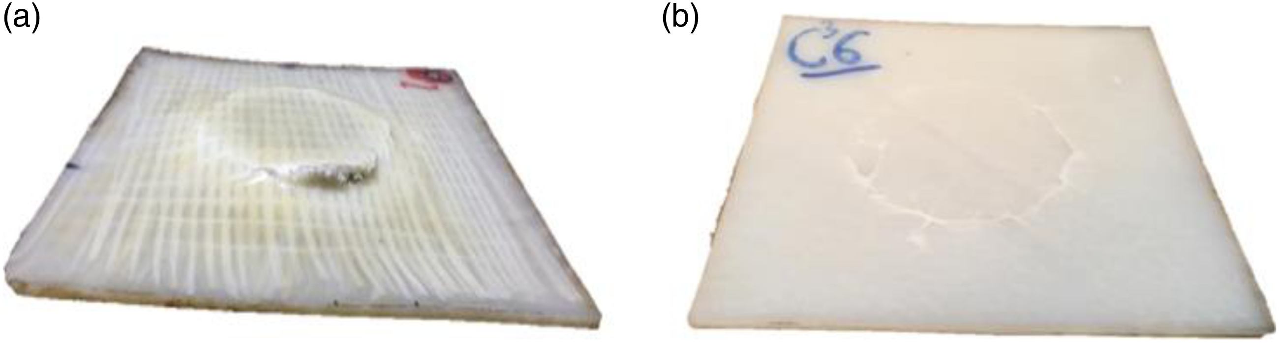
Common defects of SPIF at elevated temperatures
The observed defects in SPIF of the composite sheet at elevated temperature include the sheet burning, the fiber movement, the part distortion, and the fiber buckling, which are explained as follows.
Figure 8 shows a formed composite sheet without using the supporting steel sheet of Figure 4. As obvious from Figure 8, the absence of the supporting steel sheets results in burning of the lower surface of the composite sheet and the fiber movement at the upper surface of the composite sheet. Thus, the use of the lower steel sheet is vital to apply a uniform heat to the lower surface of the composite sheet. There is friction between the forming tool and the upper surface of the composite sheet. The friction causes not only the fiber movement, but also the accumulation of the matrix ahead of the forming tool. To avoid the direct friction, the upper supporting sheet should be used. So, the use of the supporting sheets prevents the ploughing of the composite sheet and the fiber movement. The defects due to the absence of supporting steel sheet in: (a) the lower surface and (b) the upper surface of the composite sheet.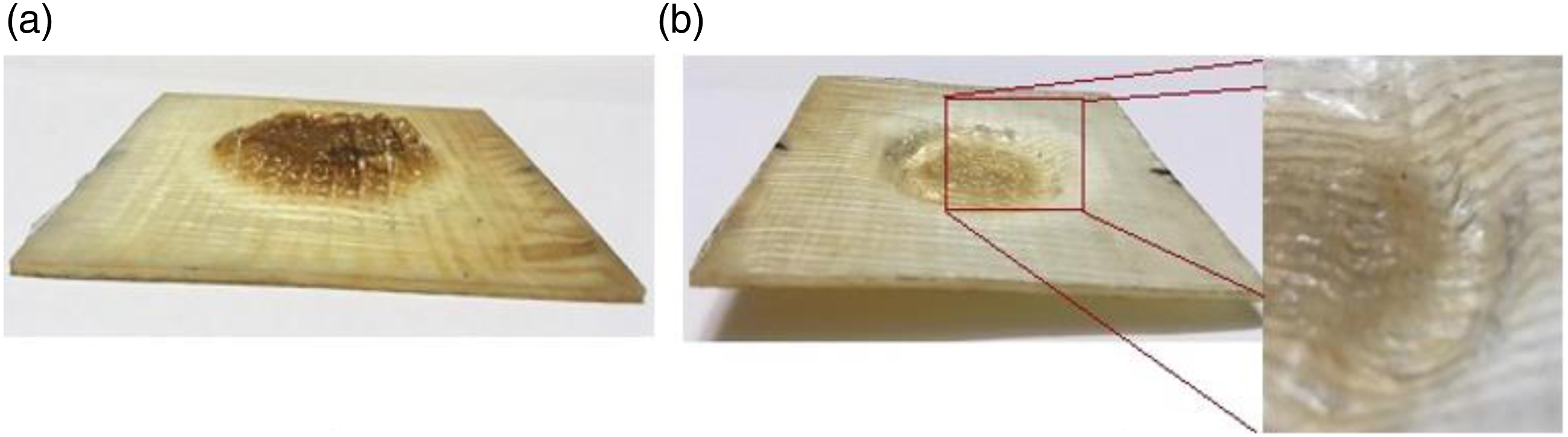
Generally, temperature changes during a forming process at elevated temperatures induce thermal distortion in a final sample. Figure 9 compares the two samples with the fiber volume fraction of 10% and the fiber orientation of [0,0] formed at the temperature of 165°C. Figure 9(a) depicts the difference between the edge height of the two samples in which the distortion is obvious. In order to reduce this defect, after the SPIF process, sufficient time should be given to the part such that the temperature of its matrix cools down to Tg and then the formed part can be unloaded. Figure 9(b) illustrates the distortion-free sample formed under the above-mentioned conditions. The comparison of samples with the volume fraction of 10% and the fiber orientation of [0] at the temperature of 16°C: (a) with distortion and (b) without distortion.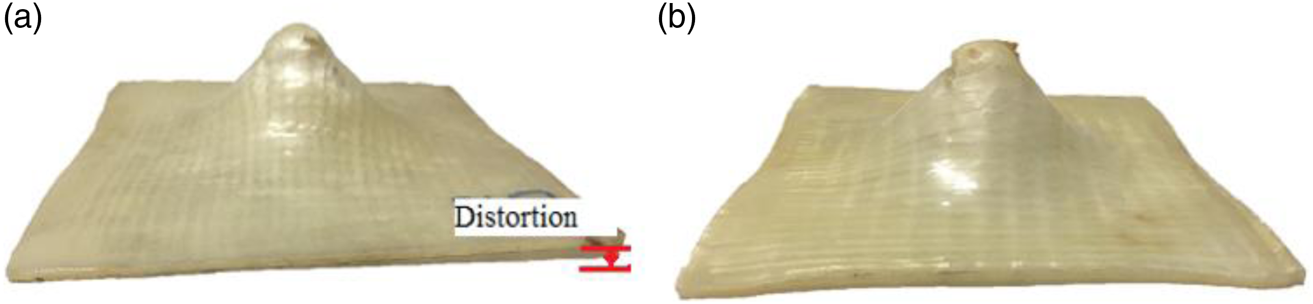
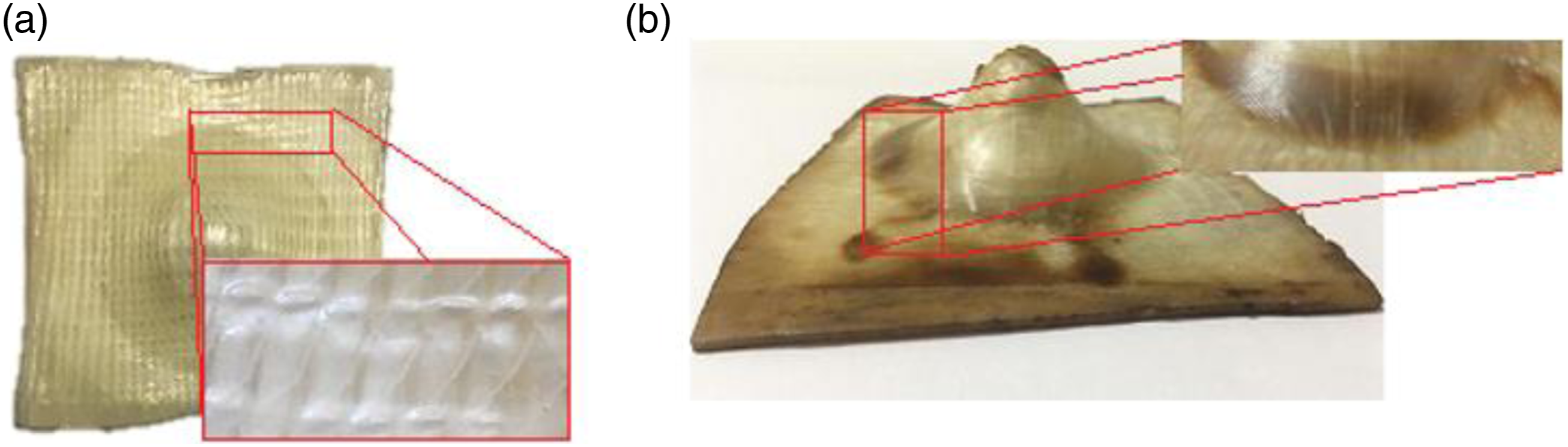
The fiber buckling was observed in the vicinity of the circular hole of the backing plate, as shown in Figure 10(a). Figure 10(b) shows an optical microscope image with a magnification of 8× in which the fiber wrinkling is observed as consecutive dark short lines. The occurrence of this phenomenon can be attributed to not only the relative sliding of the parallel fiber strings, but also the sliding of the composite layers during the SPIF process, which results in a bigger shear angle between fibers. The compression of fibers along the horizontal direction and the pressure resulting from the matrix movement within the space between the fibers are the other reasons of appearing of a non-uniform surface with wrinkling.
28
The fiber buckling in the SPIFed sample with the volume fraction of 20% and the fiber orientation of [0] at the temperature of 165°C in (a) macroscopic and (b) microscopic views at the wrinkling area.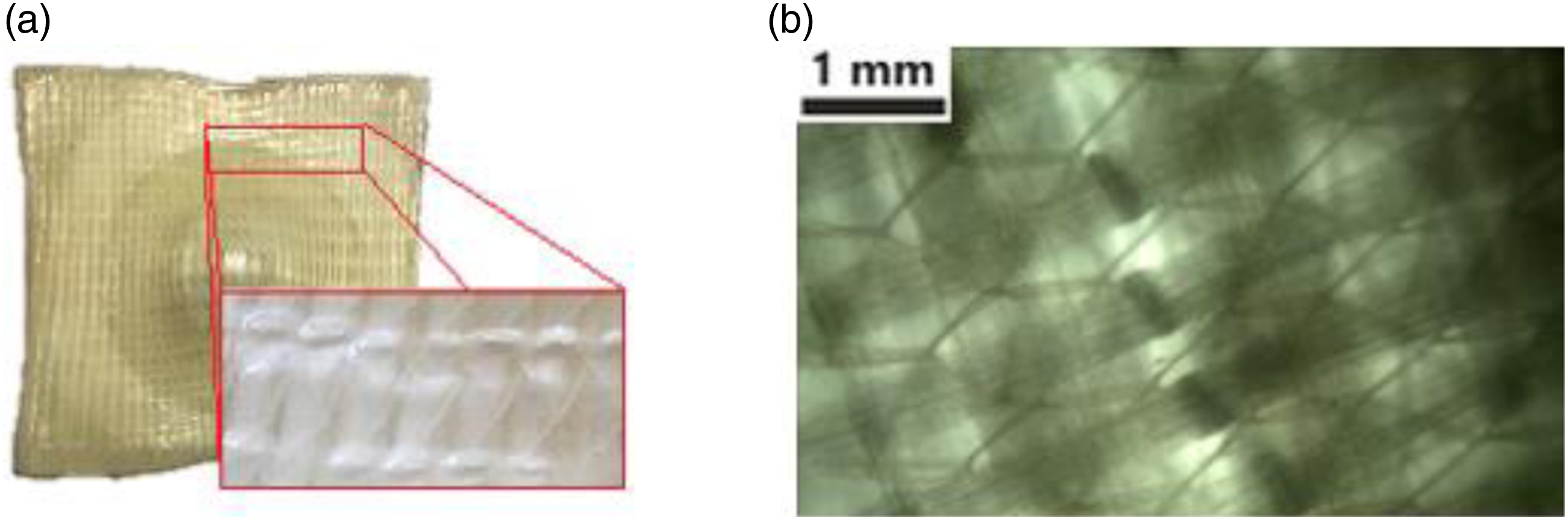
SPIF of the PA6 sheet at elevated temperatures
The SPIF process of the PA6 sheet was studied at three different temperatures of 75, 115, and 165°C. As previously mentioned in Section (3), the multistage strategy shown in Figure 6 was utilized. Figure 11 shows the samples formed at the considered temperatures. It can be inferred from the comparison of Figure 7(b) with 11 that an increase in the forming temperature would result in a noticeable increase in the formability. The specimen shown in Figure 11(a) was fractured at the height of 21 mm in the third forming stage under the temperature of 75°C. While, under the two other temperatures, the specimens were formed up to the desired height, as illustrated in Figures 11(b) and (c). It can be concluded that if the forming temperature of the PA6 sheet is higher than Tg (Table 1), the forming depth would be significantly enhanced. As seen in Figure 11(c), the color of the sample was changed due to the high forming temperature of 165°C. The hot SPIF of PA6 sheet at the temperature of: (a) 75°C, (b) 115°C, and (c) 165°C. SPIF: single point incremental forming; PA6: polyamide 6.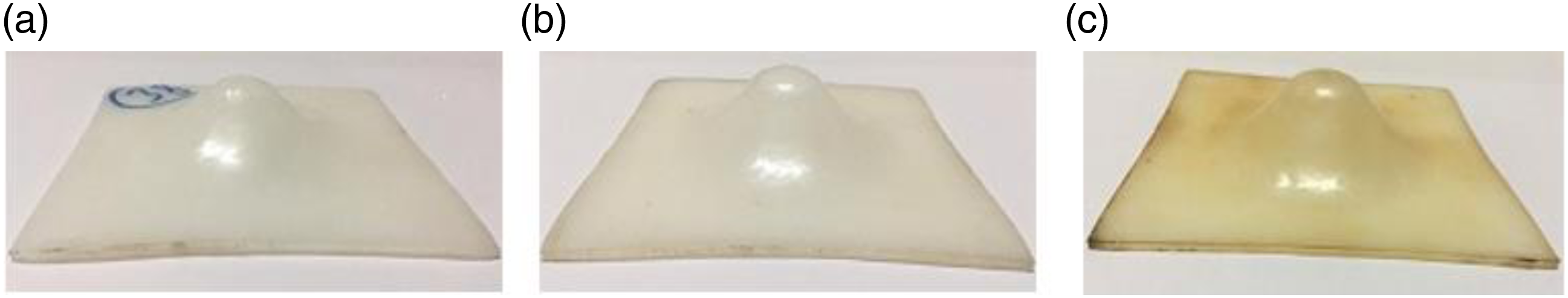
For the further investigation of the temperature effect, the thickness distribution of the two samples successfully formed at 115°C and 165°C is compared in Figure 12(a). As seen, the thickness distribution is not affected by the forming temperature and the location of the maximum thinning is almost the same for the different temperatures. The forming temperature has a significant effect on the thinning such that by increasing the temperature from 115°C to 165°C, the maximum thinning increases by 30%. At the temperature of 165°C, fracture happened in the upper steel sheet at the tip of the cone. As a result, due to the thinning, the polymer was extruded from there during the forming process. A comparison between the designed and formed geometry for the two considered temperatures is shown in Figure 12(b). A noticeable deviation between the designed and formed geometries is observed at the lateral wall of the samples close to the large diameter of the truncated cone. This deviation is mostly related to the effect of the bending around the edge of the backing plate. By increasing the diameter of the forming tool, the amount of bending increases. The deviation in the small diameter of the truncated cone can be attributed to the diameter of the forming tool. As seen, the increase of the forming temperature has a significant effect on the bending around the large diameter of the truncated cone. An obvious difference in the forming depth can be observed between the designed and formed profiles. This is due to the shrinkage of the material after cooling from the forming temperature. The effect of temperature on (a) the thickness distribution and (b) the geometric profile of the SPIFed PA6 sheet with the wall angle of 50°. SPIF: single point incremental forming; PA6: polyamide 6.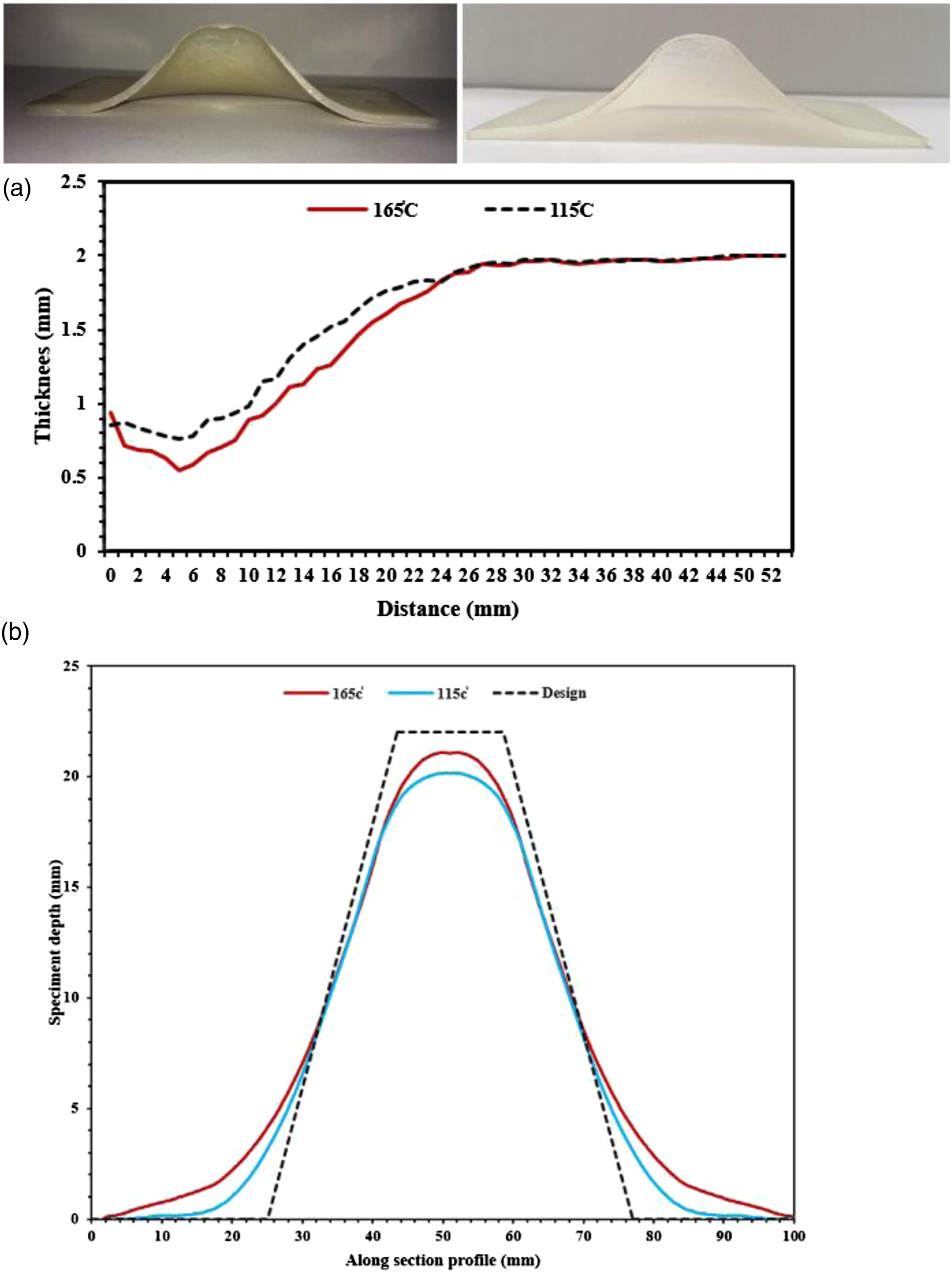
SPIF of the PA6/GF composite sheet at elevated temperatures
It should be noted that a number of deformation mechanisms can be identified during composites forming. These mechanisms have been well summarized by Long.
28
The SPIF of the composite sheet at elevated temperatures was investigated using 12 experiments with the two different volume fractions, the two different fiber orientations, and the three temperatures. Unlike the SPIF of the polymer sheet, under the considered conditions, it is not possible to successfully form the truncated cone with the wall angle of 50° and the forming depth of 22 mm. All specimens were fractured in the third forming stage at different depths. Due to the presence of the supporting steel sheets, the exact determination of the fracture depth was not possible. Therefore, the fracture depth of each specimen was approximately determined using several experiments by incrementally increasing the forming depth by 1 mm. Figure 13 shows 50° cones from the composite sheet with different fracture depths. It seems that fracture firstly occurred in the fibers, then the separation of fibers and the matrix was happened, and eventually the matrix fractured. Figure 14 compares the fracture height of composite specimens failed in the third forming stage. The specimens formed at the temperature of 75°C were fractured sooner than those formed at the other temperatures in the second forming stage, and so the corresponding results are not presented in Figures 13 and 14. The conical samples made of the composite sheet in the third forming stage with the wall angle of 50°. The comparison of the fracture height of the composite samples in the third stage with the volume fraction of: (a) 10% and (b) 20%.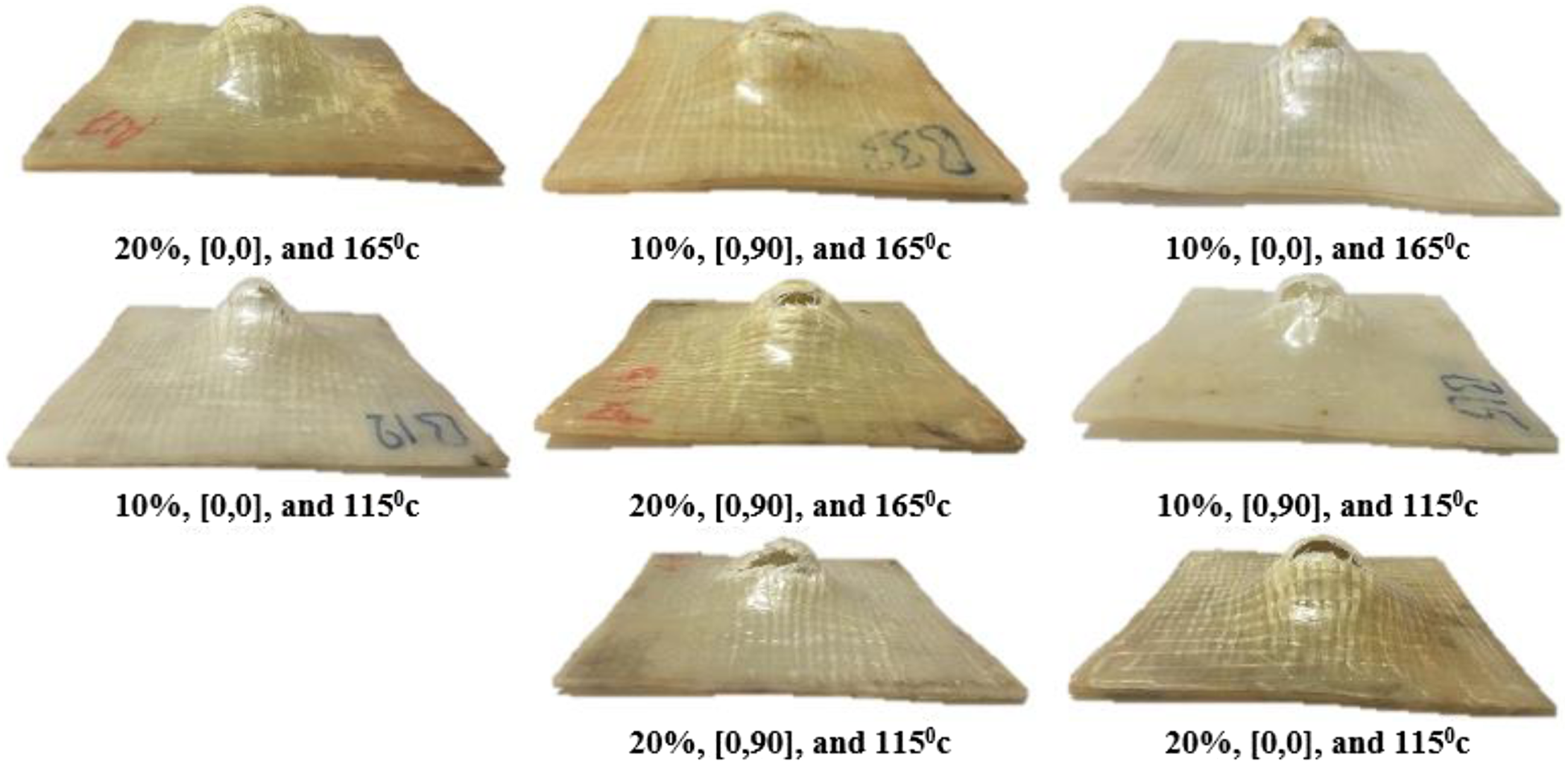
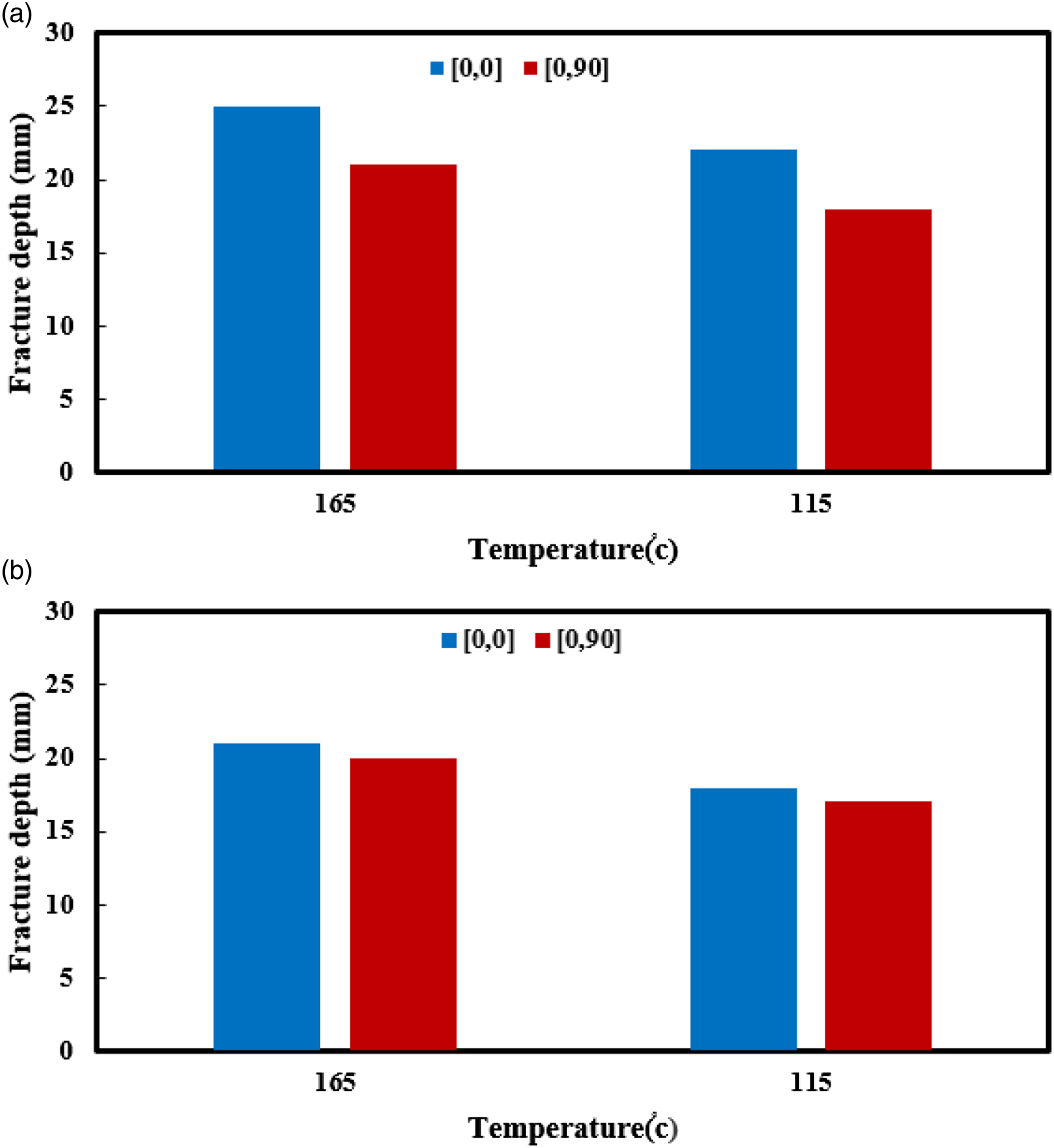
As seen in Figure 14, the formability of the composite sheet with the fiber orientation of [0] is much better than the one with the fiber orientation of [0/90]. The comparison of Figures 14(a) and (b) indicates that the forming depth increases as the volume fraction decreases. As reported by Liang et al., 29 with an increase in the reinforcement volume fraction the tensile modulus and the strength of the composite material increase, while the formability decreases. According to Okada et al., 30 rising the forming temperature leads to the matrix softening and consequently results in an improved material formability. It is possible to reach the desired geometry at higher temperatures because of the activation of the sliding mechanism, according to Zal et al. 17
For further study of the effect of the parameters on a specimen without defects, a truncated cone with the wall angle of 40° and the height of 18 mm was considered as shown in Figure 13. The SPIF process was performed using a two-stage strategy involving the intermediate shapes with the wall angles of 30° and 40°. At the temperature of 75°C, which is close to the Tg of the matrix, the composite sheet showed a relatively low formability and as a result was not completely formed in the second stage. As indicated in Figure 15, due to the lower flexibility of the matrix, fibers cannot flow freely and therefore are fractured at the temperature of 75°C. The sample with the wall angle of 40° and the volume fraction of 10% and the fiber orientation of [0] at the temperature of 75°C.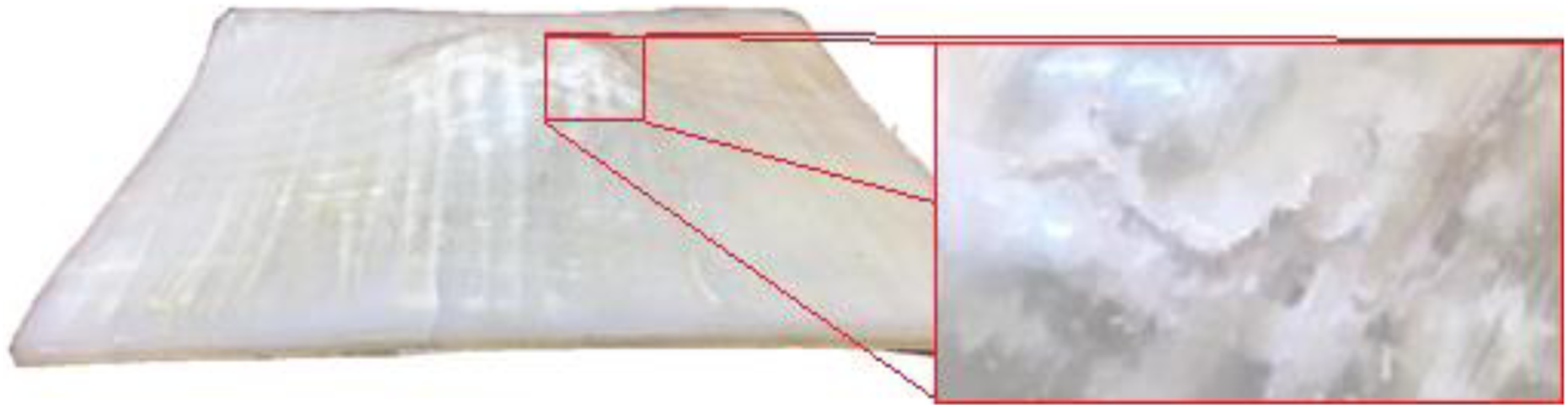
Figure 17 shows the specimens with the wall angle of 40° from the composite sheet formed at the temperature of 115°C and 165°C using the two-stage strategy. All samples, except the one with the fiber orientation of [0/90] and the volume fraction of 10%, have successfully formed up to the height of 18 mm. The mentioned specimen was fractured at the temperature of 115°C and the height of 15 mm. The samples shown in Figure 16 contain defects which are separately described below. Generally, the fiber wrinkling around the hole of the backing plate occurred in all specimens. The level of wrinkling in the specimen #1 formed at the temperature of 165°C is qualitatively lower than those formed at lower temperatures like the specimens #2. In order to completely remove the defect, increasing the forming temperature up to the melting temperature of the matrix is suggested. Figure 17 indicates the effect of the temperature on the fiber wrinkling. As obviously shown in Figure 17(b), the wrinkling defect was completely removed at the temperature of 200°C. But, on the contrary, burning and compression of the composite sheet along the thickness direction occurred. The composite samples with the wall angle of 40° produced by the two-stage single point incremental forming process. The wrinkling around the circular hole of the backing plate at the temperature of: (a) 165°C and (b) 200°C.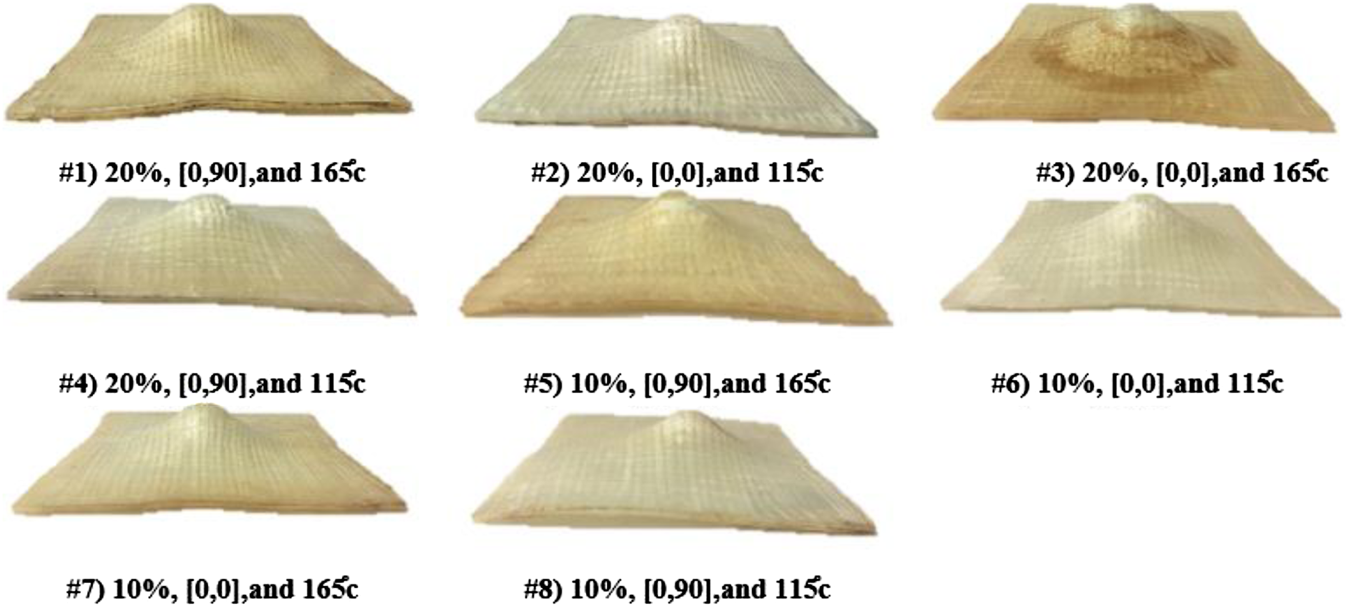
In the specimen #3, the flattening and rupture of the fiber can be seen at the bottom of the cone. In the specimen #4, firstly, the fiber was fractured. Then, after the separation of the fiber and the matrix, the matrix was fractured. Generally, in the specimens with the volume fraction of 10%, the fiber flattening was observed. The specimen #1 can be considered as a sound part with the lowest wrinkling and without the fiber flattening and fracture.
Figure 18 illustrates the material draw-in of the formed samples. The material draw-in is attributed to the flow of the sheet into the hole of the backing plate. This phenomenon is considered integral to obtain a sample with desired shape. As seen in Figures 18(a) and (b) for the truncated cones with the wall angle of 30° and 50°, by increasing the wall angle, the amount of the sheet draw-in increases. By comparing Figures 18(c) and (d), it can be concluded that the specimen with the fiber orientation of [0] experiences more draw-in than the one with the fiber orientation of [0/90]. This can be associated with the use of the unidirectional fibers in the specimen with the orientation of [0]. In Figures 18(e) and (f), the effect of the volume fraction of 10% and 20% on the amount of the draw-in is presented. It can be concluded that the specimen with the volume fraction of 20% experiences more draw-in than the one with the volume fraction of 10%. The effect of the wall angle, the fiber orientation, and the volume fraction on the draw-in: (a) 20%, [0,0], 30°, (b) 20%, [0,0], 50°, (c) 10%, [0,90], (d) 10%, [0,0], (e) 10%, [0,90], and (f) 20%, [0,90].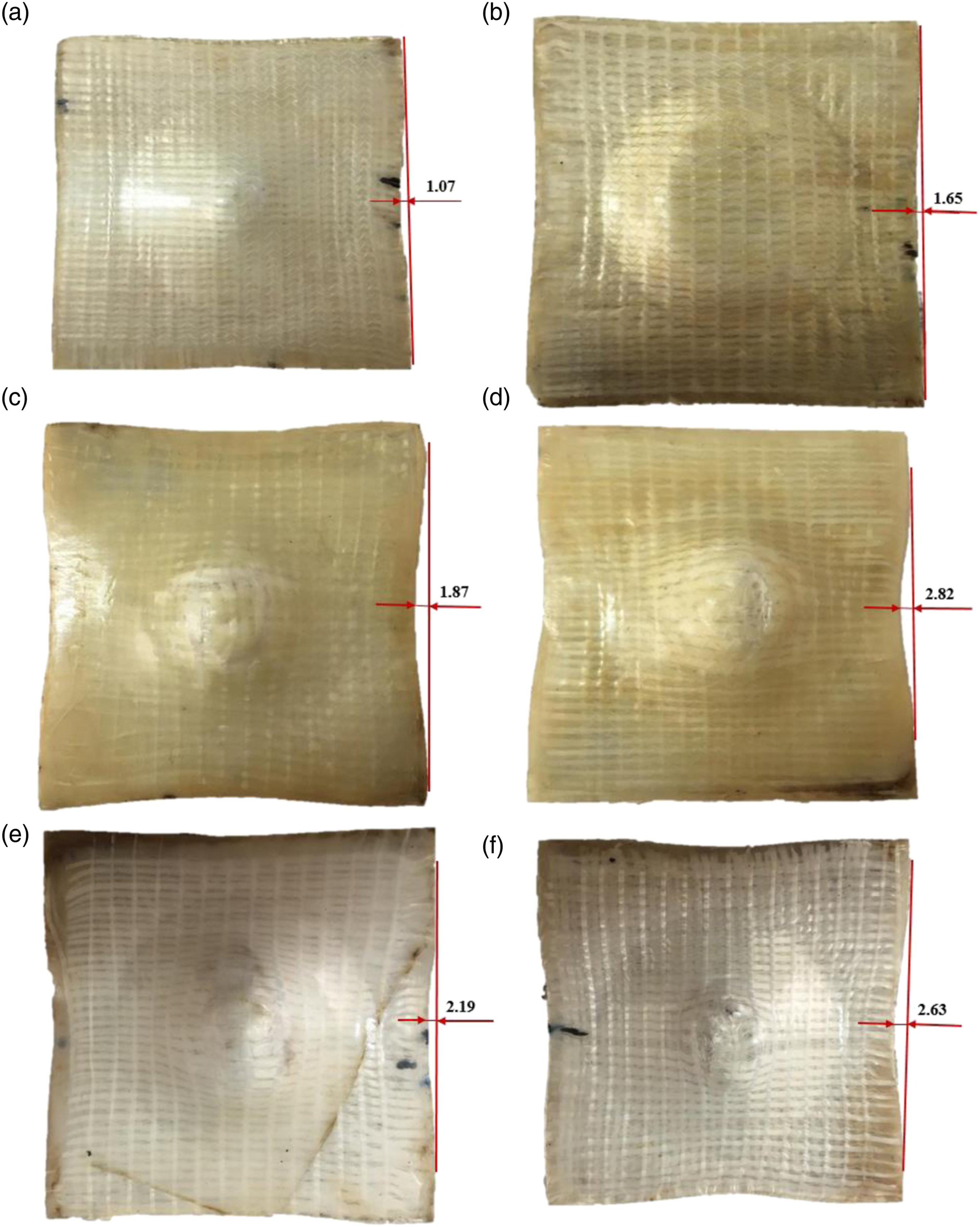
Thickness distribution and dimensional accuracy in SPIF of PA6/GF composite sheets
Some successful specimens were selected from the ones presented in Figure 16 to investigate the thickness distribution, as depicted in Figure 19. According to Figure 19, a reduction in the thickness of the flange zone is observed. From the free edge of the sheet toward the hole of the backing plate, the amount of thinning decreases. There is a sharp reduction in the thickness in the area close to the tip of the specimens. Finally, the amount of thinning suddenly decreases and the thickness of the specimen slightly increases at the tip of the cone. The reason for the final thickening can be attributed to the material flow as a result of the tool movement and the accumulation of the material at the tip of the specimen. The thickness distribution in the formed conical samples with the wall angle of 40°: (a) the composite samples with the volume fraction of 20% and the fiber orientation of [0], (b) the composite samples with the volume fraction of 10% at the forming temperature of 165°C, and (c) the composite samples with the fiber orientation of [0] at the forming temperature of 115°C.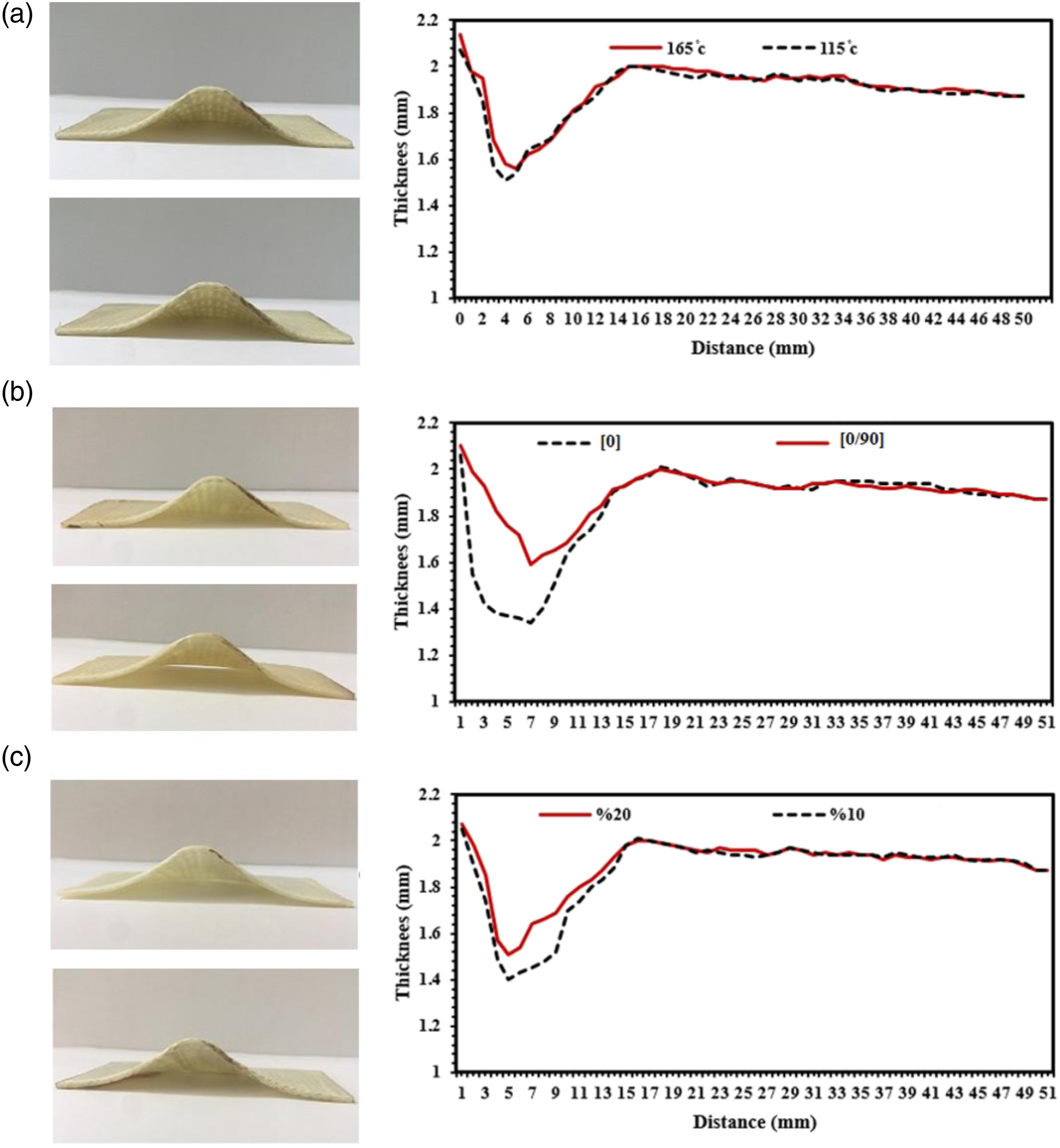
Figure 19(a) represents the effect of the temperature on the thickness distribution of the composite specimen with the volume fraction of 20% and the fiber orientation of [0]. Unlike the polymer specimens represented in Figure 12, the effect of the temperature is negligible such that by increasing the temperature only a reduction of 3% in the maximum thinning is observed. Figure 19(b) illustrates the effect of the fiber orientation on the thickness distribution of the specimen with the volume fraction of 10% formed at the temperature of 165°C. The maximum thinning in the specimen with the fiber orientation of [0] is 18% higher than the one with the fiber orientation of [0/90]. In Figure 19(c), the effect of the volume fraction on the thickness distribution of the composite specimen with the fiber orientation of [0] formed at the temperature of 165°C is depicted. As shown, the maximum thinning increases by 9% when the fiber volume fraction decreases.
Figure 20 illustrates the effect of both the volume fraction and the fiber orientation on the dimensional accuracy of the selected specimens shown in Figure 16. By comparing the formed specimens with the designed profile, a significant geometric deviation can be observed specifically in the wall of the specimens. Moreover, there is a difference in the forming depth between the designed profile and the formed specimen. This is because of using a 15 mm diameter forming tool which is larger than the small diameter of the designed cone. The dimensional accuracy is highly affected by the thermal residual stress and the material shrinkage after cooling to room temperature. As seen in Figure 20, the effect of the volume fraction on the dimensional accuracy is much more than the effect of the fiber orientation. The dimensional accuracy of the formed composite samples with the wall angle of 40°: (a) the composite samples with the fiber orientation of [0] at the forming temperature of 165°C and (b) the composite samples with the volume fraction of 10% at the forming temperature of 115°C.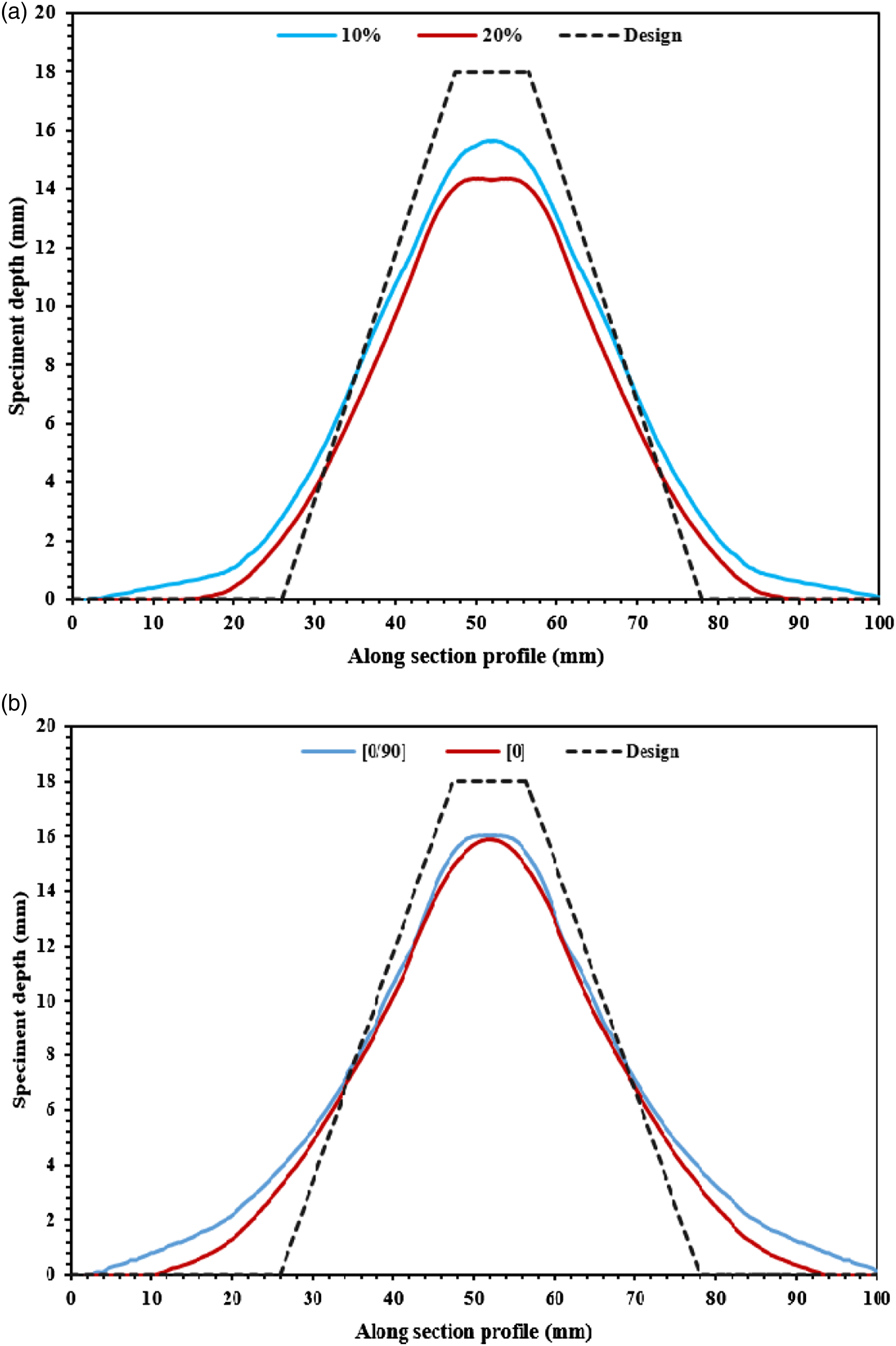
Feasibility of hole flanging of the PA6/GF composite sheet
In this study, in order to extend the use of the SPIF process in the forming of composite sheets, the feasibility of the hole flanging at the temperature of 165°C is investigated. For this purpose, the PA6/GF composite sheet with the volume fraction of 20% and the fiber orientation of [0] was considered and an initial hole with the diameter of 40 mm was drilled at the center of the sheet. As shown in Figure 21, the circular flange was successfully formed using a single-stage forming strategy. The hole flanging of the composite sheet at the temperature of 165°C with the volume fraction of 20% and the fiber orientation of [0]: (a) the fiber wrinkling, (b) a rupture at the edge of the sheet, and (c) a burr produced by drilling.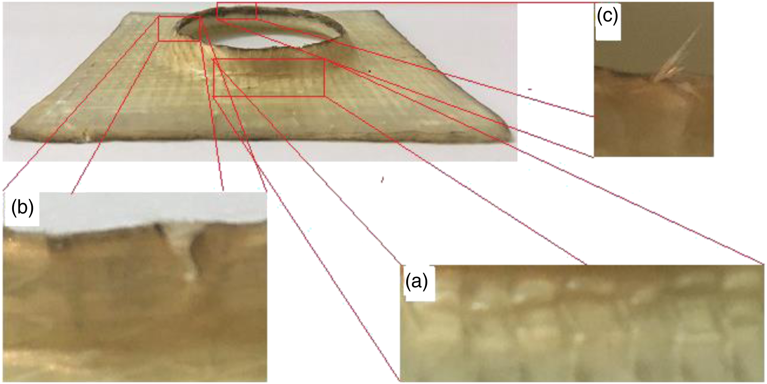
Defects like the fiber wrinkling can be observed around the area close to the edge of the backing plate. This can be attributed to either the relative sliding between fibers or the sliding between the layers, which induce a bigger shear angle between the fibers. As mentioned before, this phenomenon also occurred in the SPIF of the conical geometry. A crack at the free edge of the circular flange can be observed in Figure 21(b). While drilling the initial hole, burrs were created on the edge of the hole. As shown in Figure 21(c), the produced burrs can be considered as another defect.
Conclusions
In this study, the SPIF process of the conical geometry from both polymer (PA6) and composite (PA6/GF) sheets at elevated temperatures was experimentally investigated. For this purpose, an appropriate fixture with a ceramic infrared heating element was designed to assess the effect of the forming temperature and the volume fraction and orientation of fibers on the formability. Besides, the thickness distribution and the dimensional accuracy were also studied. Eventually, the feasibility of performing the hole flanging process on the composite sheet was examined. The following conclusions can be drawn: 1. The SPIF process of PA6 and PA6/GF sheets at room temperature is not possible. The conical geometry with the wall angle of 50° from the PA6 sheet can be formed by increasing the temperature to 115°C through the three-stage forming strategy. On the other hand, the conical geometry with the wall angle of 40° from the PA6/GF composite sheet can be formed by increasing the temperature to 165°C under a two-stage strategy. 2. By increasing the forming temperature and decreasing the fiber volume fraction, the formability of the PA6/GF composite sheet in the high-temperature SPIF increases. Additionally, the formability of the composite sheet with the arrangement of [0] is higher than the one with the arrangement of [0/90]. 3. Both the volume fraction and orientation of fibers have a noticeable effect on the maximum thinning and the draw-in of free edges of the composite sheet. The fiber orientation of [0/90] improves the thinning of the composite specimen. Moreover, the thinning in the composite specimen is improved by increasing the fiber volume fraction. The fiber volume fraction affects the dimensional accuracy since the thermal residual stress and the material shrinkage depend on this parameter. 4. A circular flange from the composite sheet was successfully formed by utilizing the high-temperature SPIF. The flanging process is limited by the crack initiation from the edge of the initial hole.
To get more insight into the observed experimental results, a FE analysis will be carried out as a future work. Using the FE analysis, it would be possible to study and identify dominant deformation mechanisms during the SPIF of composite sheets.
Footnotes
Declaration of conflicting interests
The author(s) declared no potential conflicts of interest with respect to the research, authorship, and/or publication of this article.
Funding
The author(s) received no financial support for the research, authorship, and/or publication of this article.