
Abstract
The single-point warm incremental forming (SPWIF) methodology significantly enhances the formability of composite materials, enabling precise and efficient shaping of complex geometries. This research investigates the impact of several design parameters such as fiber weight fraction (0%, 20%, 30% by weight), process temperature (80°C, 120°C, 180°C), step size (0.25 mm, 0.50 mm, 0.75 mm), and fiber orientation (0°, 22.5°, 45°) on the formability of glass fiber-reinforced polyamide six sheets. Employing the Taguchi design of experiments methodology, a systematic study was undertaken. The sample with a 20% fiber weight fraction, 80°C process temperature, 0.50 mm step size, and 0° fiber orientation showed the greatest forming depth at 5.5 mm. Additionally, the study highlighted the predominant influence of fiber weight fraction on forming depth, attributing a significant contribution percentage of 58.75% to forming depth. Moreover, a numerical analysis, encompassing the homogenization of the composite sheet and simulation of the SPWIF process, was conducted. The findings revealed a consistent trend for both experimental and numerical results. For depth analysis, the thickness distribution was simulated, aligning with the observed experimental trends. This demonstrates the reliability of the numerical results. This research not only provides a detailed analysis of the SPWIF process in shaping composite sheets but also serves as a valuable resource for scholars engaging in numerical analyses within this domain.
Keywords
Introduction
The distinct characteristics of fiber-reinforced polymer (FRP) composites include elevated specific strength, stiffness, fatigue strength, and energy absorption capacity. These are coupled with outstanding corrosion resistance and reduced installation, operational, and maintenance expenses, drawing significant attention. Consequently, these attributes make FRP composites highly suitable for replacing conventional materials in diverse engineering applications. 1 Typically, FRP composites can be classified into thermoplastic and thermoset composites, with a preference for thermoplastic composites owing to their recyclability, heightened toughness, and flexibility, particularly in structures subjected to static and fatigue loading conditions. 2 The manufacturing processes for thermoplastic composites encompass thermoforming, tape winding, compression molding, autoclave processing, diaphragm forming, and blow molding, selected based on factors such as production rate, initial cost, material properties, and the final size and shape of the specimen. 3
The Incremental Sheet Forming (ISF) process stands out as a versatile technique for rapid prototyping, allowing the conversion of a flat sheet into a desired three-dimensional form without requiring specific dies and punches. 4 Among the variants of ISF, Single Point Incremental Forming (SPIF) is particularly popular due to its cost-effectiveness and flexibility, despite limitations such as prolonged forming times, high thinning, and low dimensional accuracy. 5 Recent investigations have shown that using SPIF for forming polymer sheets, with pivotal process parameters like vertical pitch and tool diameter exerting significant influence on the formability of such sheets. 6 Research endeavors have examined the impact of parameters such as vertical pitch and tool rotation on SPIF of polymer sheets. They revealed enhanced formability with increased vertical pitch, though it is constrained by the occurrence of wrinkling. 7 For instance, Centeno et al. explored the influence of process parameters on the surface quality and forming temperature in SPIF of various polymer sheets, including glass fiber-reinforced polyamide 6 (PA6). Their findings underscored the significant effect of spindle speed on forming temperature. 8 This observation aligns with the study by Zhang et al., which delved into the influence of glass fiber on the hydrothermal aging of PA6, noting that the presence of glass fibers hindered water absorption in PA6. 9 Unnikrishnan et al. advocated for the utilization of recycled glass fibers as reinforcing fillers in PA6 polymers to enhance mechanical and thermal properties. 10 The reinforcement impact of glass fiber on PA6 composites was scrutinized by Luo et al., who emphasized the challenge of establishing a robust interfacial interaction between glass fiber and the PA6 matrix due to intrinsic property disparities. 11 Ksouri et al. conducted a comprehensive investigation into the long-term aging of PA6 reinforced with glass fibers, elucidating the influence of glass fibers on the physicochemical and mechanical properties of the composite. 12 The exploration of forming composite sheets at both room and elevated temperatures using conventional processes with dedicated dies has been a primary focus of research. Hodžić et al. conducted an experimental study, revealing the forming limit diagram of recycled polymeric matrix composites and demonstrating their ability to withstand stress states ranging from pure shear to biaxial tension at room temperature. 13 Fazio et al. employed microscale Finite Element (FE) modeling to investigate the stamping process of a cone-shaped part from a woven composite with a thermoplastic matrix, predicting thermoplastic prepreg tow properties for employment in a mesoscale FE model . 14 Isogawa et al. studied the effects of forming temperature and blank holder pressure on the formability and geometrical accuracy of PA66 matrix composite sheets reinforced by carbon woven fabric in the deep-drawing process, highlighting the necessity of optimizing these parameters to prevent wrinkling . 15 Additionally, Ahn et al. conducted a numerical study on various parameters in the thermohydroforming process of multilayer-reinforced composite blanks, demonstrating that modified hydroforming processes could reduce wrinkling density and height. 16
Prior studies recommend exploring of SPWIF as an alternative to conventional methods for production of polymer matrix composites. This research specifically focuses on applying SPWIF to a truncated square pyramid using PA6 sheets. It also involves glass fiber-reinforced polyamide matrix composite sheets (PA6/GF). Although PA6/GF composites are widely used in the automotive and aerospace industries, their formability has not been thoroughly examined. Diverging from previous research, this study introduces a laminated composite with a new forming design, namely a truncated square pyramid. The study employed both hot and cold pressing methods in sheet formation process. For a detailed analysis, the study incorporated two finite element steps to model the composite sheets and simulate the SPWIF process. An investigation followed that studied the impact of various design parameters, namely fiber weight fraction, process temperature, step size, and fiber orientation, on the formability of PA6/GF sheets. Using the Taguchi design of experiments methodology, the study systematically examined these parameters. Additionally, the study conducted a numerical analysis, which included the homogenizing of the composite sheet and simulating of the SPWIF process, to gain a comprehensive understanding of the problem. Finally, the study assessed thickness distribution, force analysis, dimensional accuracy, and maximum stress on a sample during the SPWIF process, focusing on the sample with the highest forming depth.
Experimental work
Design of experiment
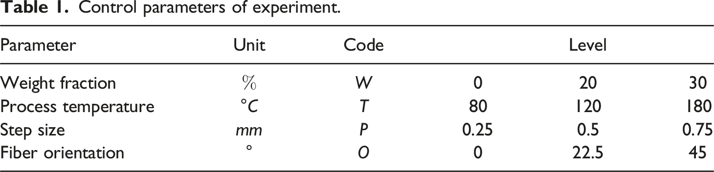
Control parameters of experiment.
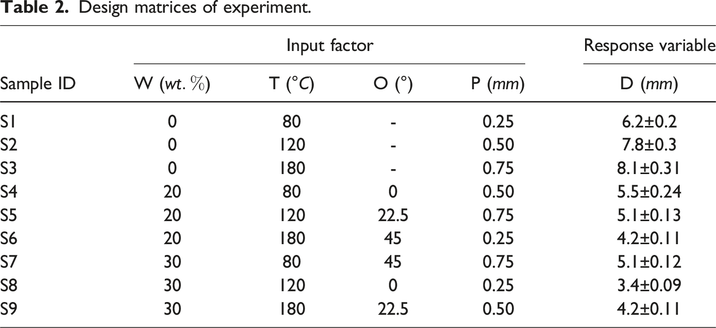
Design matrices of experiment.
Manufacturing methodologies
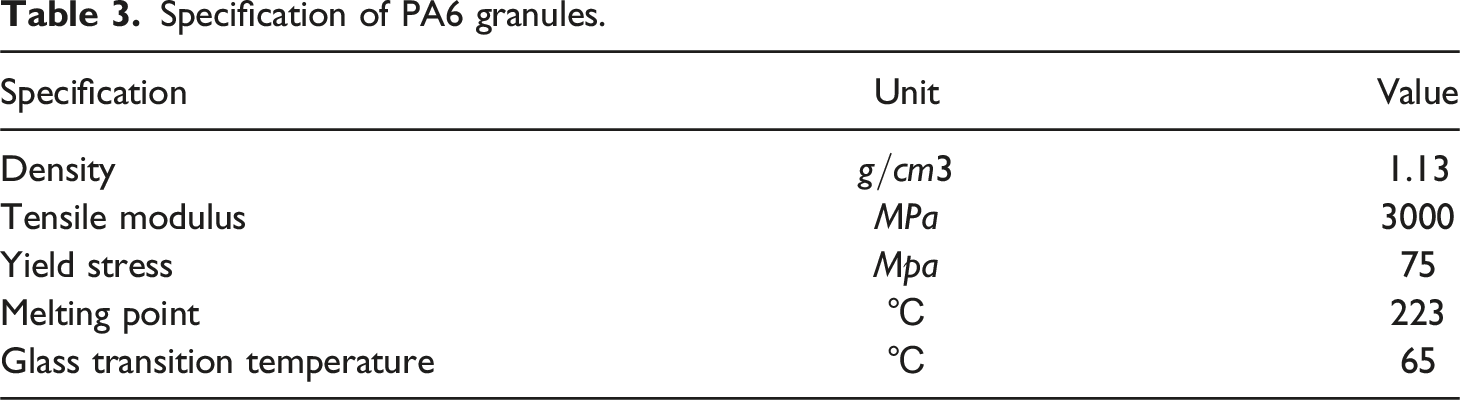
Specification of PA6 granules.
The production of PA6 sheets, as shown in Figure 1, followed a systematic process to ensure optimal material characteristics. Initially, 45 g of PA6 pellets were dried for a 20 h in an oven set to 70°C to remove residual moisture. These dried pellets were then carefully placed in a specialized mold measuring 130 × 130 mm2, which allows for the production of sheets with thicknesses of 0.3, 0.5, and 2 mm. This assembly was then placed in a hot pressing machine. It was exposed to temperatures of 260°C and a pressure of 30 bar for 5 min, facilitating material consolidation. Afterwards, the mold was moved to a cold pressing apparatus that operates at 90°C and 15 bar for 15 min, further enhancing material properties. Graph showing the temperature and pressure profiles during the hot and cold pressing processes of PA6.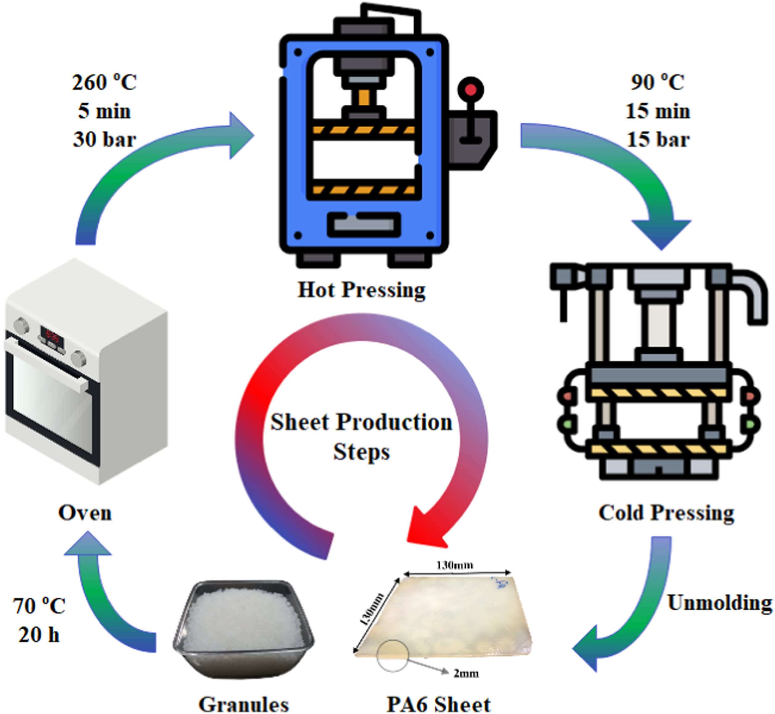
Hot and cold pressing parameters.
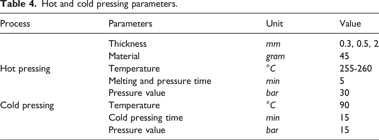
In the experimental design, baseline samples used un-reinforced PA6 sheets with a standardized thickness of 2 mm. To adjust the weight fraction in the composite, a specific stacking sequence shown in Figure 2(a)–(b) was employed. Specifically, to achieve a glass fabric weight fraction of 30%, four 0.3 mm thick PA6 sheets were alternated with three layers of glass fabrics in a mold. Following this arrangement, the materials underwent a series of thermal treatments such as drying, hot pressing, and cold pressing as detailed in Figure 1. For a 20% weight fraction, the composition was adjusted to three PA6 sheets of 0.5 mm thickness and two layers of glass fabrics. Additionally, the orientation angles were deliberately altered. The foundational fabric was set at zero degrees, and the subsequent layers' angles were systematically varied, as depicted in Figure 2(c)–(d). Furthermore, in three-layer configurations, the topmost fabric was aligned at a zero orientation angle for consistency in comparative analysis. In total, six laminates coded as (a) Stacking sequence of PA6 sheets and glass fabric with a volume fraction of 30 wt%, (b) stacking sequence with a volume fraction of 20 wt%, (c) fiber orientation angle of 45°, and (d) fiber orientation angle of 0°.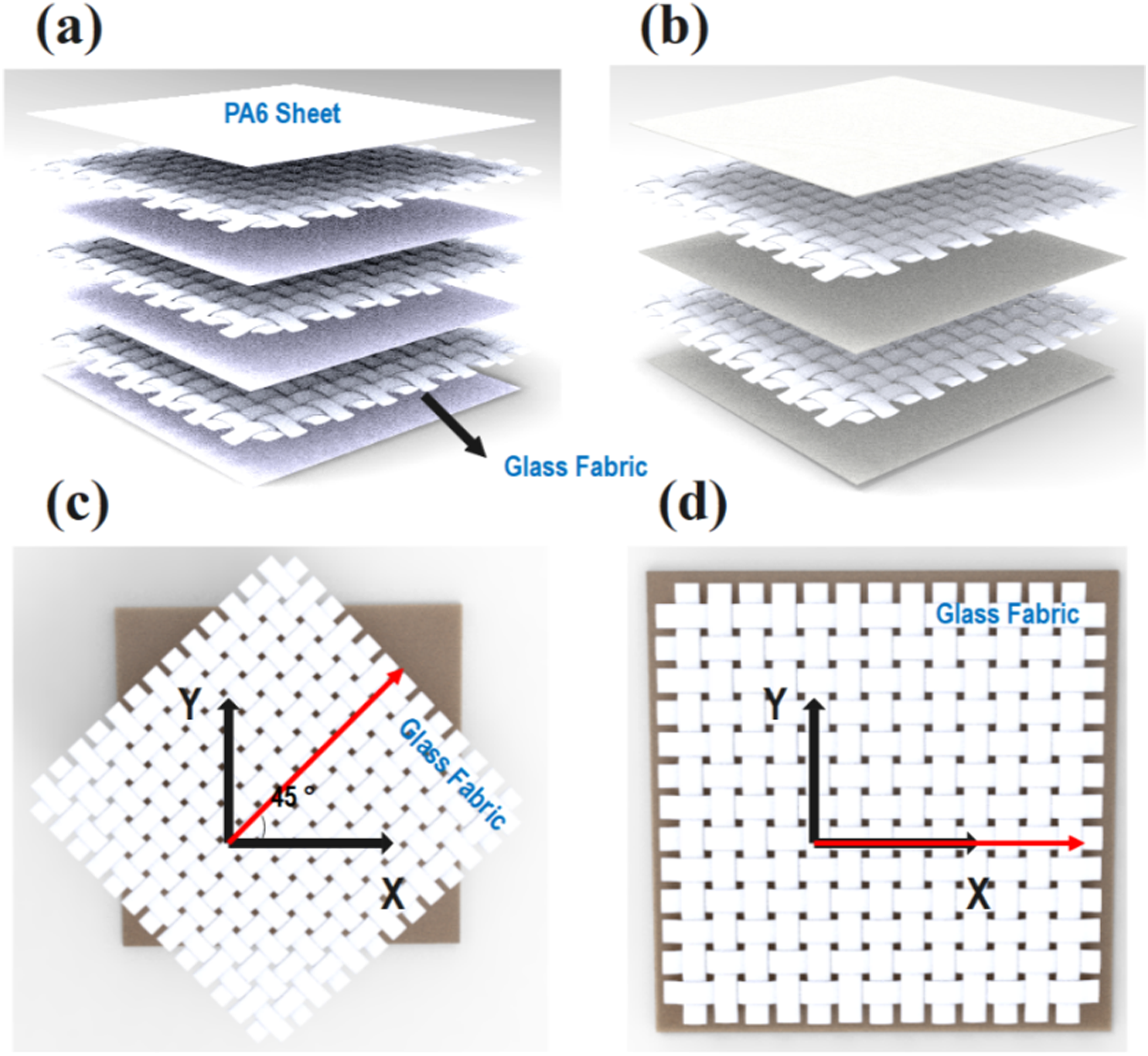
This study adopted a methodology similar to those referenced in sources.18,19 Figure 3(a) illustrates equipment used for the SPWIF process, which varied the temperature and followed distinct tool path increments to shape composite sheets. This equipment was precisely configured on a 3-axis CNC milling machine. A K-type thermocouple was used to monitor the temperature of the composite. Figure 3(b) shows a detailed schematic of the involved components. The chamber was heated using a ceramic infrared heating element with a peak power of 700W and a maximum temperature of 900°C. Furthermore, to reduce thermal dissipation, the chamber was insulated with an aluminum barrier and glass wool blanket. Figure 3(c) provides a graphical depiction of the tool’s trajectory and the resultant component. The semi-spherical forming tool had a diameter of 10 mm, and a consistent feed rate of 1200 mm/min was maintained during the operation. Figure 3(d) outlines sheets' structural configuration during the SPWIF procedure. To maintain fabric alignment during SPWIF, a 0.5 mm thick stainless steel (ss316 L) backup sheet was strategically placed atop the composite. Additionally, a steel sheet matching the uppermost layer was used to evenly distribute heat across the composite. A 13-micron thick Teflon layer was cleverly placed between the steel sheet and the composite to prevent unwanted adhesion. It should be noted that no lubricant was used during the SPWIF process. (a) Actual photograph of the SPWIF setup (b) detailed schematic of the SPWIF setup (c) diagram illustrating the principles of SPWIF, and (d) schematic showing the workpiece assembly and clamping mechanism.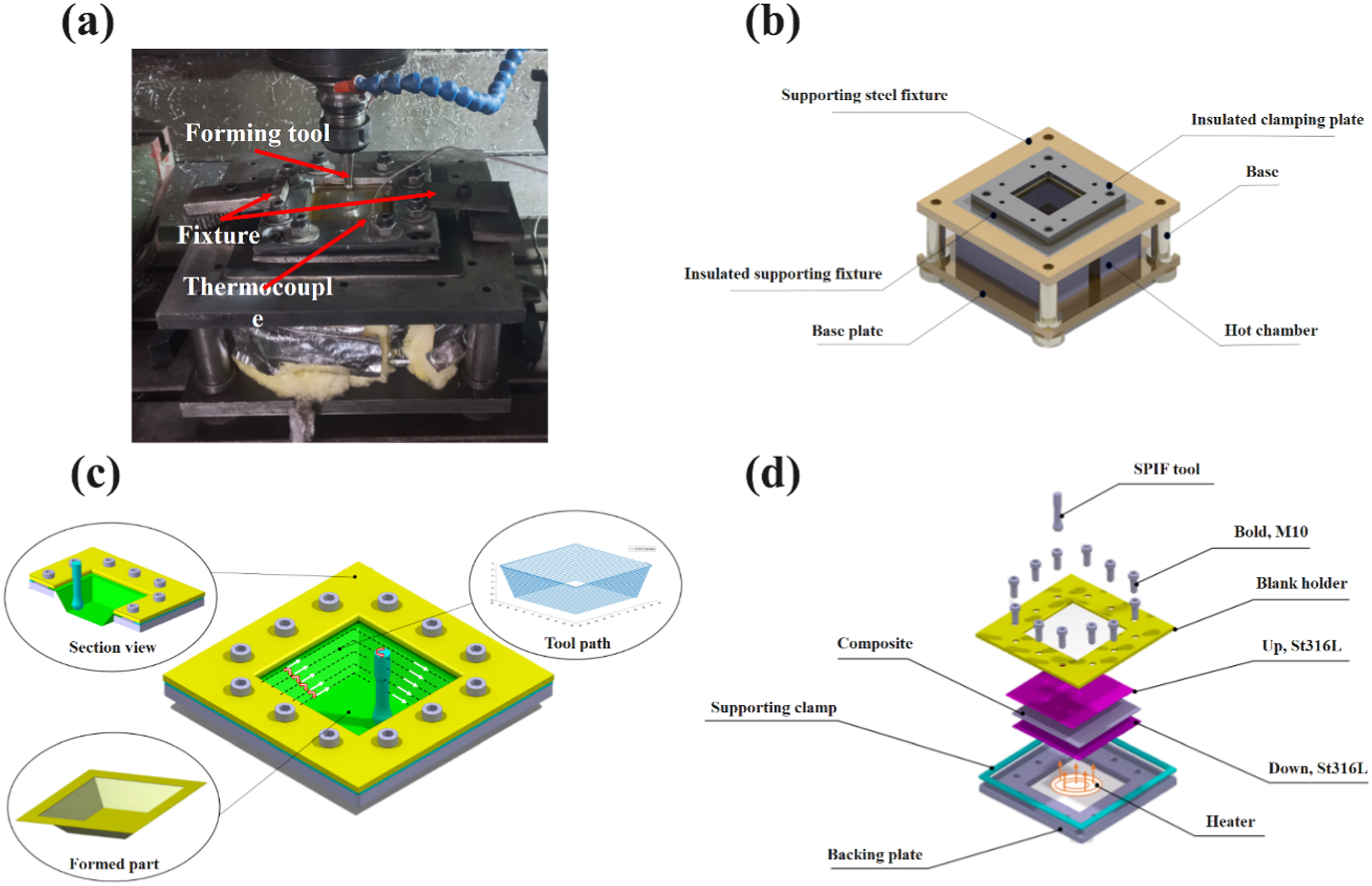
Characterization methodologies
To determine the tensile characteristics of specimens under controlled temperatures, two established standards were used: ASTM E8/E8M-22 for composite materials and ASTM D3039 for non-reinforced PA6, using the SANTAM STM 20 testing apparatus. Figure 4 shows a CAD illustration and manufactured samples, illustrating the design of the specimens prepared for the tensile testing. CAD designs and actual manufactured samples prepared for tensile testing: (a) composite material, (b) non-reinforced PA6.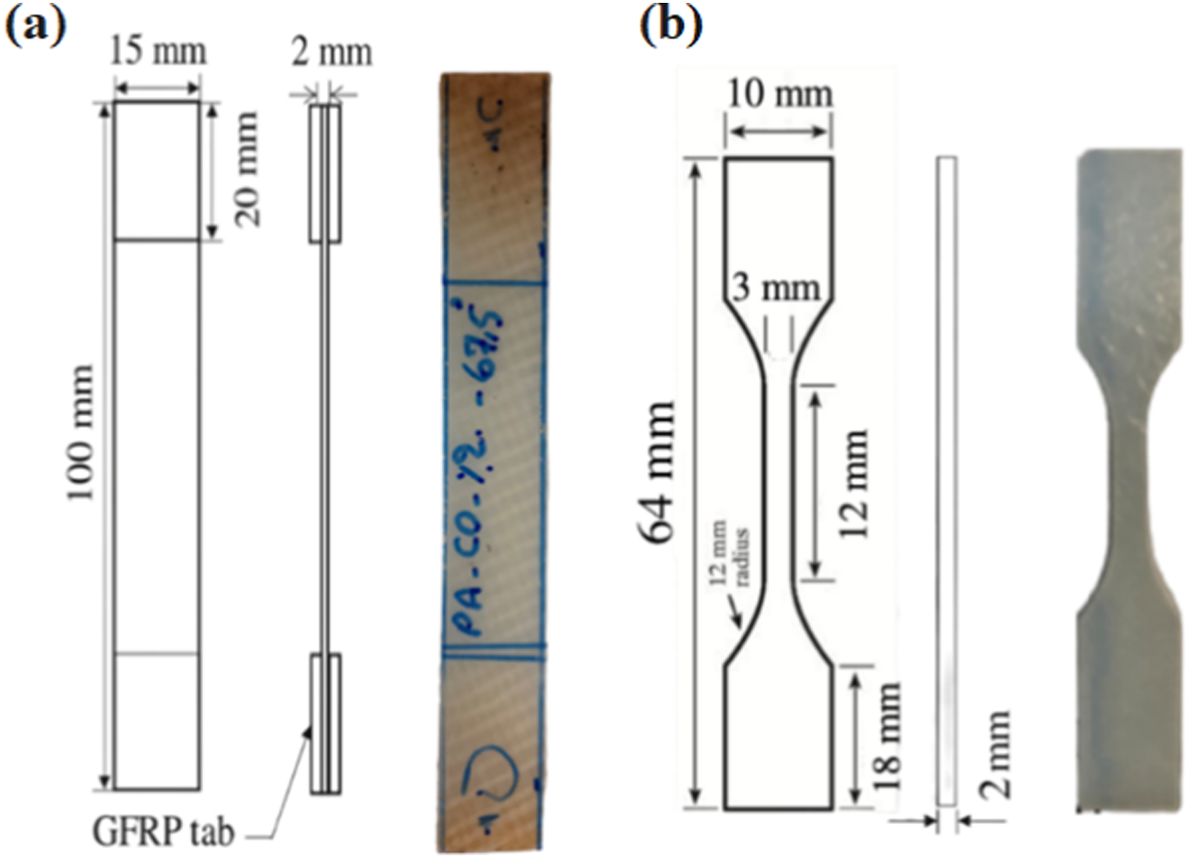
To investigate the morphology of composite, specimens with dimensions of 1
Numerical Modeling
The main objective of this study is to investigate the forming behavior of PA6 composite sheets through SPWIF technique under different weight fractions, process temperature, fiber orientation, and step sizes using Taguchi method. To enable a comprehensive simulation of the SPWIF process under ABAQUS Software 2022, initial engineering constants of the composite Representative Volume Element (RVE) were determined using the Ansys Software 2022. The modeling of woven fabric reinforced laminates consists of three scales: micromechanical modeling of yarn, mesomechanical modeling of woven fabric reinforced composite, and macromechanical modeling of woven fabric reinforced laminate. This multi-scale approach allows for a comprehensive understanding of the behavior and properties of the laminates. Micromechanical modeling focuses on the individual yarns and their mechanical properties, while mesomechanical modeling considers the interactions between yarns within the fabric. Subsequently, the composite RVEs were used to determine material properties throughout the SPWIF simulation. Figure 5 delineates the sequential flowchart illustrating the steps undertaken in this research endeavor. Flowchart of various steps involved in this study.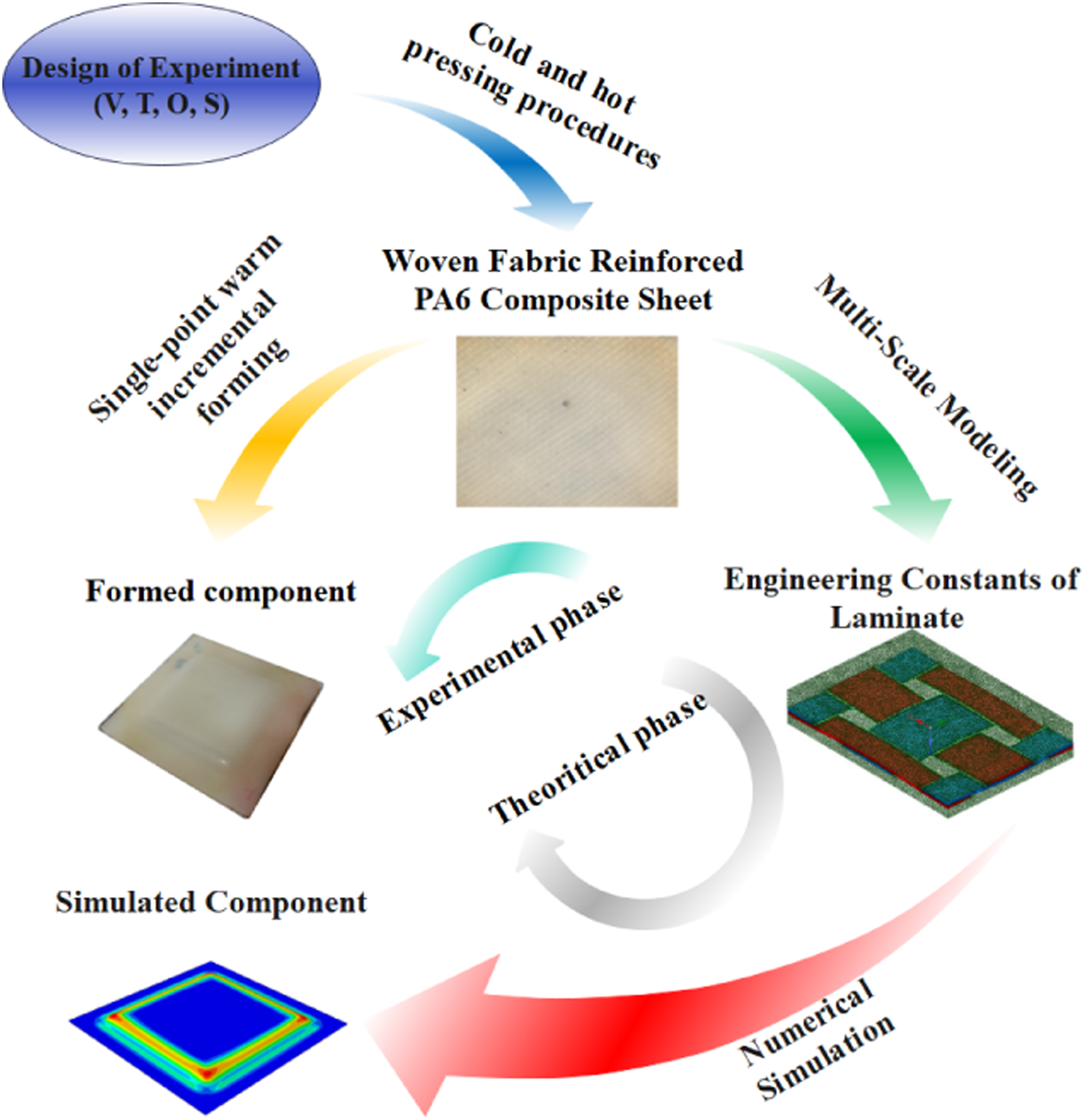
Simulation of Composite Sheet
Micromechanical Modeling of Yarn
Yarn consists of fibers that, in conjunction with resin, can constitute a unidirectional composite .
20
To achieve this, it is essential to determine the fiber volume fraction and understand the mechanical and physical properties of both the fiber and resin. Using Ansys Finite Element Software, we modeled the yarn’s microscale cross-section by considering a RVE in three dimensions. This software allows for the specification of geometric parameters, characterization of fiber and resin attributes, determination of fiber volume fraction, and geometric meshing to compute the equivalent properties of the composite. In Figure 6, the 3D geometry and meshing of the RVE are illustrated, which features a fiber diameter of 14.6 μm and a fiber volume fraction of 0.8 in the yarn. Moreover, it is crucial to emphasize the role of temperature in this process. The simulation was conducted across three distinct temperature conditions, reflecting the temperature-dependent variability in the characteristics of the resin, while the properties of the fiber remain relatively constant. Cross-sectional view of the micromechanical yarn model simulated in ANSYS software.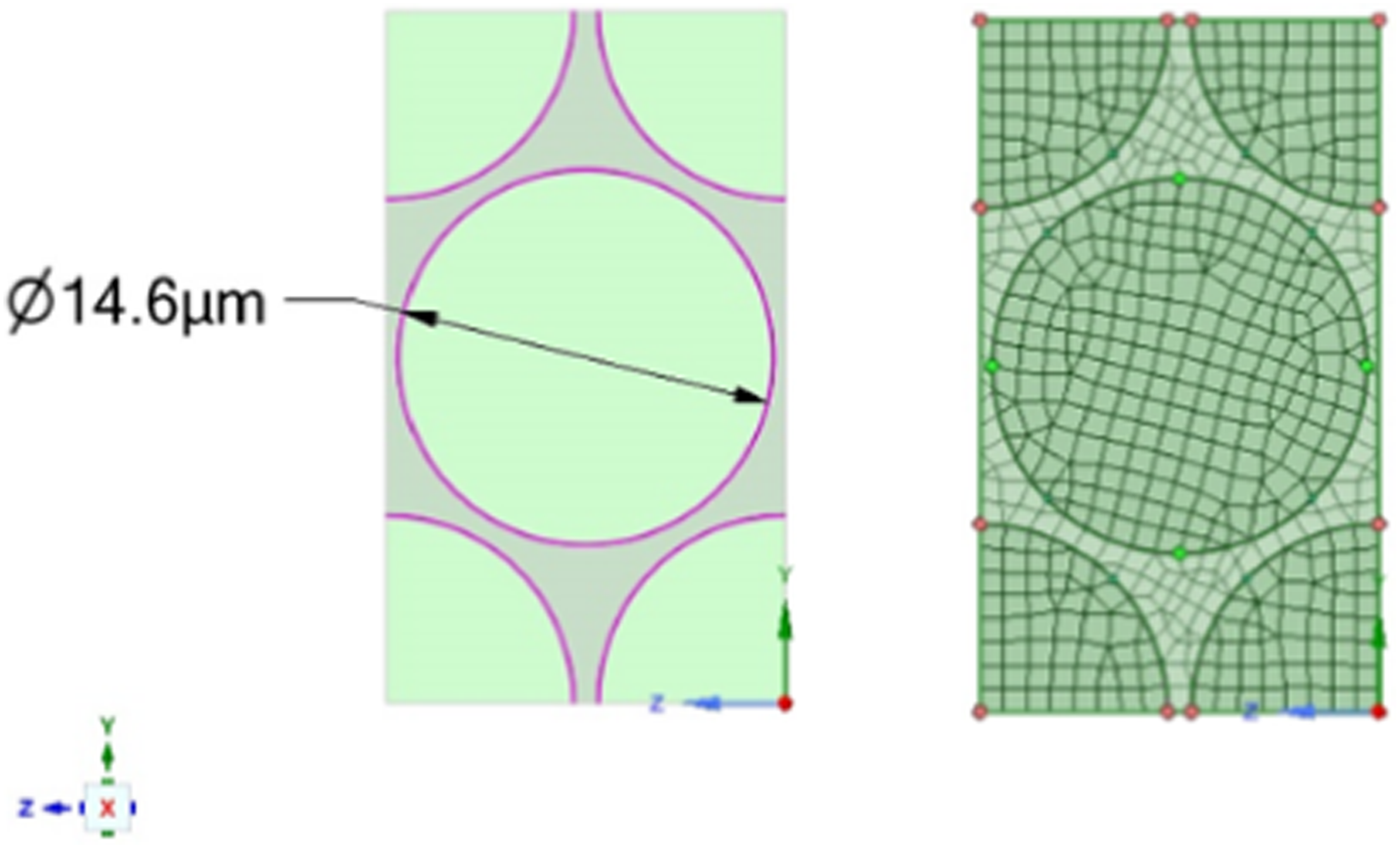
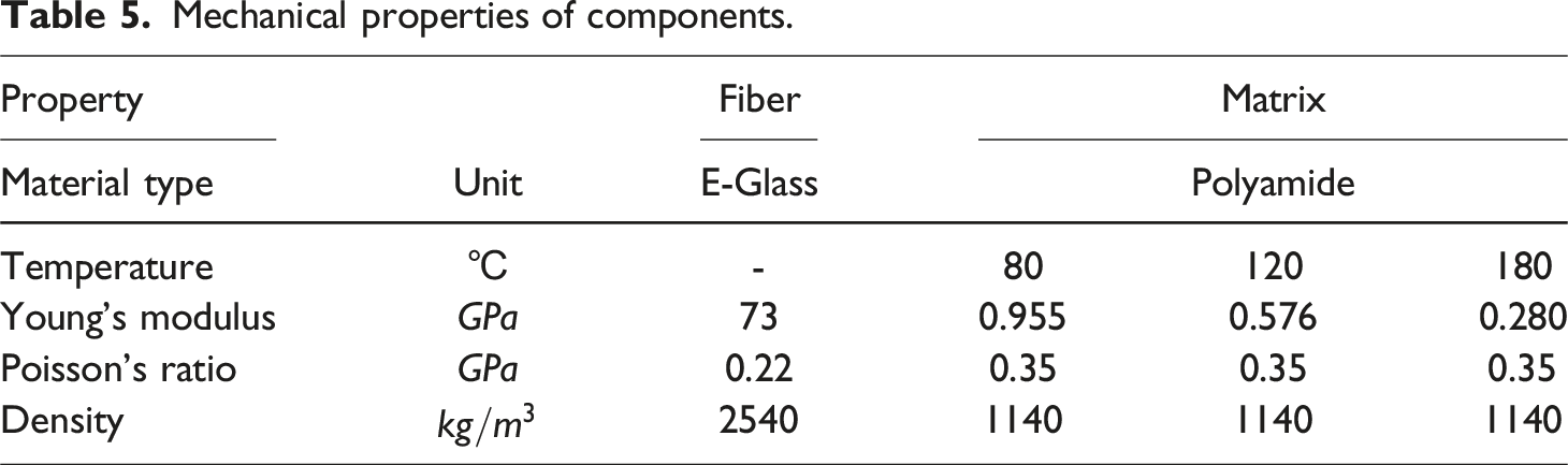
Mechanical properties of components.
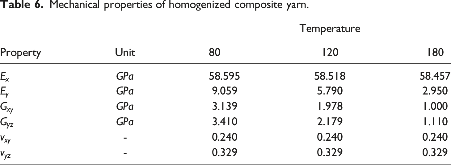
Mechanical properties of homogenized composite yarn.
Mesomechanical modeling of woven fabric reinforced composite
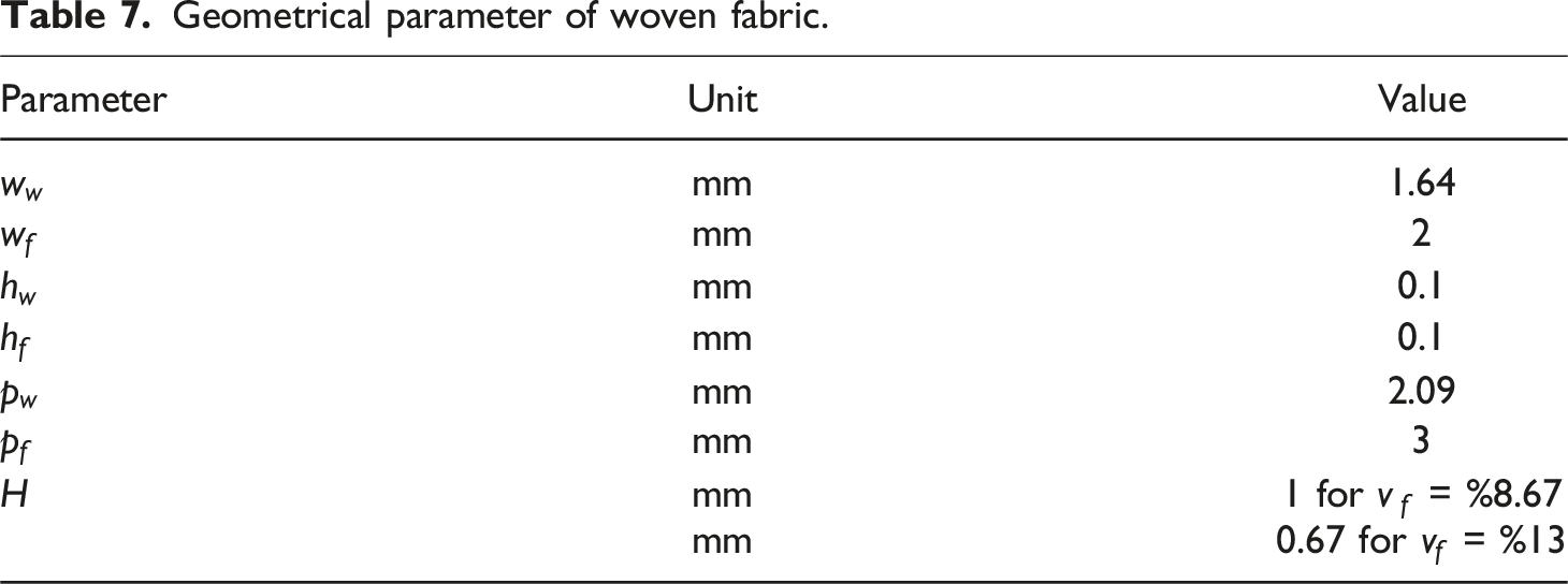
Geometrical parameter of woven fabric.
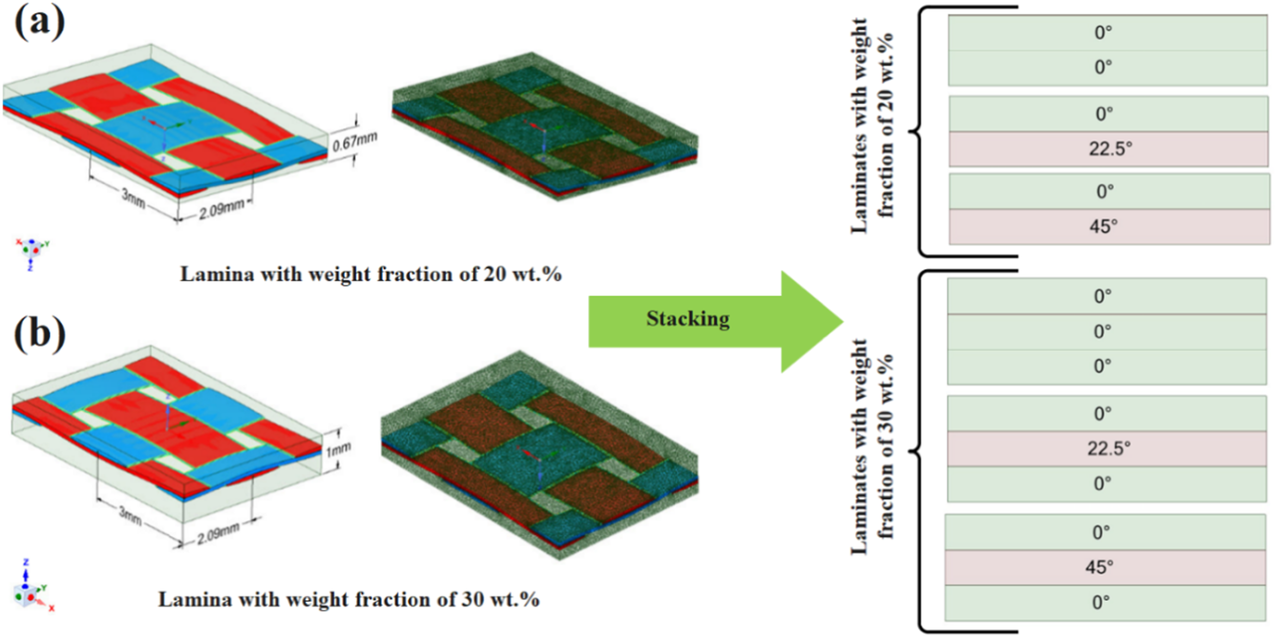
Mesomechanical model of lamina and stacking sequence for (a) 20 wt% and (b) 30 wt% simulated in ANSYS software.
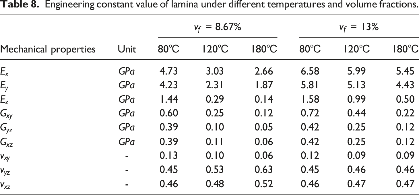
Engineering constant value of lamina under different temperatures and volume fractions.
This investigation examined six categories of laminated composites, each characterized by distinct angles. The initial three categories featured a volume fraction of 8.67%, while the subsequent three categories had a volume fraction of 13%. The former consists of two composite layers, while the latter includes three composite layers. Figure 7 depicts a schematic representation of these six configurations. Using the mechanical properties derived from the plain woven composite in the preceding phase, each of these six groups was modeled in ABAQUS Software for a detailed subsequent analysis.
Simulation of SPWIF process
Before initiating the SPWIF simulation using the ABAQUS software, laminates were meticulously assembled as outlined in the previous section. To start the SPWIF simulation, we considered five geometries for the components. For the backing plate, we created a square with measuring 170 3D plot of forming tool path with various tool step sizes, (a) 0.25 mm/rev (b) 0.50 mm/rev (c) 0.75 mm/rev, and (d) simulated components in Abaqus Software.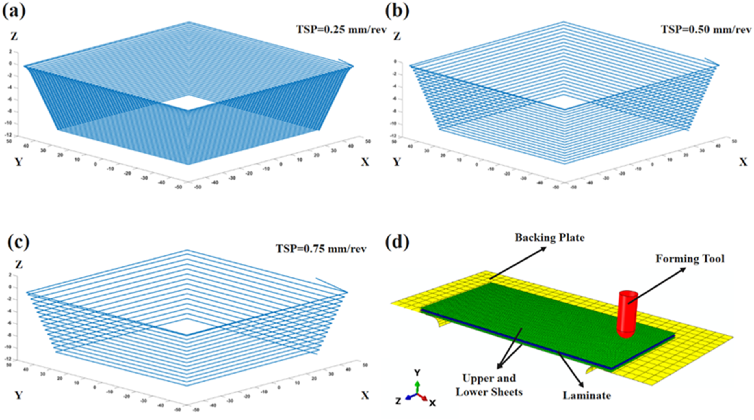
For the mesh size independency analysis, we employed various mesh sizes for the laminates, as depicted in Figure 9. Ultimately, we settled on a final mesh size of 1-mm, resulting in a total of 17,000 elements. The selection of the element size was conducted carefully, considering the computational cost associated with simulations. It is important to note that the computational cost increases exponentially as the element size decreases. Our objective was to identify an optimal element size that would yield an acceptable convergence error for the software output. Mesh independency analysis of the SPWIF process.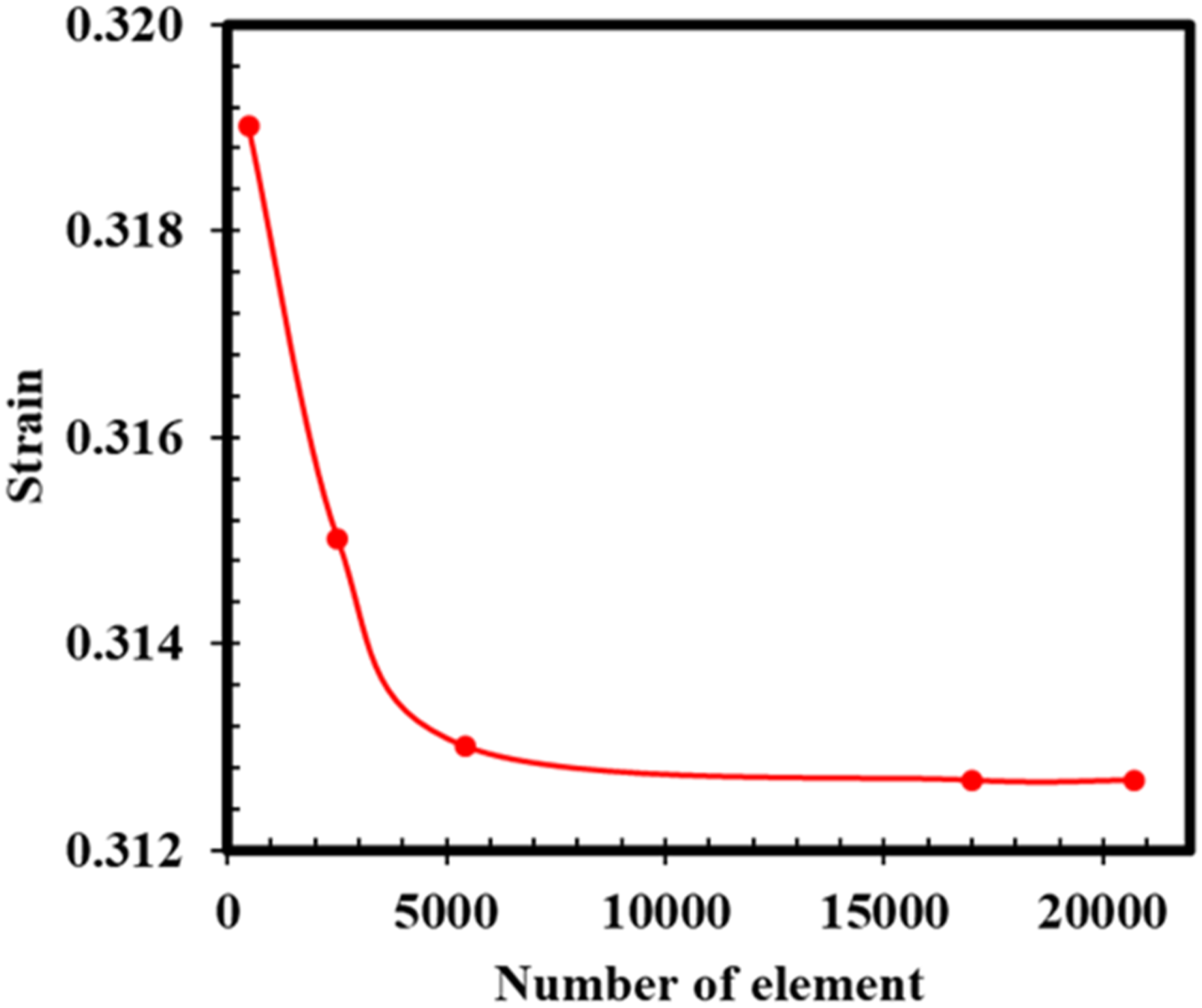
Results and discussions
Tensile behavior of components
The stress-strain characteristics of the various components used in this study are illustrated in Figure 10. Examination of Figure 10(a) revealed that the stainless steel (ss316 L) sheet nearly uniform tensile behavior exhibited across different angles. Consequently, the forming process appeared to be unaffected by variations in the forming behavior of the ss316 L sheet in diverse regions. Essentially, the ss316 L sheet can be characterized as anisotropic material. Upon examining the PA6 sheet, as shown in Figure 10(b), a clear trend emerged where an increase in temperature from 80 to 120°C correlated with a reduction in Young’s modulus, maximum stress, and strain at breakage. This observed effect is attributed to the increased mobility of polymeric chains facilitated by elevated temperatures, leading to a decrease in resistance under these higher temperature conditions.22–25 Stress-strain curve of stain of (a) ss316 L sheet, (b) PA6 sheet, (c) laminates with 20 wt% of glass fiber, and (d) laminates with 30 wt% of glass fiber.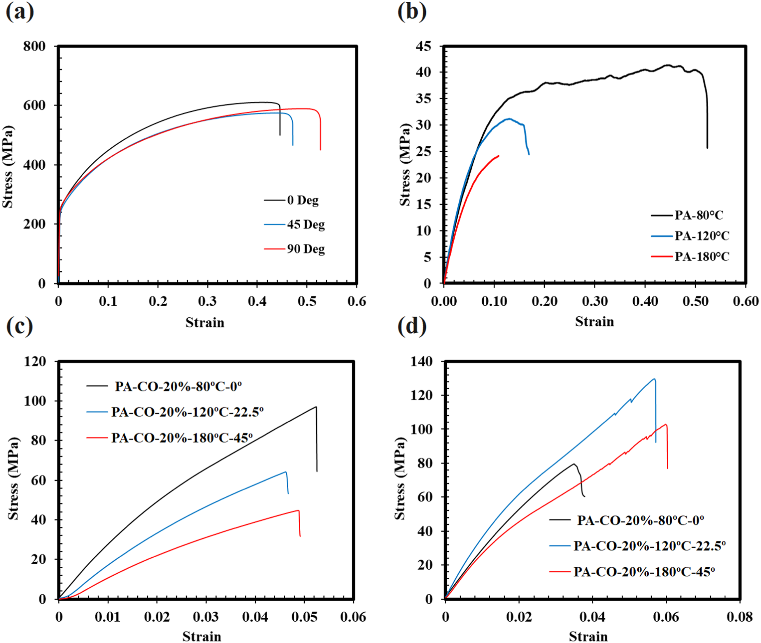
The behavior of glass fiber-reinforced PA6 composite sheets was multifaceted. Specifically, four influential factors including fiber weight fraction, process temperature, and fiber orientation affect the tensile behavior of these PA6 composite sheets. Generally, an enhancement in tensile behavior was observed when the fiber weight fraction was increased, the process temperature was decreased, and the fiber orientation was set to zero degrees. Examining samples S4, S5, and S6, as illustrated in Figure 10(c), where the fiber weight fraction remained constant at 20 wt%, while the temperature (ranging from 80 to 120°C) and orientation (varying from 0 to 45°) were manipulated, it was observed that elevating the temperature and increasing the orientation angle lead to a reduction in tensile modulus, tensile maximum stress, and tensile strain at breakage. Conversely, considering samples S7, S8, and S9 in Figure 10(d), a distinct pattern emerged. In S7, with a fiber weight fraction of 30 wt%, process temperature of 80°C, and fiber orientation of 45°, maintaining the fiber weight fraction while altering the process temperature to 120°C and the fiber orientation to 0° in S8 revealed that an increase in temperature might result in a decline in tensile behavior, but a reduction in orientation angle dominated, ultimately leading to an improvement in tensile behavior. A comparison between S7 and S9 indicates that the increase in temperature predominates over the reduction in orientation, resulted in the deterioration of the tensile behavior of glass fiber-reinforced PA6 composite sheets. Notably, an increase in the fiber weight fraction correlated with an improvement in the tensile behavior of these PA6 composite sheets.
Morphological properties of PA6 sheets and its composites
The morphological characteristics of the PA6 and glass fiber-reinforced laminate containing 20 wt% are illustrated in Figure 11, as discerned from scanning electron microscopy (SEM) images. The observations revealed a well-formed structure of PA6 achieved through both hot and cold pressing processes (Figure 11(a)). Turning attention to the glass fiber-reinforced laminate with a 20 wt% composition, consistent behavior of the matrix was observed during both hot and cold pressing processes (Figure 11(b)). Notably, the presence of two glass woven fabrics resulted in the stacking of two laminae in sequence, establishes three distinct regions. The uniformity in matrix morphology across all three regions indicated that during the hot pressing phase, PA6 granules underwent complete melting, subsequently forming a glass fiber-reinforced laminate after the cold pressing step (Figure 11(c)). Finally, Figure 11(d) depicts a lamina comprising a layer of PA6 reinforced with glass fiber, where the orientation of the glass fibers remained unchanged throughout the hot and cold pressing steps. This consistency implies a uniform application of pressure during the sheet formation process. SEM image of (a) PA6 sheet, (b) glass fiber reinforced laminate with 20 wt%, (c) lamina arrangement in laminate with 20 wt% of glass fiber, and (d) glass fiber reinforced lamina.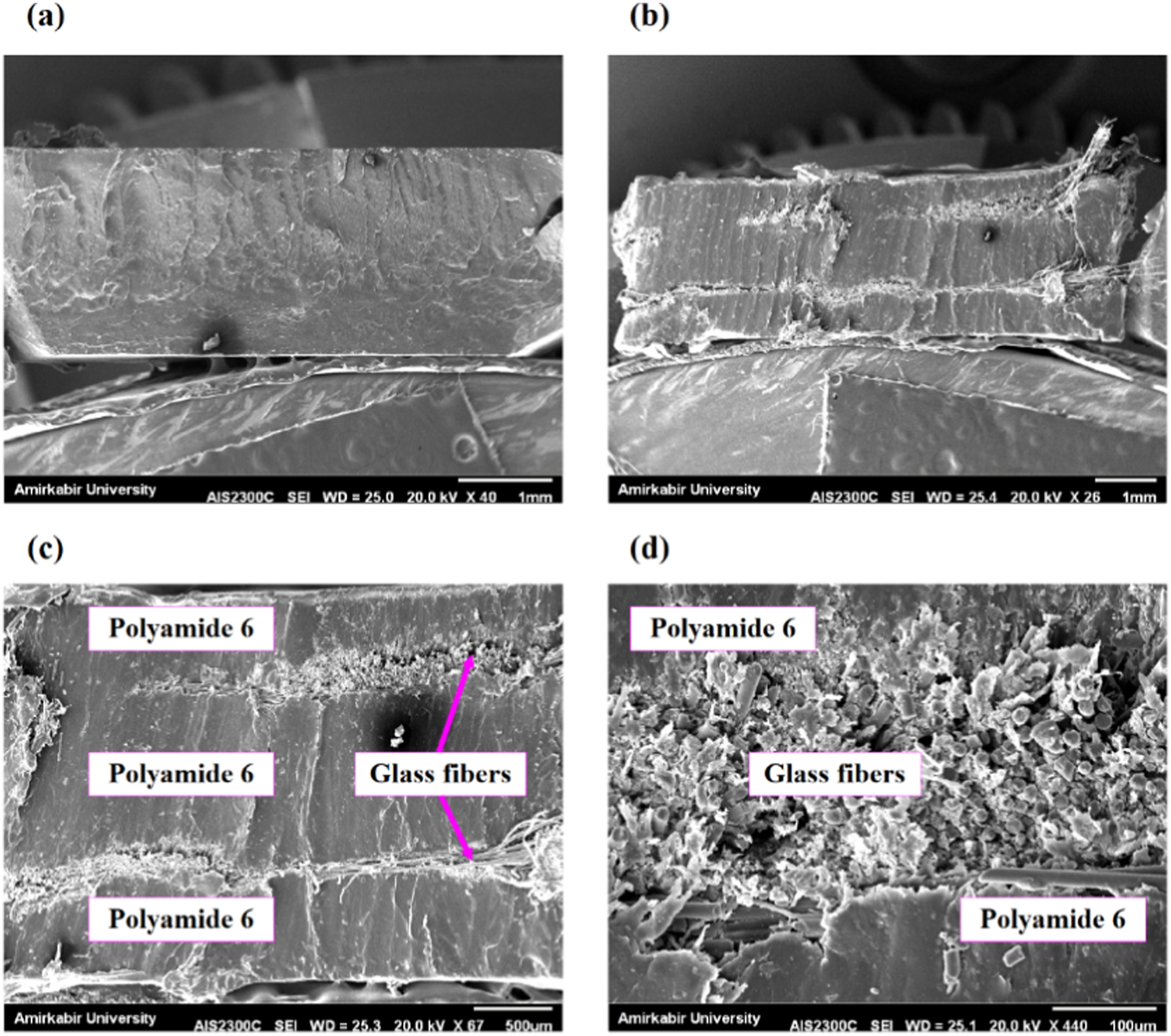
Statistical effect of control parameters
ANOVA analysis of main parameters.
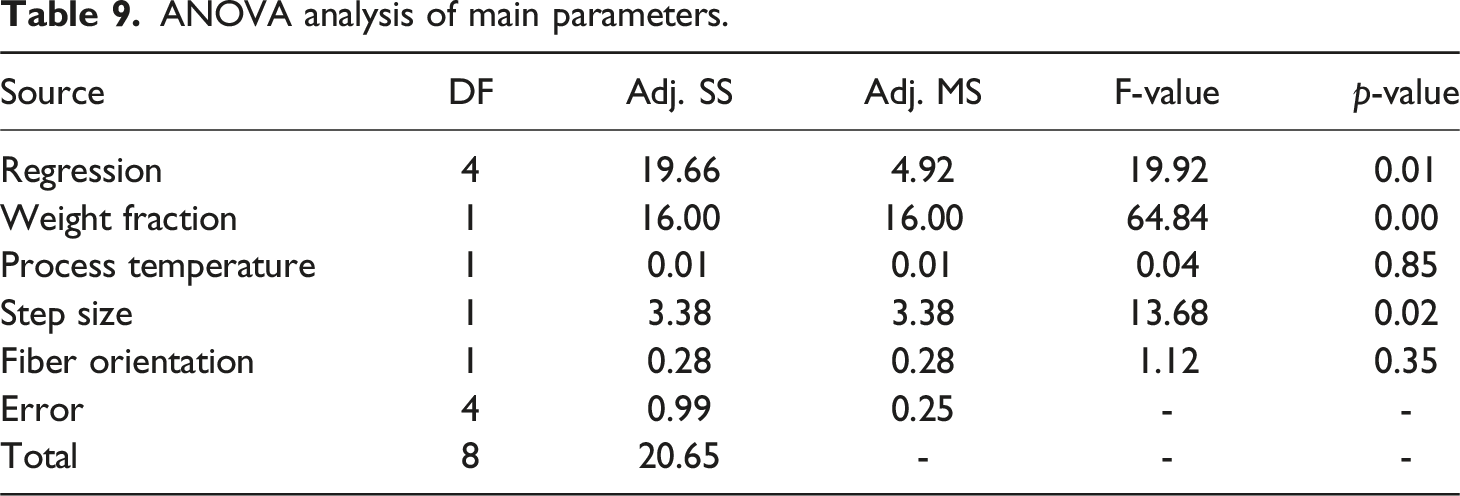
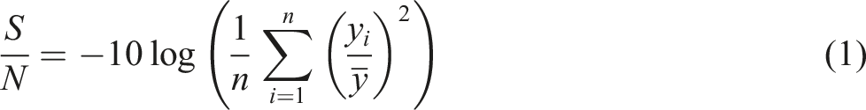
Furthermore, Figure 12 displays both the SN ratio diagram and the percentage contribution of each factor. In Figure 12(a), an increase in weight fraction correlated with a reduction in forming depth, whereas a higher step size led to an increased forming depth. Additionally, the impact of temperature on forming depth initially decreased and then rose. Concerning fiber orientation, a peak was evident at the mid-point. Analyzing the factor contributions in Figure 12(b), it is clear that the fiber weight fraction held the highest contribution at 58.75%, while the process temperature exhibited the lowest contribution at 3.13% to the variation in forming depth. It is important to note that these results are statistical in nature, and their interpretation should be approached with caution in the absence of a direct correlation with the underlying physics of the problem. (a) Parametric effect of factors and (b) contribution of factors.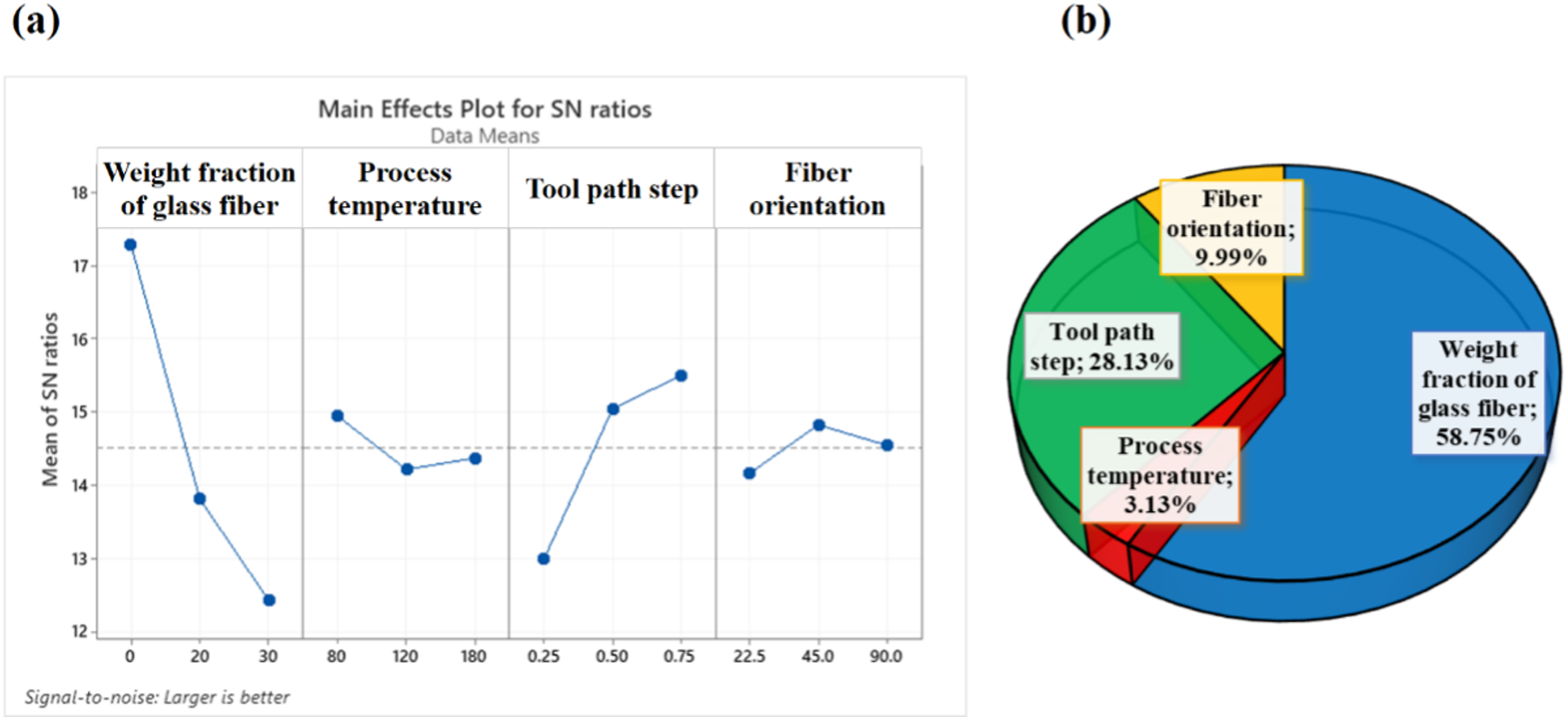
Figure 13 presents the forming depth of samples produced in this study. Notably, an increase in both the temperature and step size of PA6 composite sheets during SPWIF process correlated with an increase in forming depth, from 6.2 mm to 8.1 mm. This augmentation can be attributed to the heightened mobility of polymeric chains, which was facilitated by elevated temperatures, thereby enhancing sample formation. Simultaneously, an increased step size resulted in greater force applied to the sample during the SPWIF process, contributing to the observed increase in forming depth. In the subsequent three samples incorporating 20 wt% of glass fiber, temperature was escalated while the step size increased and then decreased, and fiber orientation diminished. This intricate interplay of factors led to a reduction in forming depth from 5.5 mm to 4.2 mm. Moving to the final three samples with 30 wt% of glass fiber, the forming depth initially decreased from 5.1 mm to 3.4 mm, then increased to 4.2 mm, showcasing a dynamic response influenced by the combined effects of temperature, step size, and fiber orientation. Forming depth of various samples.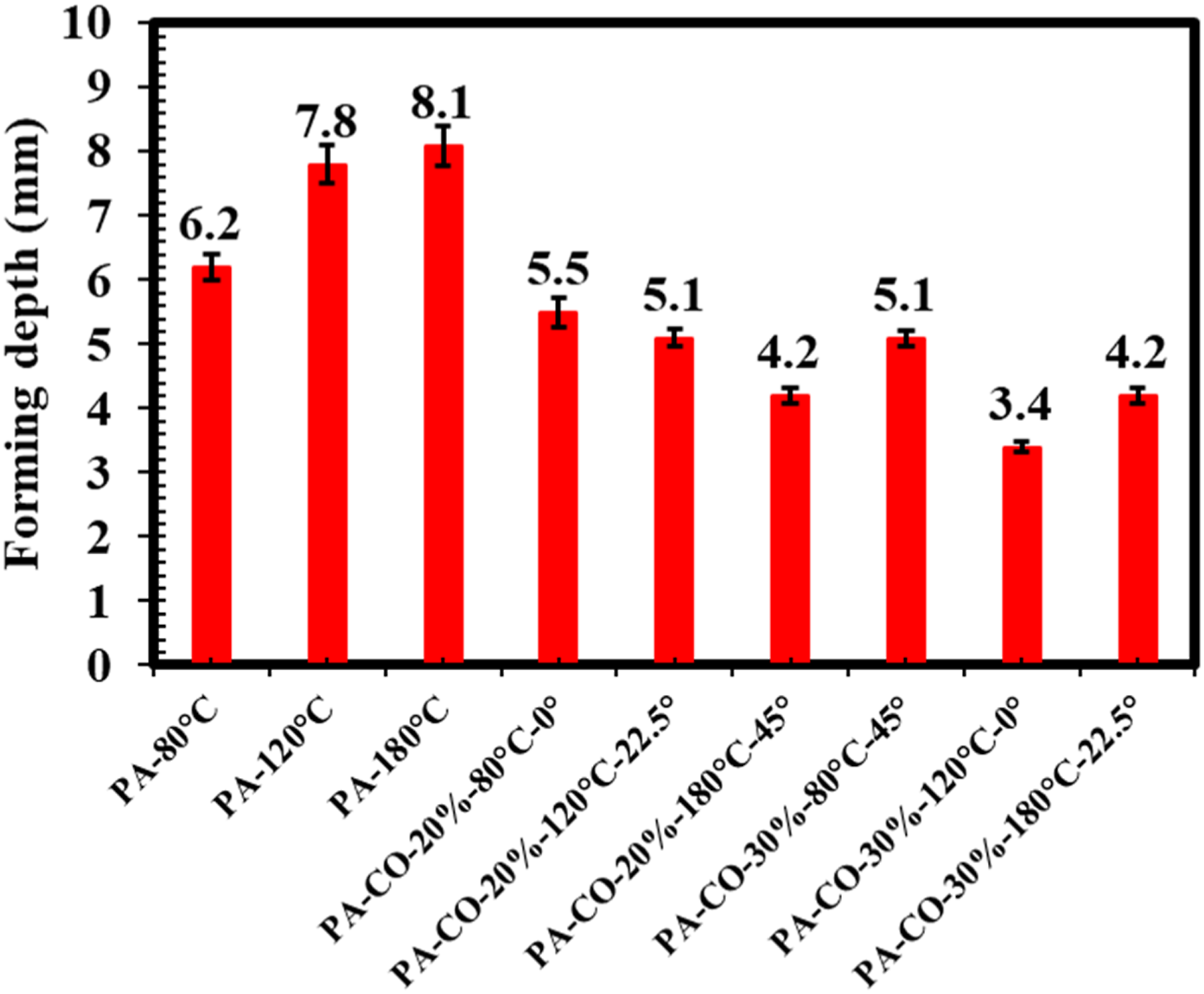
Experimental Validation of Numerical Investigation
In Figure 14, a comprehensive comparison is conducted between the simulated results and the actual formed samples. There is a clear alignment between the observed trend in forming depth in the experimental data and its counterpart in the simulated data. This alignment underscores the fidelity of the numerical simulations in accurately capturing the influence of the four key factors—namely, fiber weight fraction, process temperature, fiber orientation, and step size—on the SPWIF process applied to glass-reinforced PA6 sheets. Essentially, the simulations mirror the experimental outcomes, reinforcing the reliability of the model in replicating the intricate interplay of these factors in the SPWIF process. A comparison between actual deformed composite laminates and simulated ones.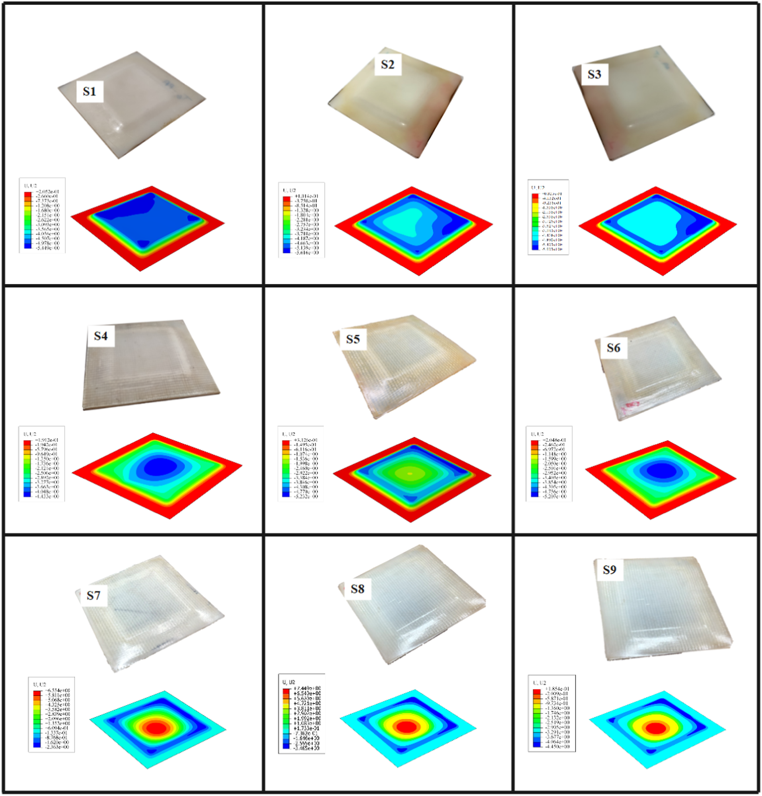
In Figure 15, a comparison is made between the experimental and simulated values of forming depth across various samples. The trends in simulation closely aligned with the experimental observations. Notably, as the temperature of the SPWIF process increased in the initial three samples, both the experimental and simulated forming depths exhibited a corresponding increase. Furthermore, the maximum prediction error was determined to be 10.26% for S2. This level of prediction error is not only deemed acceptable but also serves as evidence that the SPWIF process was effectively simulated, thereby warranting further investigation. Experimental and simulation value of forming depth for various samples.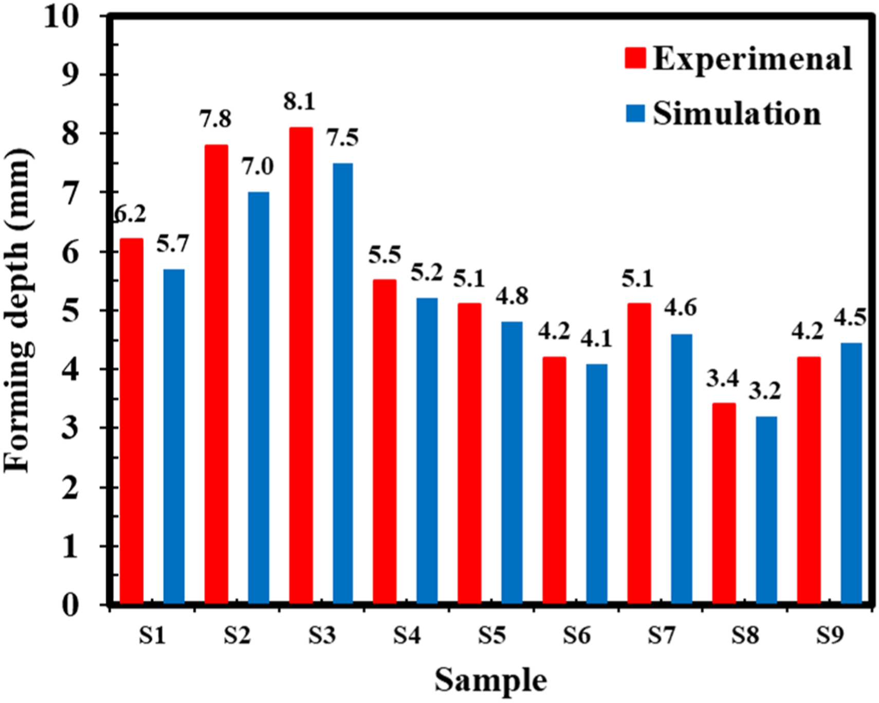
Figure 16 presents a comparative analysis of the thickness distributions in experimental and simulated data, using sample S1 as a reference and sample S4 as the selected specimen. Initially, both samples exhibited consistent behavior in the thickness distribution across various distances, affirming the accuracy of the SPWIF process simulation. Furthermore, the incorporation of glass fibers into PA6 led to a reduction in thickness distribution, with value decreasing from a 1.79 mm to 1.95 mm, a trend supported by both experimental and simulated data. Firstly, glass fibers enhance the overall stiffness of the composite material, making it less prone to stretching under the forming tool’s influence. Additionally, the high melting temperature of glass fibers provides better thermal stability, maintaining the integrity of the composite at elevated temperatures and reducing the rate of material flow and thinning. The presence of glass fibers typically reduces the ductility of the polymer matrix, resulting in less plastic deformation and a more uniform thickness distribution. Moreover, the thermal conductivity of glass fibers affects the heat distribution within the composite sheet during the SPWIF process, influencing the uniformity of thermal and mechanical behavior across the sheet. Lastly, glass fibers may bear a greater proportion of the load compared to the PA6 matrix at elevated temperatures, preventing excessive thinning around the fibers and contributing to a consistent thickness across the formed part. Essentially, this demonstrates that the reinforcing influence of glass fibers was accurately captured and reflected in the SPWIF process simulation. A comparison between experimental and simulated thickness distribution of (a) S1 and (b) S4.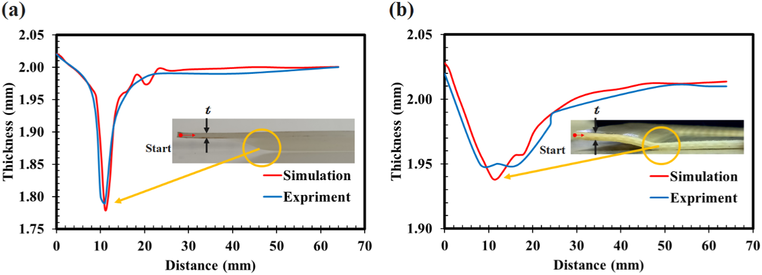
At an elevated temperature of 80°C for sample S4, fracture occurred at the cone’s tip in the upper steel sheet, leading to polymer extrusion due to thinning during the forming process. A visual comparison of the designed and formed geometries at two considered temperatures is presented in Figure 17(a). A conspicuous disparity between the designed and formed geometries is evident at the lateral wall of the samples near the large diameter of the truncated square pyramid. This discrepancy is primarily attributed to the bending effect around the edge of the backing plate. Similarly, when designed profile was subjected to simulation, it showed congruence with the design profiles in both experimental and simulated processes. Essentially, the SPWIF process for sample S4 continued until the upper steel sheet reached its maximum stress in both experimental and simulation scenarios, as depicted in Figure 17(b). Consequently, the observed deviation between the designed and formed geometries was incorporated during the simulation process. (a) Comparison between design profile of experimental and simulated of S4, (b) maximum stress on composite laminate during the SPWIF process of S4.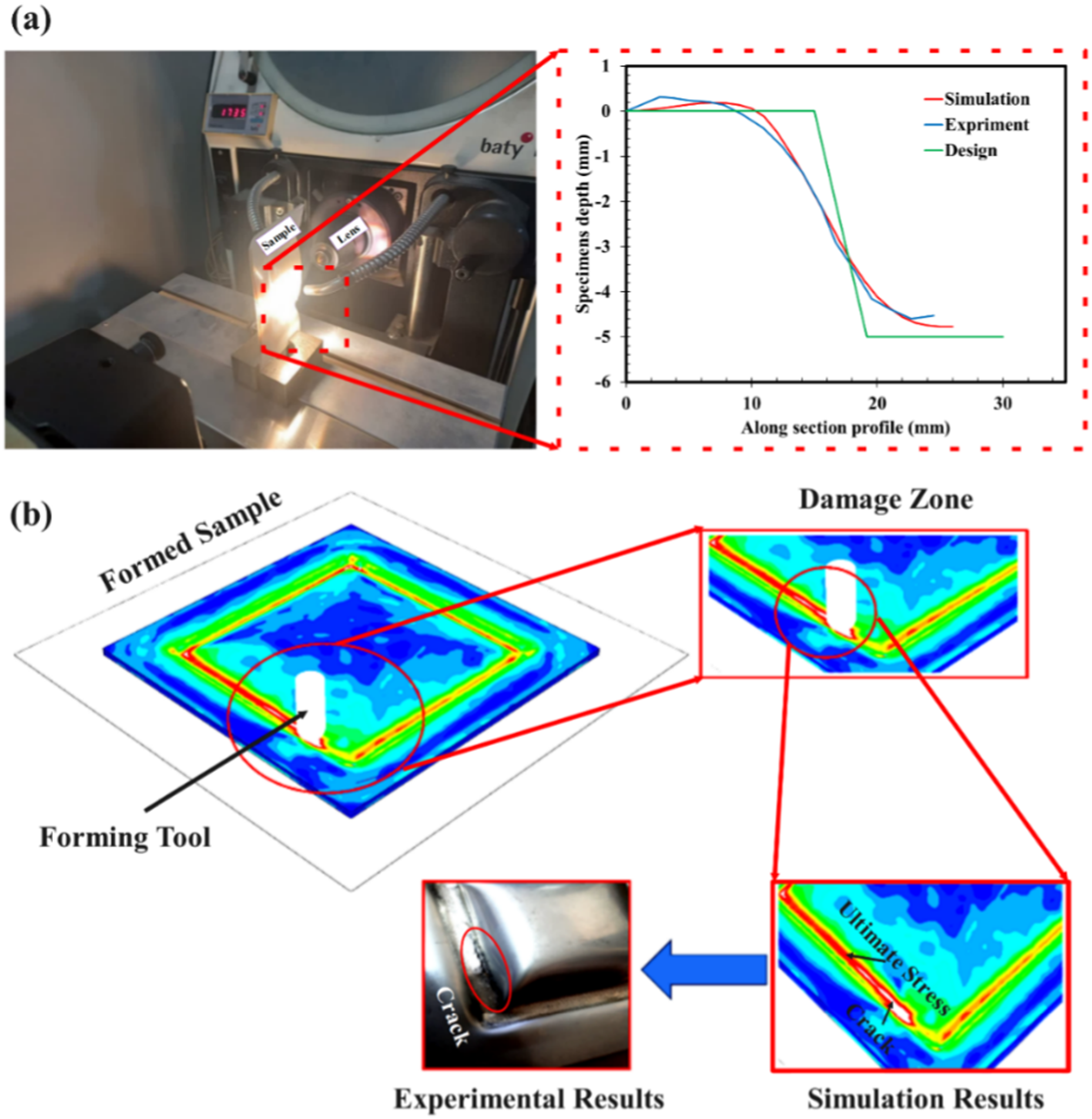
Figure 18 illustrates the force curves of Fx and Fz throughout the SPWIF process of sample S4. In Figure 18(a), the variation of the Fx force followed a pattern resembling a sine curve, with its magnitude depending on the positioning of the forming tool within a single contour. In Figure 18(b), as the forming tool penetrated the blank sheet, the Fz force experienced an immediate rise followed by a gradual increase until it reaches a peak. This phenomenon is primarily attributed to bending effects near the fixture’s edge and the incomplete contact interface between the tool and sheet during the initial contours. After reaching this peak, the Fz force steadily declined until material failure occurs. This behavior results from the simultaneous influence of four competing factors: material thinning and temperature increase induced by frictional heat generation work to diminish the required forming forces, while material strain-hardening and an increased wall angle of the design shape act to elevate these forces. Consequently, after reaching peak values, the dominant factors of material thinning and temperature increase led to a subsequent decrease in the Fz force.
26
Simulated force distribution of S1 and S4 (a) X force and (b) Z force.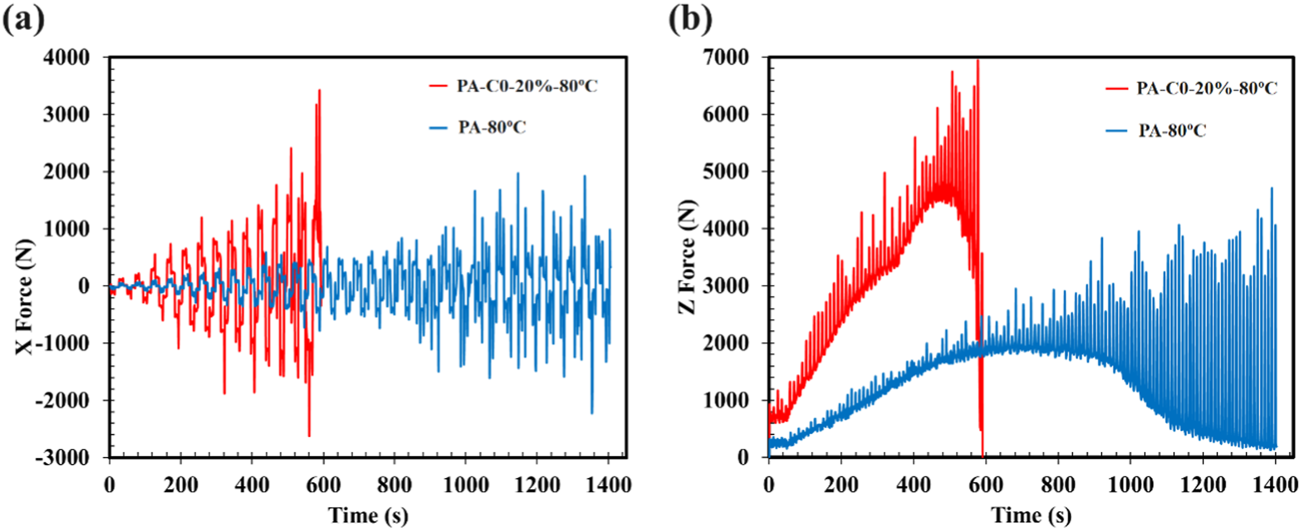
Conclusion
This study was conducted to explore the formability characteristics of glass fiber-reinforced PA6 sheets, manufactured through SPWIF methodology. Variations in fiber weight fractions, process temperatures, fiber orientations, and step sizes were analyzed using the Taguchi method. A numerical approach was employed to simulate the mechanical behavior of glass fiber-reinforced PA6 sheets under various temperatures. Subsequently, the RVEs of various samples were imported to simulate the SPWIF process. The following conclusions can be drawn:
The preeminent influence on the formability of glass fiber-reinforced PA6 sheets is attributed to the fiber weight fraction, which constitutes the most substantial contribution at 58.75%, whereas process temperatures exhibit the least impact, with a minimal contribution of 3.13%.
The proposed numerical simulations, which incorporate multi-scaling modeling of glass fiber-reinforced PA6 sheets and the SPWIF process, demonstrate an outstanding correlation with experimental findings.
Optimal conditions for the forming process are identified in a PA6 sheet featuring a fiber weight fraction of 20%, a process temperature of 80°C, a fiber orientation of 0°, and a step size of 0.50 mm. This configuration emerges as the most favorable due to its maximal forming depth value, reaching 5.5 mm.
Footnotes
Declaration of conflicting interests
The authors declare that there is no conflict of interest regarding the publication of this article.
Funding
The author(s) received no financial support for the research, authorship, and/or publication of this article.
Data availability statement
The data that support the findings of this study are available on request from the corresponding authors.