
Abstract
Recent advancements in the additive manufacturing (AM) technology have increased its utilization in various engineering sectors for the development of end-use products. However, the limited choice of available materials tends to limit its application domain. Addition of nanoparticles can significantly improve the material properties of the AM parts. Moreover, nanoparticles can be added in different stages of the process which will play an important role in determining the increase in material properties. This aspect of the stage-dependent addition of nanoparticles in AM process has not been fully explored. The present work discusses the effect of adding nanoclay in three stages of AM process namely preprocessing, on-site and post-processing stage. It has been found that the nanoparticles interact in a different way with the polymer and result in different structure, morphology and mesostructure of the nanocomposites. The approach can be utilized for achieving improved material properties of AM-fabricated parts.
Introduction
The fabrication of complex geometrical products possessing required performance characteristics has great industrial importance. In the past decade, additive manufacturing (AM) has evolved as a promising candidate for fabrication of intricate parts in reduced manufacturing lead time. Due to its potential, AM has progressed from prototyping to manufacturing of end-use products. AM via fused filament fabrication (FFF) process provides a platform to fabricate functional polymeric parts with minimal wastage of material. Simple fabrication method and commercialization of economical desktop machines have made the process popular compared to other AM techniques. Due to layer manufacturing technique, high complexity can be achieved, but on the other hand, the material and surface properties of FFF parts are compromised. Moreover, limited choice of available materials and their limited properties causes a constraint for end-use application of FFF parts. However, it is well known that inclusion of nanoparticle materials can enhance the properties of the polymer. 1 Utilizing the attributes of nanoparticles with the well-known advantages of FFF process may open avenues for fabrication of high-performance parts which will increase the application domain for the process.
Nanoclay is a versatile, naturally occurring, layered structured nanoparticle of clay. They have high surface area and possess high cation exchange capacity which improves its interfacial interaction with the host polymer. 2 Their 1-nm thick layers do not affect the optical transparency of the polymer in visible light; moreover, they provide a torturous path for gases which decreases the gas permeability. 2 Nanoclays are potentially capable to increase the mechanical properties even at low content (≤5 wt%). 3 Also it can enhance the thermal properties of the polymer such as heat deflection temperature. 4 Exfoliation of nanoclay can be achieved by delamination of the clay platelets, and their ability to orient along the extrusion direction leads to improved performance of the nanocomposite. 5 The presence of nanoclay can also improve the biodegradability rate of biodegradable polymers. 6
Its ability to be expanded makes it possible to achieve large surface area in polymer nanocomposite. Additionally, its compatibility with FFF processable polymers and improvement in properties with very low content loading without much affecting the processability 2 makes it a suitable candidate for FFF process.
The properties of polymer nanocomposites (PNCs) depend upon its characteristics such as its internal structure, dispersion of nanoparticles and their interaction with the polymer. These characteristics are significantly influenced by the synthesis method adopted for nanoparticle addition in polymer. PNCs are generally synthesized in a preprocessing stage prior to any manufacturing process. However, the added advantage of FFF process is that nanoparticles can be incorporated at different stages of the process. The stage at which nanoparticles are added will also play an important role in achieving improved material properties. Different nanocomposite internal structures will be formed and therefore the material properties will be influenced differently by introducing nanoparticles at different stages of the FFF process.
In initial attempt of adding nanoparticles in FFF printing media, nanoparticles of vapour grown carbon fibres were melt mixed with polymer in a preprocessing stage. 7 It was reported that the homogeneous dispersed nanoparticles increased the tensile strength and stiffness of the nanocomposite. Similarly, investigations have been carried out to incorporate nanoparticles of graphene and carbon nanotubes in preprocessing stage prior to FFF process. 8 –10 It was found that melt blended nanoparticles can significantly enhance thermal, electrical and mechanical properties of the polymer. For inclusion of fillers during the FFF process (on-site), few attempts have been done so far by impregnating fibres during the 3D printing process. It was reported that the mechanical strength increased compared to the pristine polymer. 11,12 Most of the literature related to post-processing of FFF parts are focused on improving the surface finish of parts. Recently, a lot of work is reported on improving the surface finish of FFF parts by chemical route. The surface finish of FFF parts was improved by immersing them in the diluted acetone. 13 Improvement in the surface finish along with the minor reduction in tensile strength was observed. Also, the ductility was increased due to the chemical treatment. Moreover, the flexural strength was increased because of post-treatment. In a similar attempt, Cunico et al. 14 studied the effect of chemical treatment on FFF parts. The fabricated parts were exposed to hot acetone solvent vapours. The effect of number of pass was studied and it was found that surface finish was improved by 70%. Ten minutes of pass resulted in the fusion of the 3D printed layers. Also, it was observed that the chemical attack increased the tensile strength up to 46%. The FFF parts were post-processed with the vapour of acetone in a vapour smoothing station. 15 They studied the effect of geometry, infill density and exposure time on surface hardness. It was found that maximum 11% increment in hardness can be achieved by the vapour treatment. Statistical analyses revealed that only infill percentage had a significant effect on the surface hardness. This increase was due to the reflow of the polymer chains on the surface of the treated parts. A thin layer was formed on the surface of the treated part. However, utilization of nanoparticles for post-processing still needs to be investigated.
The literature reveals that various strategies have been implemented to improve the performance of FFF parts. These strategies are adopted at different stage of FFF process. However, there is no literature available which compares the effect of stage-dependent addition of fillers on FFF parts.
Therefore, the present research work focuses on the effect of the stage-dependent addition of nanoparticles on structure, morphology and properties of the nanocomposites for FFF process.
In this study, three distinct approaches have been used for nanocomposite formation. These approaches are based on the stage of FFF process at which nanocomposites are formed. Clay nanoparticles were introduced in acrylonitrile butadiene styrene (ABS) polymer at three stages, namely preprocessing, on-site and post-processing.
Experimental
Materials
In the present study, nanoclay is used as the filler material in ABS polymer matrix. Nanoclay was purchased from Nanoshel Intelligent material Pvt. Ltd (Punjab, India) with a trade name of cloisite 30B. These nanoparticles are organically modified with quaternary ammonium salt with modifier concentration of 90 mEq/100 g clay. ABS used in the study was supplied by the 3D printer machine manufacturer (Creator Pro, Flashforge 3D Technology Co., Ltd., Zhejiang, China). The nanoparticle addition was done in three stages of FFF process (Figure 1).
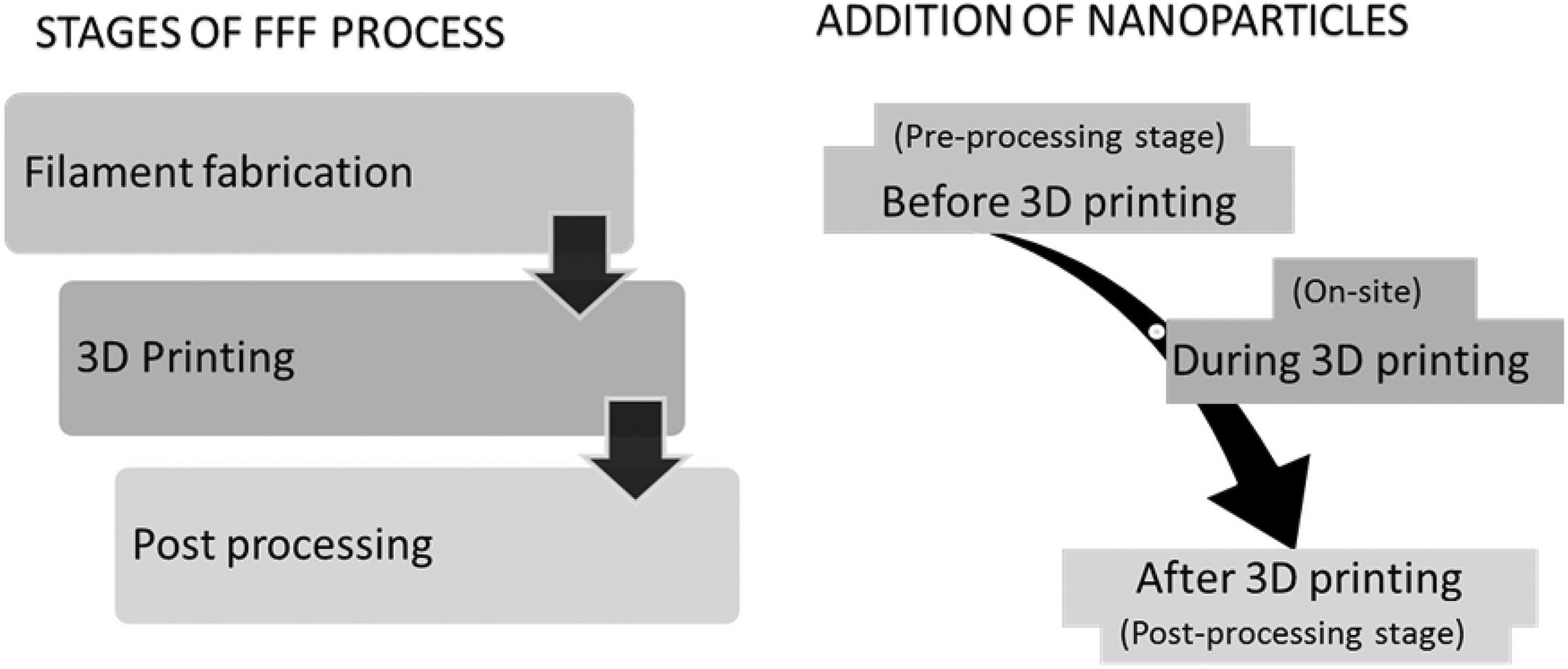
Nanoparticle addition in FFF process.
Methodology for nanoparticle addition
For nanocomposite formation in pre-processing stage, melt intercalation technique is used because of its environmental and industrial friendly attributes. The process involves mixing nanoclay with molten polymer under shear. During the process, polymer chain intercalates into the galleries of clay platelets. 3 The masterbatch strategy was used to overcome dispersion and agglomeration issues of nanoparticles in the polymer matrix. Preparation of masterbatch for developing nanocomposite is a decent strategy, which resolves the dispersion difficulties of nanofillers in polymer matrix and also provides better handling ability. 16 –18 The nanocomposite internal structure is made of intercalated polymer chains between the layered structure of nanoparticles. Therefore, on using the developed nanocomposite filament in FFF process, each deposited raster contains dispersed and intercalated organically modified montmorillonite (OMMT) nanoparticles within the polymer matrix. Figure 2(a) shows the schematic of nanocomposite formation in preprocessing stage. The polymer and nanoparticles were melt blended to form a masterbatch containing 1 wt% of nanoclay, which was diluted by further mixing it with polymer to obtain 0.1 wt% nanoclay. The filament (diameter 1.80 ± 0.5 mm) thus prepared was used for 3D printing of the specimens. Composite formation during FFF process requires the on-site interaction of fillers with the polymer filament. Therefore, fillers are generally added to the filament during the process by providing additional arrangements in the machine components. However, this increases the cost, since it requires an additional feeding mechanism. In the present work, a different approach has been adopted for on-site nanocomposite formation which eliminates the need for machine modification. The polymer filament was modified by coating it with the nanocomposite solution (Figure 2(b)). First, nanoclay was swelled in dimethyl ketone (DMK) solvent and simultaneously ABS polymer was solubilized in the same solvent. Further, the prepared solutions were mixed in a magnetic stirrer for 1.5 h. The prepared solution was coated on the ABS filament (diameter 1.75 mm) and after coating the diameter was 1.85 ± 0.04 mm. The volume percentage of coating was 10.5% and the clay content in solution used for coating the polymer filament contained 1 wt% nanoclay. Therefore, the developed nanocomposite contained 0.1 wt% nanoclay. During the FFF process, the coating present at the circumference of the filament diffuses with the inner ABS polymer as it is heated and also with the adjacent laid rasters. This creates a fused network of polymer and nanoclay over the entire fabricated part. To incorporate nanoparticles in post-processing stage of FFF process, the 3D printed parts were treated with nanoclay/DMK solution (Figure 2(c)). First, 0.79, 2.37 and 3.95 g of nanoclay were mixed with 100 ml of DMK separately to form three categories of solvent/nanoparticle solution. Then, the printed specimens were immersed for 30–70 s in the prepared solution in preliminary experiments to achieve approximately 0.1 wt% clay content in specimens for testing. The amount of deposited clay content will depend on immersion time, clay concentration and surface area of part. During treatment, the outer layers of fabricated parts get soft and the polymer chains slide over each other due to breaking of secondary bonds. At the same time, clay nanoparticles are deposited simultaneously on the surface. On solidification, the polymer structure is rebuilt containing embedded nanoclay. Thus the surface gets modified with the nanoparticles. The specimens were heat treated for 3 h at 60°C for removal of solvent before testing. The structure morphology and interfacial interaction of the nanocomposites were studied using X-ray diffraction (XRD), scanning electron microscopy (SEM) and Fourier-transform infrared (FTIR) spectroscopy to investigate the effect of stage-dependent addition of nanoclay for all the three stages of nanocomposite formation. The effect of nanoparticle on material and surface properties (tensile strength, Young’s modulus, elongation at break, hardness, relative permittivity and surface roughness) of the nanocomposites was investigated and compared with the pristine polymer. The tensile and hardness testing were done on specimens designed according to ASTM D 638-10 and ASTM D2240 standards (shore D scale), respectively. The tensile test was performed on Instron Tinius Olsen testing machine (India) and hardness was measured by Mitutoyo durometer (Shore D). The relative permittivity was tested on 20 × 1.2 mm2 disc-shaped specimens on an impedance analyser at 1 MHz. The surface roughness (R a) was measured on the top surface of the parts (across the printed direction) with cut-off length of 0.8 mm. The roughness measurement was taken with a Rugosurf 10G tester (Tesa, Switzerland). All the specimens were printed with 0° raster angle and with 100% infill. For mechanical, dielectric and surface roughness measurement, three replicates of each specimen were recorded.
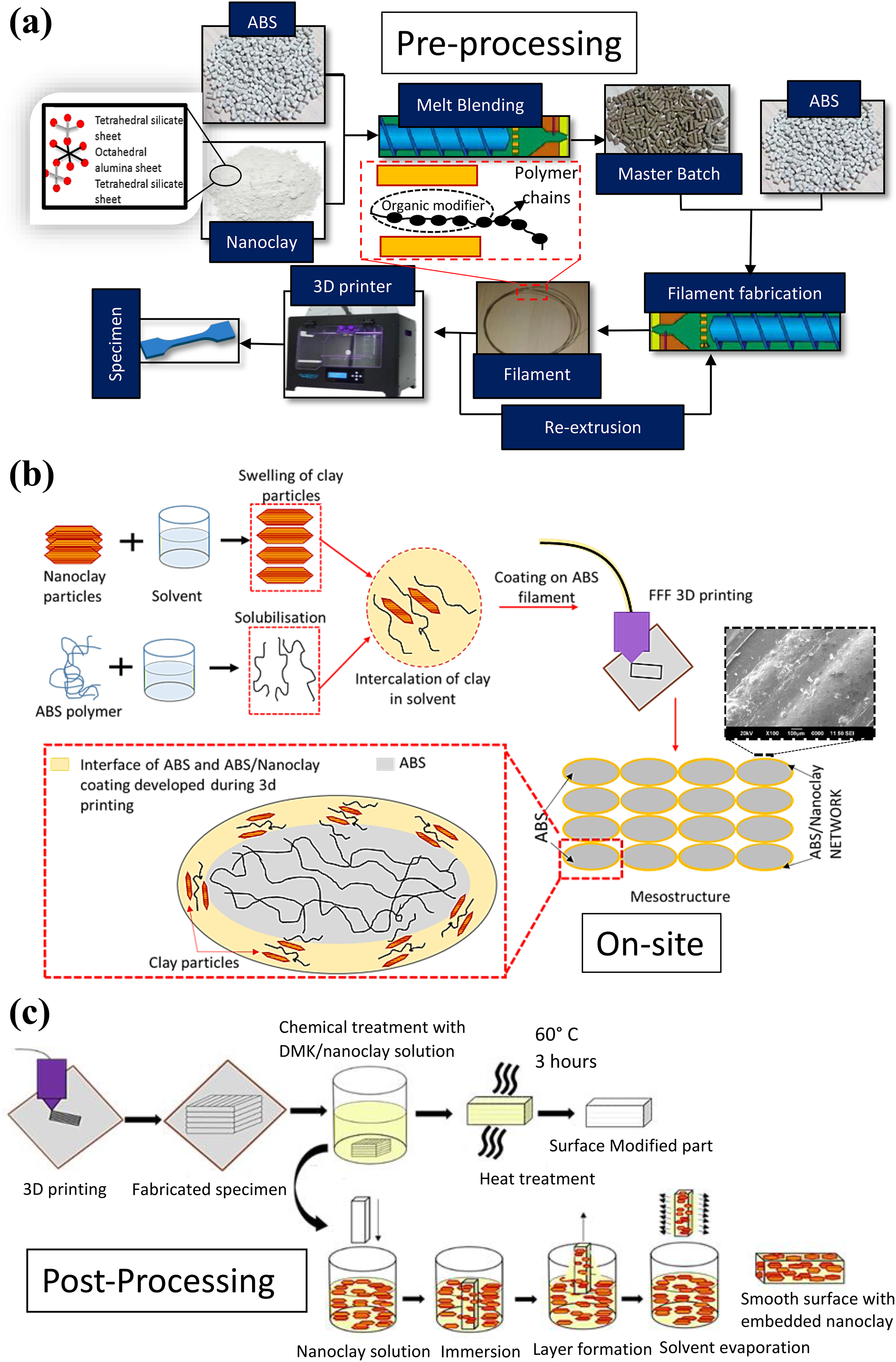
Schematic diagram illustrating the addition of nanoparticle in three stages of FFF process: (a) preprocessing stage, (b) on-site and (c) post-processing.
Results and discussion
Morphological analysis
The dispersion of nanoparticles within the ABS polymer matrix is observed by the SEM images of the top surface of the 3D printed nanocomposites. Figure 3 shows the SEM image of the preprocessed nanocomposite. The nanoparticle addition in preprocessing stage via melt intercalation process resulted in breaking of the nanoparticles into smaller tactoids and further resulted in delamination of the clay layers. 19 The nanoparticles were evenly dispersed over the entire observed region. The breaking of nanoclay particles during the processing results in better dispersion in the polymer matrix. Figure 4 shows the SEM image of nanocomposite developed during the on-site stage. It can be seen that the size of nanoclay particles is large compared to the size as obtained by preprocessing stage. It is clear that the shearing of clay particles can be obtained to a greater extent by melt processing compared to on-site nanocomposite development. However, this process helped to develop a unique mesostructure of 3D printed parts, which created a network of nanoparticles at the interface and top surface of deposited rasters (Figure 4). During post-processing of 3D printed parts with nanoparticles, the surface of the parts was completely covered with the clay particles. The morphology of the post-treated part showed complete resemblance with the flake-like structure of nanoclay. Figure 5 shows the SEM image of post-treated part with nanoclay.
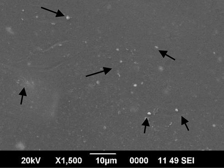
SEM image of preprocessed nanocomposite (black arrow shows the distribution of clay particles).
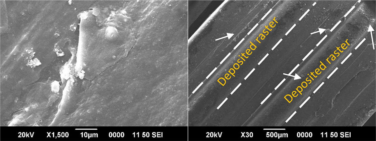
SEM image of on-site nanocomposite (left image) and top surface of deposited raster, white arrow shows the clay particles (right image).
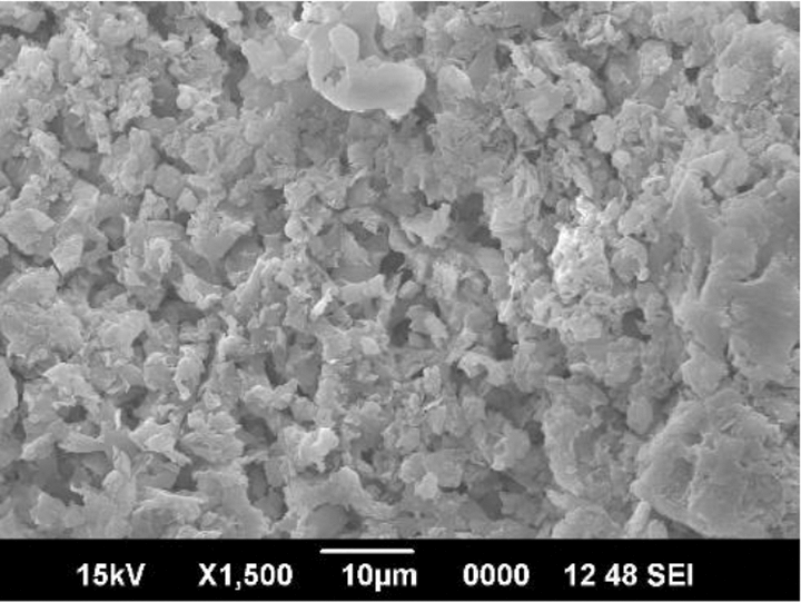
SEM image of post-processed part with nanoclay.
Structural analysis
The structure of nanoclay is made of stacked clay platelets which are held together by van der Waals’ forces. During processing of nanoclay, these platelets may or may not get separated. On separation, the interlayer distance of the platelets increases. The internal structure of the nanocomposites formed during the three stages was compared by the XRD data. Figure 6 shows the diffraction data for preprocessed nanocomposite. It can be seen that the peak of nanoclay present at 4.75° 2θ value 6 is not present in the nanocomposite which signifies that the platelets of the nanoclay are separated. This seems to be a plausible reason for exfoliation of the nanoclay particles. Also, the peak of nanoclay around 26° 2θ value was seen in the nanocomposite which confirms the presence of the nanoclay, as also seen by the SEM images. Figure 7 shows the XRD spectrum of nanocomposite developed during FFF 3D printing process. It can be seen that the peak position due to nanoclay is vanished which may be due to possible exfoliation. However, a small budging can also be seen, which may be due to the tactoids of clay particles. Therefore, it can be inferred that an intercalated structure with few tactoids was developed in nanocomposite formed during 3D printing. On observing the XRD spectrum of post-treated parts, it was found that the characteristic peak of nanoclay was present at 4.75° 2θ value (Figure 8), which signifies that the presence of nanoclay and also that the interlayer distance of clay platelets were not increased. This indicates that phase separation of nanoclay and polymer matrix resulted by post-processing.
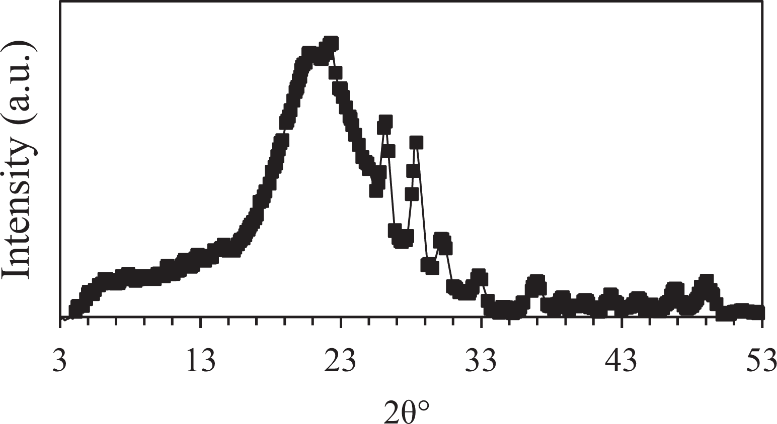
XRD spectrum of preprocessed nanocomposite.
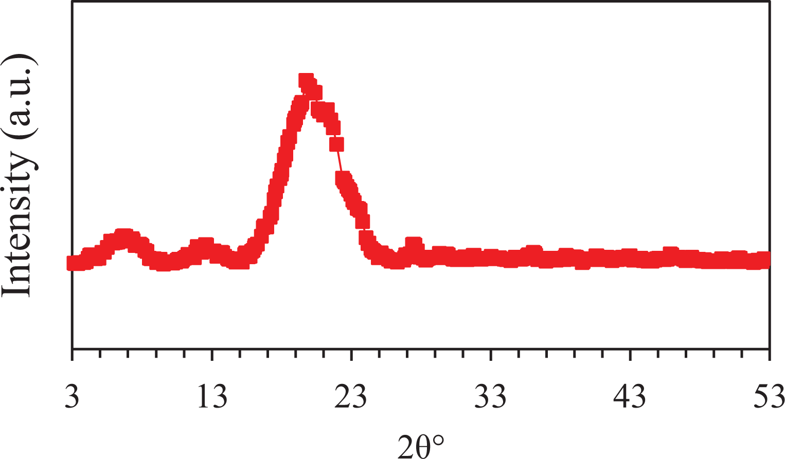
XRD spectrum of on-site nanocomposite.
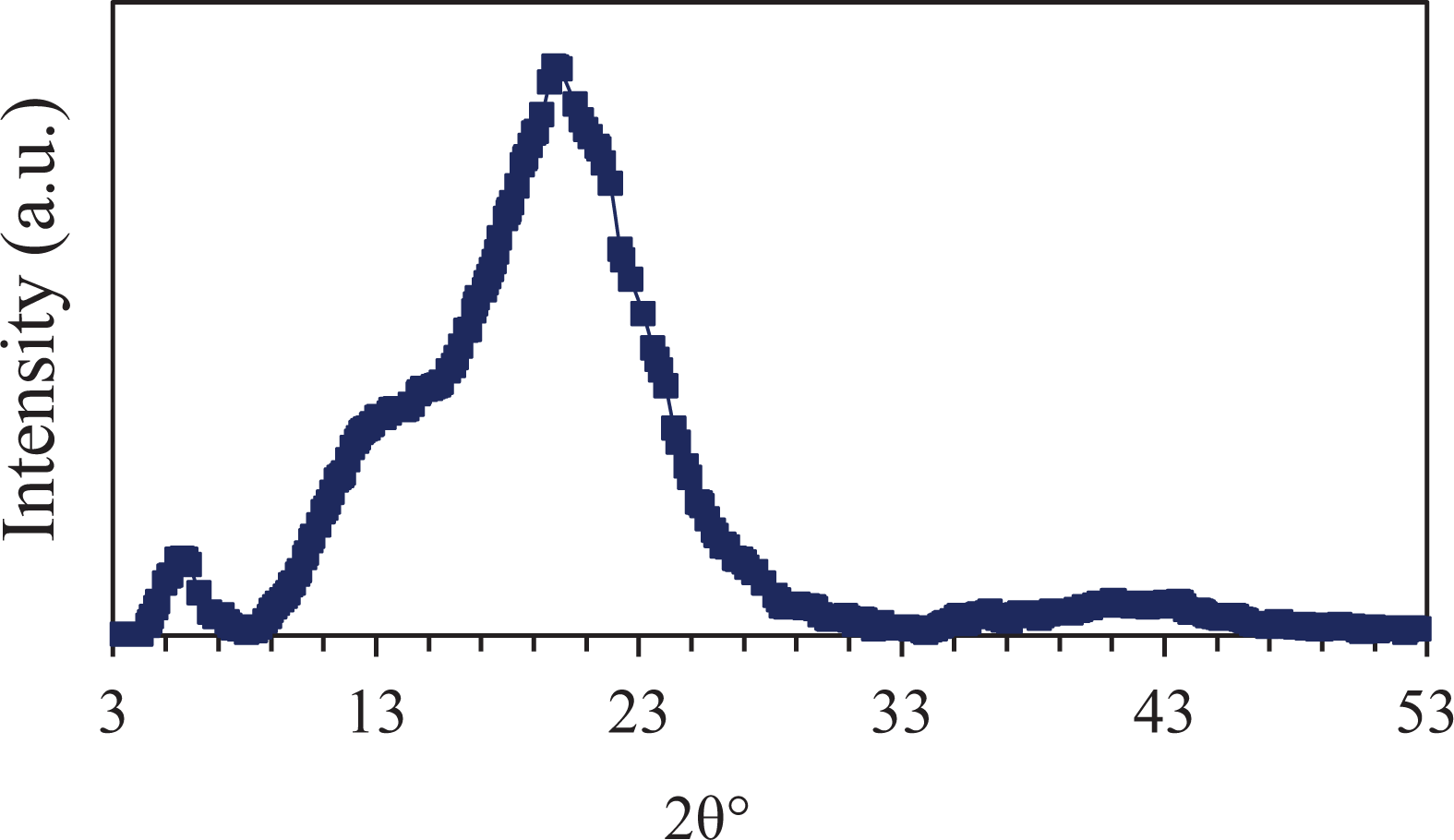
XRD spectrum of post-processed part.
Molecular components
The molecular components of the nanocomposites formed in all the three stages of FFF process were examined by FTIR analysis. The FTIR spectrum of the preprocessed nanocomposite is shown in Figure 9. The nanocomposite showed a peak at 594 cm−1 which correspond to Al–O stretching of nanoclay. 20 A peak around 1458–1519 cm−1 was observed which may be due to the overlapping of C–H vibrations of ABS polymer and organic modifier of nanoclay. 21 A broad peak around 1635–1782 cm−1 was also observed of the hydroxyl group of nanoclay and the carbonyl group of ABS polymer matrix. 22 A peak was observed at 2360 cm−1. This could be a possible hydrogen bonding between nitrile group of ABS and hydroxyl group of nanoclay. This interaction can lead to an increase in the mechanical properties of the nanocomposite. The peak due to O–H stretching of aluminosilicate was also present around 3600 cm−1. 22 The IR spectrum of nanocomposite developed during FFF 3D printing process is showed in Figure 10. The presence of Al–O stretching of nanoclay at 594 cm−1 was present in the spectrum. The peaks at 694, 910 and 964 cm−1 were present due to C–H of butadiene and styrene components of ABS polymer. 23 A peak of Si–O–Si of nanoclay was observed at 1026 cm−1. 20 Also, a broad peak around 1635–1782 cm−1 was observed. A similar peak at 2360 cm−1 was observed as in case of preprocessed nanocomposite signifying interaction of nanofiller and polymer matrix. 22 Due to C–H bond stretching vibrations of the organic modifier of nanoclay, peaks at 2854 and 2923 cm−1 were observed. 12 The peak due to O–H stretching of aluminosilicate was present at 3618 cm−1. 22 Figure 11 shows the IR spectrum of post-processed 3D printed parts. The band due to Al–O stretching was observed at 594 cm−1 as also seen in the above-mentioned cases. The peaks at 702 and 918 cm−1 can be attributed due to the C–H bond of polymer matrix. 23 A sharp characteristic peak of Si–O–Si of nanoclay was observed at 1018 cm−1. 20 Due to the embedment of nanoclay particles on the surface of the printed parts only phase separation has occurred, therefore, this peak was more intensified compared to composites developed by other routes. The peaks at 1450, 1488 and 1635 cm−1 were due to C–H vibration of polymer, C–H vibration of the organic modifier of nanoclay and O–H bending of nanoclay. 21,22 The peak due to C≡N due to acrylonitrile was present at 2237 cm−1. 23 Peaks at 2854 and 2923 were present because of C–H vibration of nanoclay and peak at 3363 cm−1 was due to the hydroxyl group of nanoclay organic modifier. 24
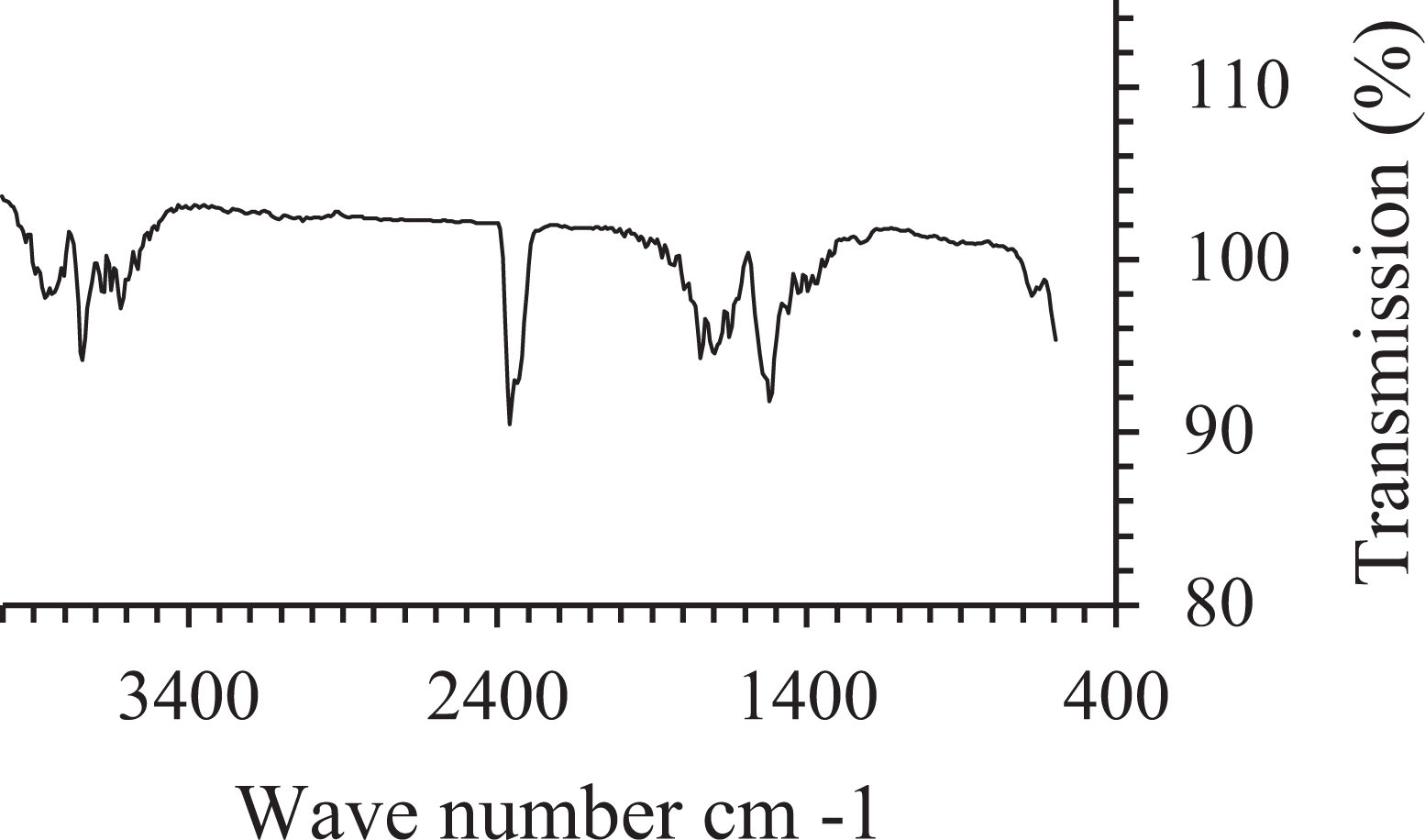
FTIR spectrum of preprocessed nanocomposite.
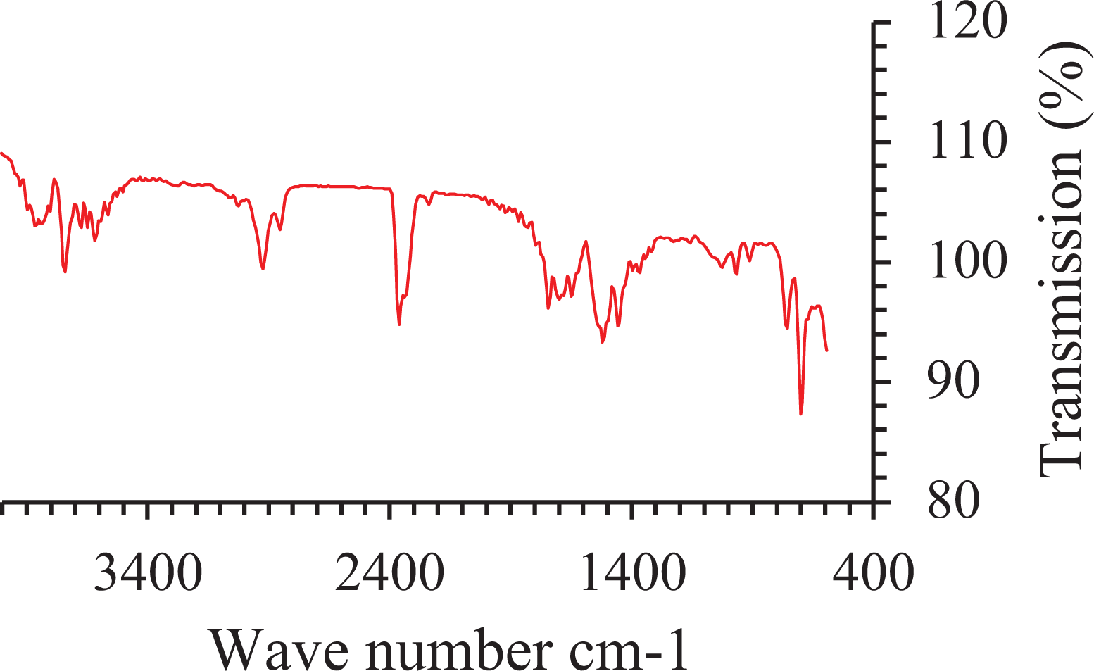
FTIR spectrum of nanocomposite developed during 3D printing.
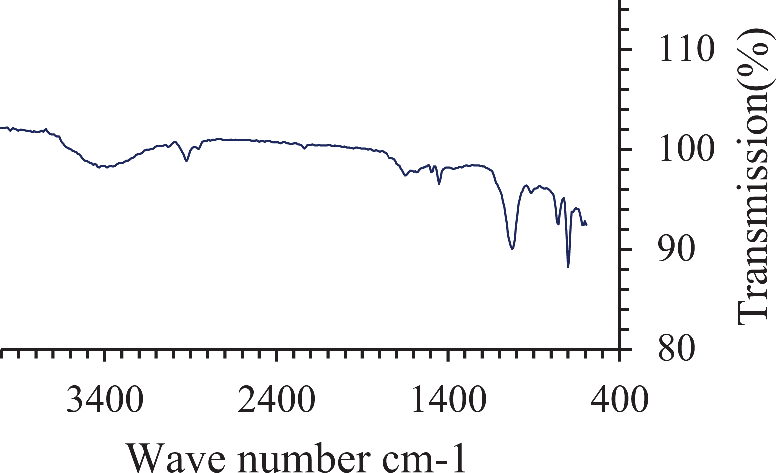
FTIR spectrum of post-processed part with nanoclay.
Mesostructure after 3D printing
Figure 12 shows the schematic diagram comparing the cross-sectional view of nanocomposites formed in all the three stages of FFF process. On nanocomposite formation in preprocessing stage, the filament itself contained homogeneously distributed nanoparticles. Therefore, in the mesostructure of 3D printed parts, the distribution of nanoparticles covered the entire cross section. The deamination of silicate layers during melt processing in preprocessing stage resulted in increased surface area of nanoclay which came in contact with the ABS polymer matrix. In the approach for on-site nanocomposite development, each polymer filament had nanoparticles at its circumference, and during 3D printing these nanoparticles fused with the polymer. However, the core of the filament was still pristine polymer. As the deposited rasters fused with the adjacent raster, a network of nanoparticle/polymer was developed at the interface and at the outer boundary of rasters. On post-processing via nanoparticle/chemical route, the nanoparticles were strictly deposited at the outer surface of the printed part. Surface smoothing of the outer rasters was obtained as the result of interaction of chemical with polymer along with the surface embedment of nanoclay at the same. However, delamination of nanoclay was not obtained in the process.
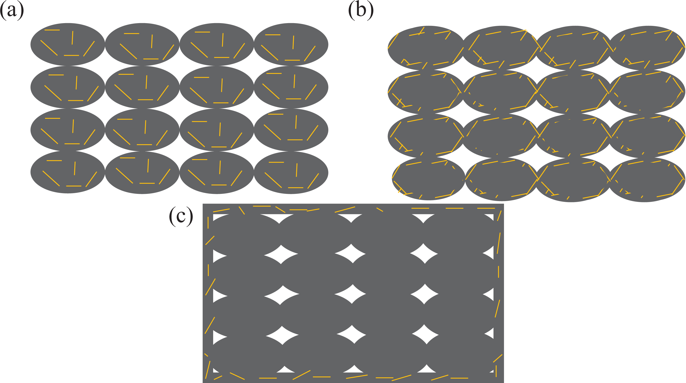
Schematic representing the distribution and mesostructure of nanocomposites formed at different stages of FFF process: (a) preprocessed, (b) on-site and (c) post-processed (yellow lines represent clay platelets and grey colour represents ABS).
Mechanical properties
Figure 13 shows the comparison between the stress versus strain graphs of nanocomposites formed at different stages of FFF process and pristine ABS. It can be inferred that the preprocessed nanocomposite showed maximum load bearing capacity followed by on-site nanocomposite and post-processed parts. This is because of good dispersion, exfoliation and interaction of nanoparticles with polymer matrix as achieved in preprocessing stage. 25,26 Figure 14 shows the comparison of mechanical properties for the nanocomposites. The tensile strength increased by 14.5% for preprocessed nanocomposite compared to pristine ABS. The tensile strength of on-site nanocomposite was same as pristine ABS (only 0.62% increase). However, the tensile strength decreased for post-processed nanocomposite. Similar trend was observed on observing the Young’s modulus. Preprocessed nanocomposite demonstrated 21.22% increase while post-processed parts showed significant decrease in modulus value. Also the modulus marginally decreased for on-site nanocomposite (5.82%). The elongation at break showed an inverse trend compared to strength and modulus. 27 The preprocessed parts showed decrease in elongation at break compared to other nanocomposites and pristine ABS. A decrease of 26.92% was seen in preprocessed parts. This can be due to the exfoliated clay layers which restrain large number of polymer chains. On the other hand, on-site and post-processed parts showed increase of 5.96% and 10.57%, respectively, compared to ABS. The increase can be due to the plasticizing effect of the residual solvent which increases the intermolecular distance of polymer chains. 28 The hardness of all the three printed nanocomposites showed increase compared to printed ABS. The nanocomposites showed 15.37%, 11.68% and 9.07% increase for preprocessed, on-site and post-processed nanocomposites, respectively.
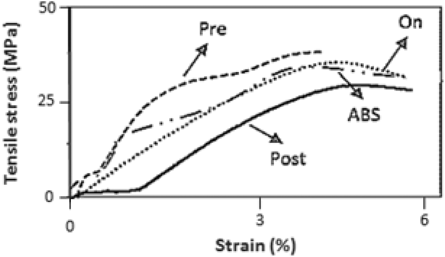
Comparison of tensile stress versus strain graphs.
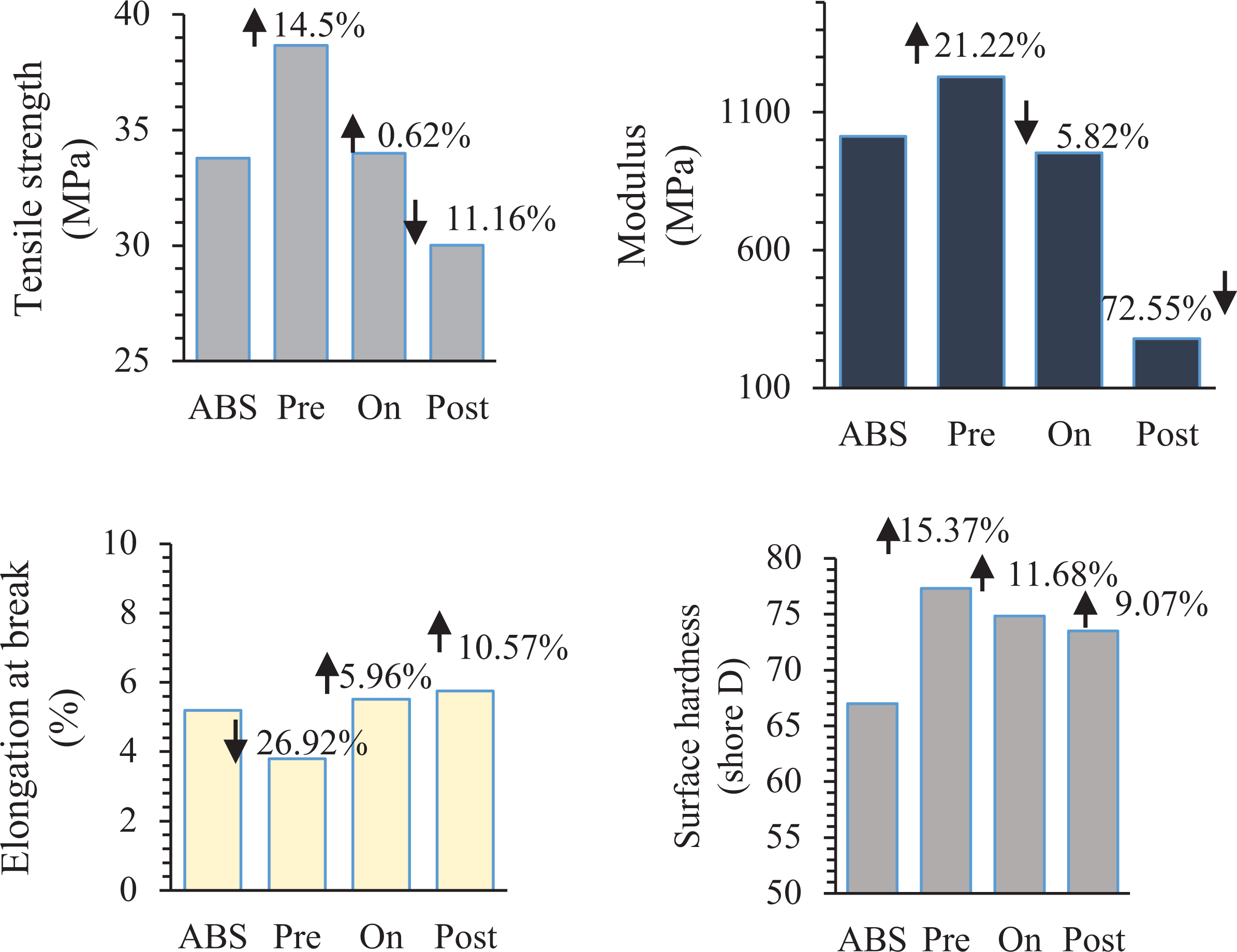
Comparison of mechanical properties.
Dielectric property
Figure 15 shows the comparison of dielectric properties of the nanocomposites formed at different stages of FFF process. The free ions present in nanoclay aids in enhancing the polarization of polymer and thereby increases its relative permittivity 29,30 in all the three stages of FFF process. However, the increase was maximum for on-site nanocomposite formation compared to other routes. This is due to the fact that the mesostructure developed during on-site nanocomposite formation did not suppress the polarization of polymer chains as in case of preprocessing. 31 An increase of 1.1 unit (45.45%) in permittivity value was achieved for on-site nanocomposite formation route. For pre- and post-processed parts, increase of 0.95 units (39.25%) and 0.61 units (25.20%) was observed.
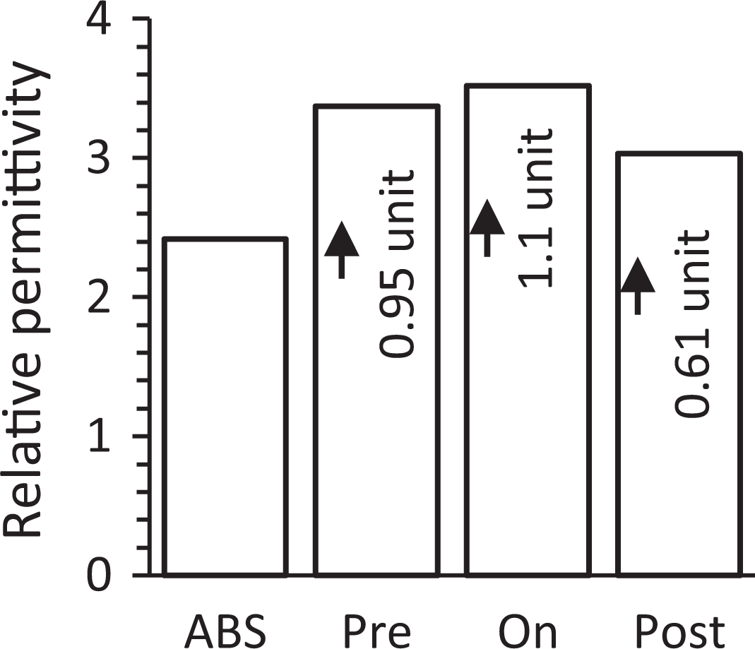
Comparison of relative permittivity.
Surface roughness
The effect of nanoparticle addition at different stages of FFF process on surface roughness is shown in Figure 16. The surface roughness of preprocessed and on-site nanocomposite increased compared to the parts printed by pristine polymer. The roughness increased more in the case of on-site nanocomposite route as the nanoparticles were present on the surface of the filament. And on 3D printing, these nanoparticles were distributed on the entire top surface of the part. The roughness tremendously decreased on post-processing the parts with nanoparticles and chemical. 14,32 A decrease of 94.24% in roughness value was achieved compared to the pristine polymer. A smoothing effect was achieved by the interaction of the DMK with the ABS polymer which resulted in improving the surface finish of the parts. The peak to valley height of outer printed layers obtained by 3D printing was reduced significantly as can be seen in Figure 16. In the other two cases of nanocomposite formation, these peak and valleys were present; therefore, the roughness was more compared to the post-processed parts. Table 1 shows the values of mechanical, dielectric and surface roughness testing of the samples along with the standard deviation.
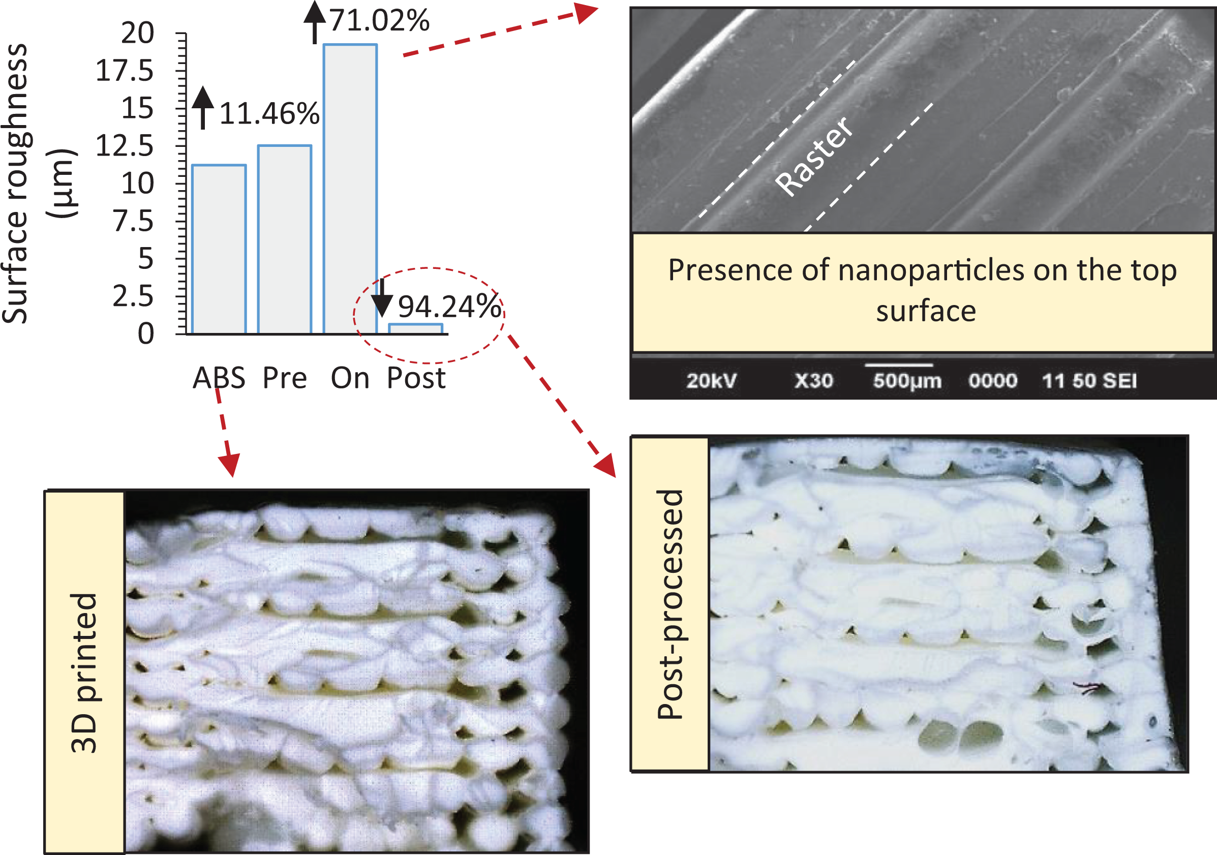
Comparison of surface roughness.
The experimental values of mechanical, dielectric and surface roughness testing of the samples along with their standard deviation.
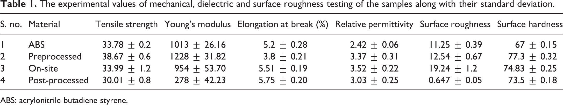
ABS: acrylonitrile butadiene styrene.
It can be inferred that the addition of nanoparticles at different stages of FFF process demonstrated different nanocomposite characteristics. Therefore, the achieved material and surface properties of 3D printed parts varied depending upon the nanocomposite formation route adopted. Figure 17 illustrates the major enhancement observed in material properties due to nanoparticle addition in different stages of FFF process. The methodology adopted for the entire study is presented by block diagram (Figure 18). The investigations carried out in this work will serve to fill the gap in the knowledge of nanoparticle addition in FFF printing media. It will increase the technological know-how of implementation issues and suitability of nanoclay for FFF process. The improved dielectric properties of the printed nanocomposite can be used in the development of miniature electronic components. Also, the improved surface properties of post-treated parts can find application in precision industry such as rapid tooling and investment casting. The improved mechanical properties achieved by preprocessing of nanocomposite can be utilized for printing of load bearing components and functional testing.
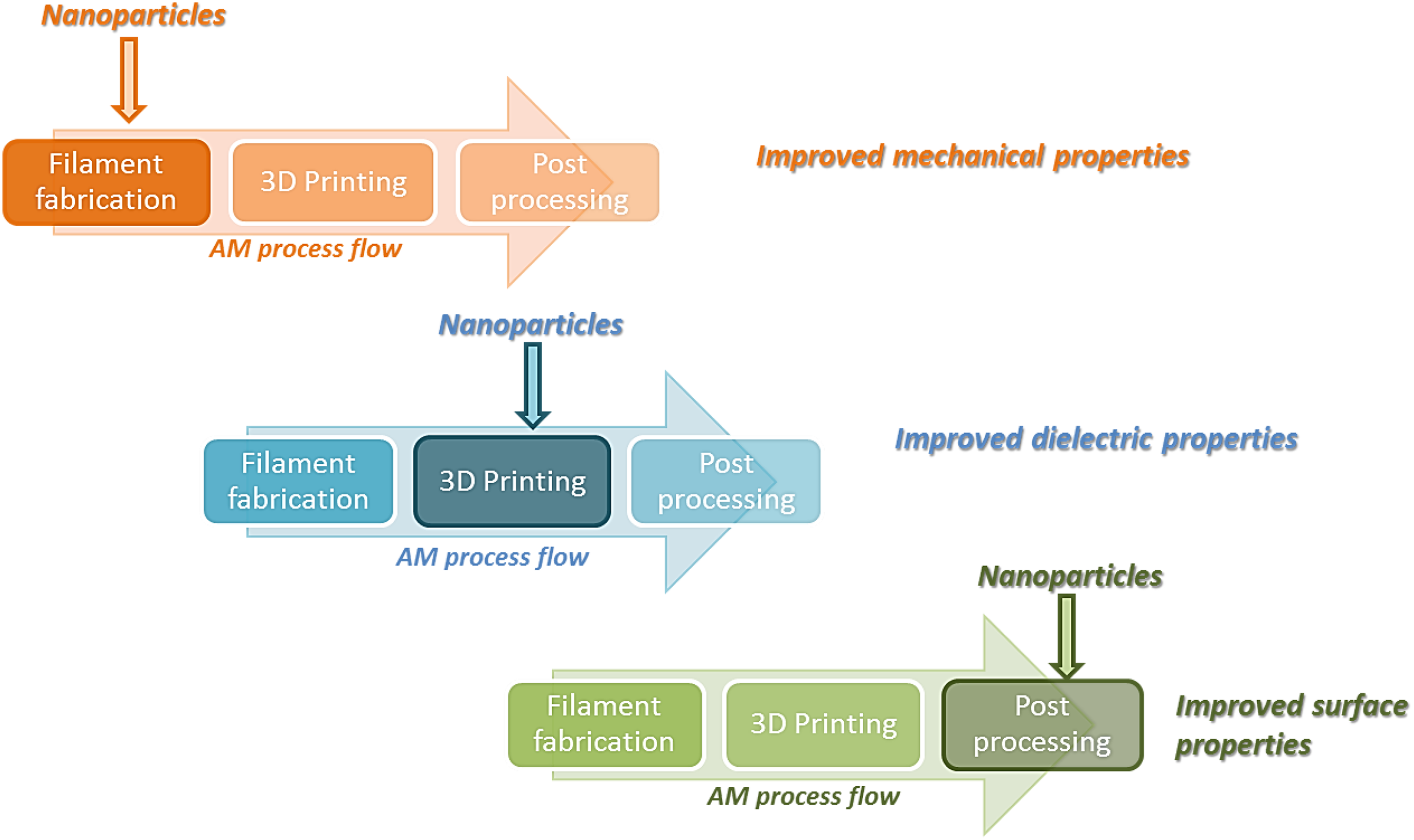
Major material properties affected by stage-dependent addition of nanoparticles.
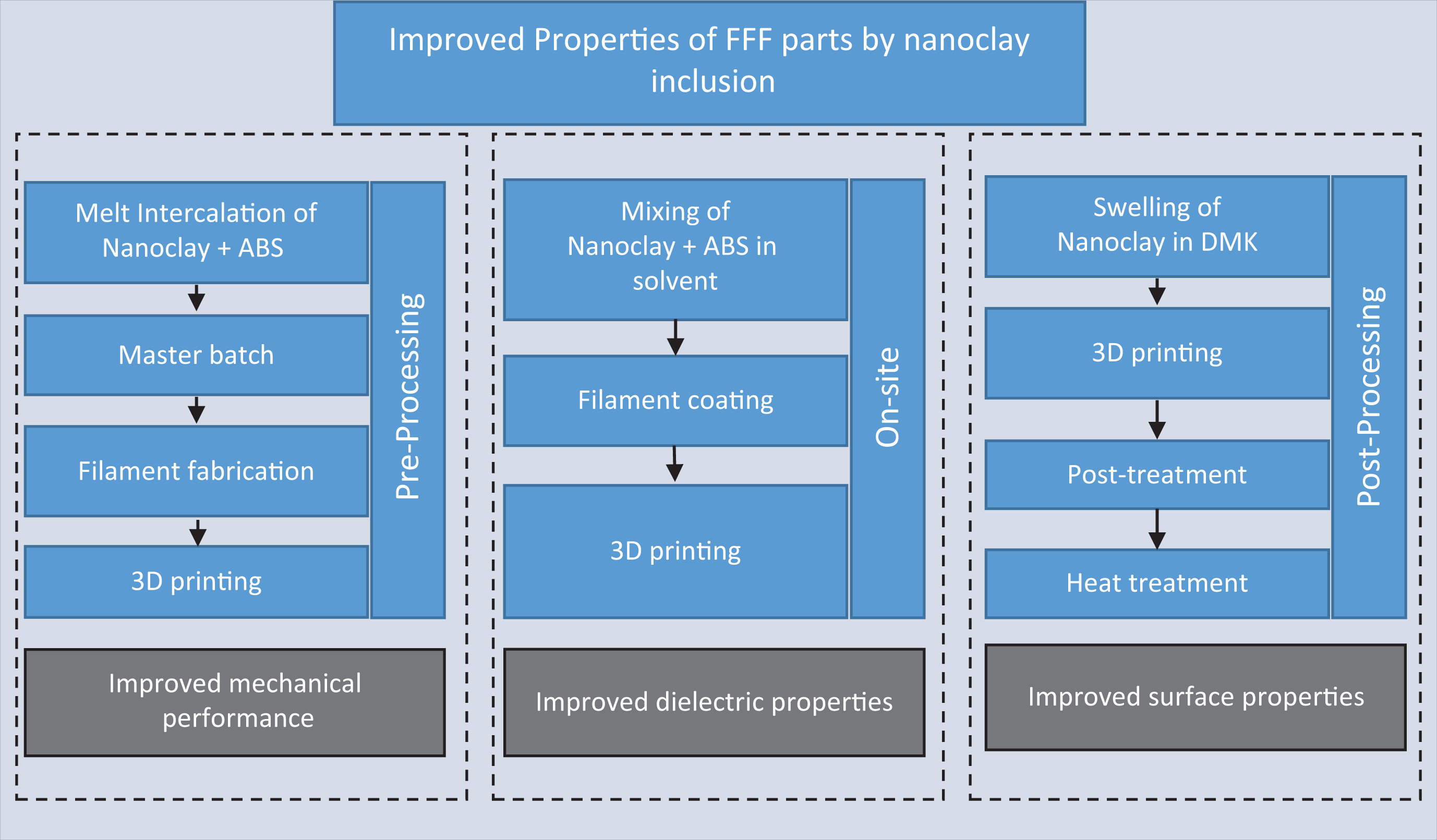
Methodology adopted for nanoclay inclusion in the present study and their effect on the properties.
In the present study, nanoparticles of clay are used with ABS polymer, in future other nanomaterials can be investigated for FFF process. Also, the effect of nanoparticle orientation can be studied on properties of printed nanocomposite.
Conclusion
The comparative analysis of nanocomposites formed at different stages of FFF process revealed that the stage at which the nanoparticle is added is crucial for determining the outcome in the material properties of the nanocomposite. The addition of nanoparticle in the preprocessing stage improved the mechanical properties of the polymer. However, the dielectric property was majorly enhanced when nanocomposite was formed during 3D printing.
Moreover, post-processing with nanoparticles enhanced the surface properties of the 3D printed parts. The change in the behaviour was due to the different morphology, distribution and interaction of the nanoparticles with the polymer matrix.