
Abstract
Fused Filament Fabrication (FFF) is the most prevalent additive manufacturing technique, which involves extruding a softened thermoplastic filament through the nozzle of a heated extruder. For improving the mechanical properties of the FFF-printed PLA parts one of the options is to add reinforcing material, such as carbonaceous materials or metal particles. The present study deals with analysing and comparing mechanical properties of carbon fibre reinforced poly lactic acid (CF-PLA), graphene reinforced PLA (Gr-PLA) and multi walled carbon nano tubes reinforced PLA (MWCNTs-PLA) composites by FFF. The selected process parameters used in this study are raster angle (0°, 45°, 90°), feed rate (20 mm/s, 40 mm/s, 60 mm/s) and layer height (0.1 mm, 0.15 mm, 0.2 mm) and based on different combinations, elongation at break, modulus and tensile strength are examined. MWCNTs-PLA exhibits overall maximum tensile strength, 37.438 MPa with 15.384% elongation at break for layer height 0.1 mm, raster angle 0° and feed rate 20 mm/s as compared to other selected specimens. Fractography analysis is also done to better understand the failure modes of specimens. To examine the dependency of the tensile strength on the process parameters, ANOVA, Taguchi’s L9 array Design of Experiment (DOE) is utilized indicating that layer height has the highest contribution of 56.713% for Gr-PLA, but raster angle has the highest contribution of 54.899% and 76.16% for CF-PLA and MWCNTs-PLA, respectively. This work will help in better understanding of how different parameters effects the material properties for PLA composites.
Introduction
Additive Manufacturing (AM) enables for the layer-by-layer manufacture of complicated shapes, starting with a virtual representation of the geometry to be printed. AM paves the way for the production of geometries that are impossible to produce using traditional subtractive technologies. 1 FFF is the most prevalent AM technique, which involves extruding a softened thermoplastic filament through the nozzle of a heated extruder. To construct the 3D object, the filament is put on a printing bed. PLA’s mechanical qualities must be enhanced in order for it to compete with other commonly used polymers.2,3 The well-known ways for modifying PLA performance include copolymerization, mixing, and the addition of fillers. Nanocomposites are materials that have at least one phase with ingredients that are nanoscale in size. Carbon nanotubes, for example, are a carbonaceous nanoparticle that has been actively explored as a candidate for incorporation into a host material because they have the ability to increase the host material’s electrical and thermal properties without sacrificing mechanical qualities. 4 Carbon Fibre (CF), graphene (Gr), multi walled carbon nano tube (MWCNT), carbon black, titanium dioxide, nano clay, and silica nanoparticles are some of the fillers that have been added to the PLA to improve some of its features. Several research have looked at the influence of CFs on the tensile properties of PLA, all of which show that adding fibres to PLA greatly improves its tensile strength and modulus.5–7 The balance of mechanical characteristics was achieved by adding nano fillers to a polymer matrix and fabricating polymer hybrid nanocomposites at the same time. In addition, adding nano fillers to a polymer for fabrication results in fascinating electrical, mechanical, and thermal properties.8–12
According to the literature, nanoparticles influence a host material’s varied properties, making it appropriate for applications ranging from high-strength mechanical components to electrical, electronic, and automotive parts, as well as industrial equipment. Due to the benefits of manufacturing materials with increased properties, the production of nanocomposite materials is currently at the forefront in research. The use of AM allows for the rapid and efficient delivery of nanocomposites with improved properties. Due to their remarkable mechanical capabilities and low density, reinforced polymers (RPs) have been widely recognised as a sort of novel engineering material. The interfacial interaction between fibres and polymers is largely responsible for mechanical characteristics.6,11,13–15 However, due to the production of an interphase region in the matrix close to the surface of the fibres, the interfacial interaction is also the weakest component of the composites, which can be related to the differing mechanical characteristics of matrices and fibres. Because of their unique qualities, such as physical strength and chemical stability, carbon nanomaterials, particularly CFs, MWCNTs and graphene, have been frequently exploited to improve interfacial contact.12,16,17 The basic building component of carbon nanotubes is graphene, which is made up of an atomically thin sheet of sp2 carbon. Single-walled carbon nanotubes can be thought of as a rolled-up graphene sheet, with its one-dimensional geometry enabling efficient reinforcement only in the length direction while MWCNTs have several layers of rolled-up graphene. 18
Graphene is highly rigid, has a high thermal conductivity, has no effective mass, is impervious to gases, has great charge carrier mobility, and is optically transparent. 19 All of these characteristics provide graphene a competitive advantage over other materials used in similar applications.20,21 MWCNTs, often known as nano fillers, are the most commonly used synthetic fillers. The addition of a filler to the polymers might cause a change in the matrix’s characteristics due to the filler-filler and filler-matrix relationship at the nano or micro scale.22,23 The dispersive strengthening of the matrix is another advantage of MWCNT inclusion. The higher conductivity of composites was due to the improved density and connections between the grains of conductive fillers, which allowed electric current to flow through the same cross section of composite with fewer losses. 24
The fibre content, length of individual fibres, orientation, extent of fibre intermingling, fibre to matrix bonding, and arrangement of both fibres all influence the attributes of a hybrid composite.25,26 Printability and strength of printed items are also dependent on good layer adhesion and a uniform distribution of any additives. Agglomerates do not clog the printing apparatus or generate weak areas in the printed material because additives are distributed uniformly. To add to the complexity of FFF printing, numerous printing factors such as raster angle, raster width, layer thickness, build orientation, infill density and pattern, feed rate, and air gap have a significant impact on the quality and mechanical qualities of the products.26–28 Nanocomposites may aid in the development of lightweight structural materials with functionality for electronic components, micro batteries, circuits, and electromagnetic shielding.29–31 The use of fibre or particle has been tried to improve the mechanical performance of 3D printed objects.
Design of Experiments (DOE) is a systematic method to ascertain the influence of input process parameters over a single or set of output responses with regard to the optimization of process parameters.3,32–34 Application of multiple DOE, including ANOVA, fuzzy logic, full factorial design, response surface methodology (RSM), and the Taguchi approach, was the key to optimising the FFF process parameters. The Taguchi approach differs significantly from traditional methods. While traditional approaches stress quality control and inspection during the printing process or after the printing is completed, this approach places more emphasis on the quality design of products and processes.3,34–36 The Taguchi design of experiments approach was frequently used to improve the FFF process parameter variables because of its robustness, tolerance, and dimensional control.37,38 By adjusting the FFF process variables like nozzle temperature, infill density, and printing speed, Maguluri et al. 39 applied the Taguchi method to achieve better tensile properties for PLA parts. Even still, detailed statistical investigations are needed for polymer composites.
The present study examines effect of reinforcement and process parameters to the mechanical performance of FFF-printed specimens. Therefore, comparison of mechanical properties for CF-PLA, Gr-PLA, and MWCNTs-PLA composites is done by varying key parameters such as RA (raster angle), FR (feed rate), and LH (layer height), and then performing high-resolution microscopy of the fracture surfaces for better understanding of failure modes. The tensile test data is analysed using ANOVA and Taguchi’s approach to examine the dependency of mechanical properties to the varying process parameters.
Material and methods
Fused filament fabrication, is a material extrusion process that is used to produce solid shapes. CF-PLA (CF 20% by weight), Gr-PLA (Graphene 20% by weight) and MWCNTs-PLA (MWCNTs 20% by weight) filaments with 1.75 mm diameter are utilized in this experiment. The main reason for selecting 20% reinforcements is because the outcome will help in understanding better material for electrochemical energy storage devices. The specimen was shaped using the Cubic3D CUB 5.5 3D printer having 0.4 mm nozzle diameter. The specimen was created using SOLIDWORKS 2019 and Simplify3D software. The ASTM D638 type 1A specimens were prepared for tensile testing to examine the outcome of varying RA, FR, and LH. The nozzle extruded the material and can traverse horizontally with the build platform, which provides the vertical movement while depositing a layer and the traversing on to the subsequent layer once that layer is completed.
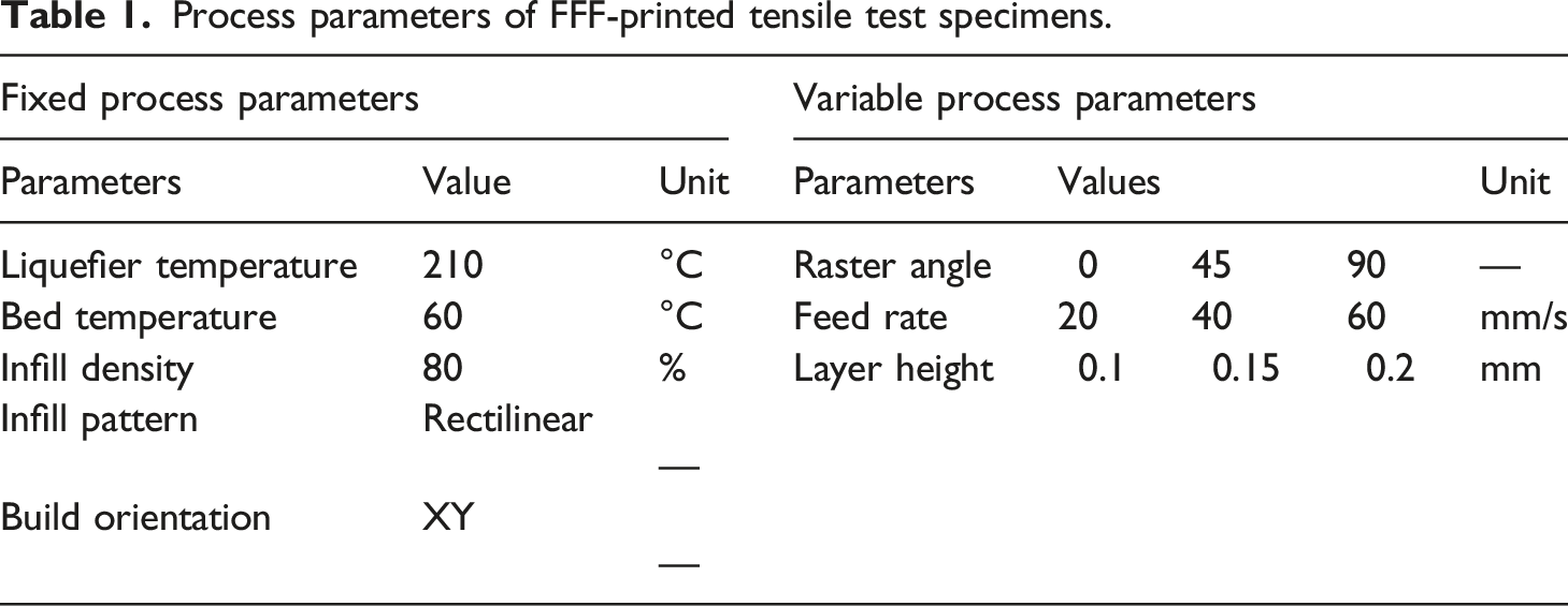
Process parameters of FFF-printed tensile test specimens.
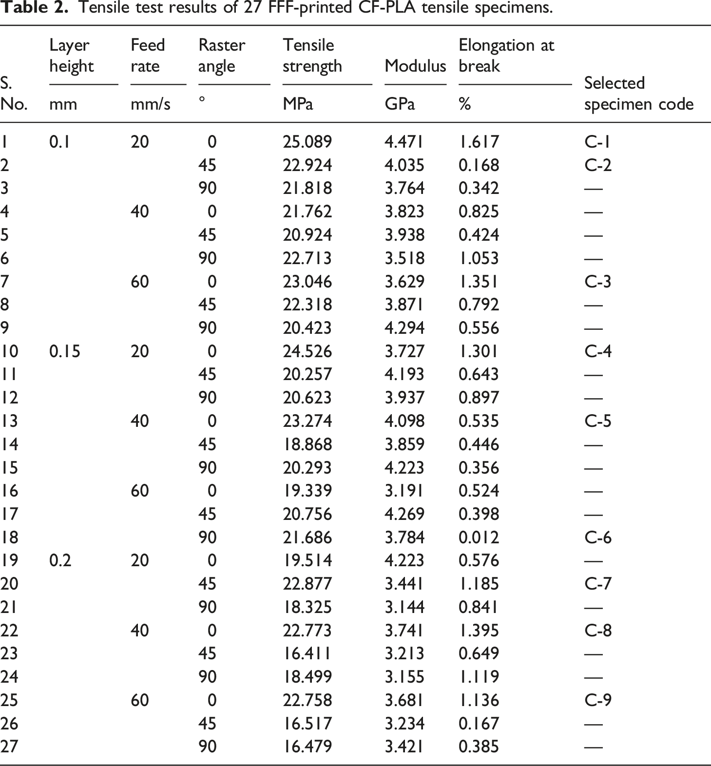
Tensile test results of 27 FFF-printed CF-PLA tensile specimens.
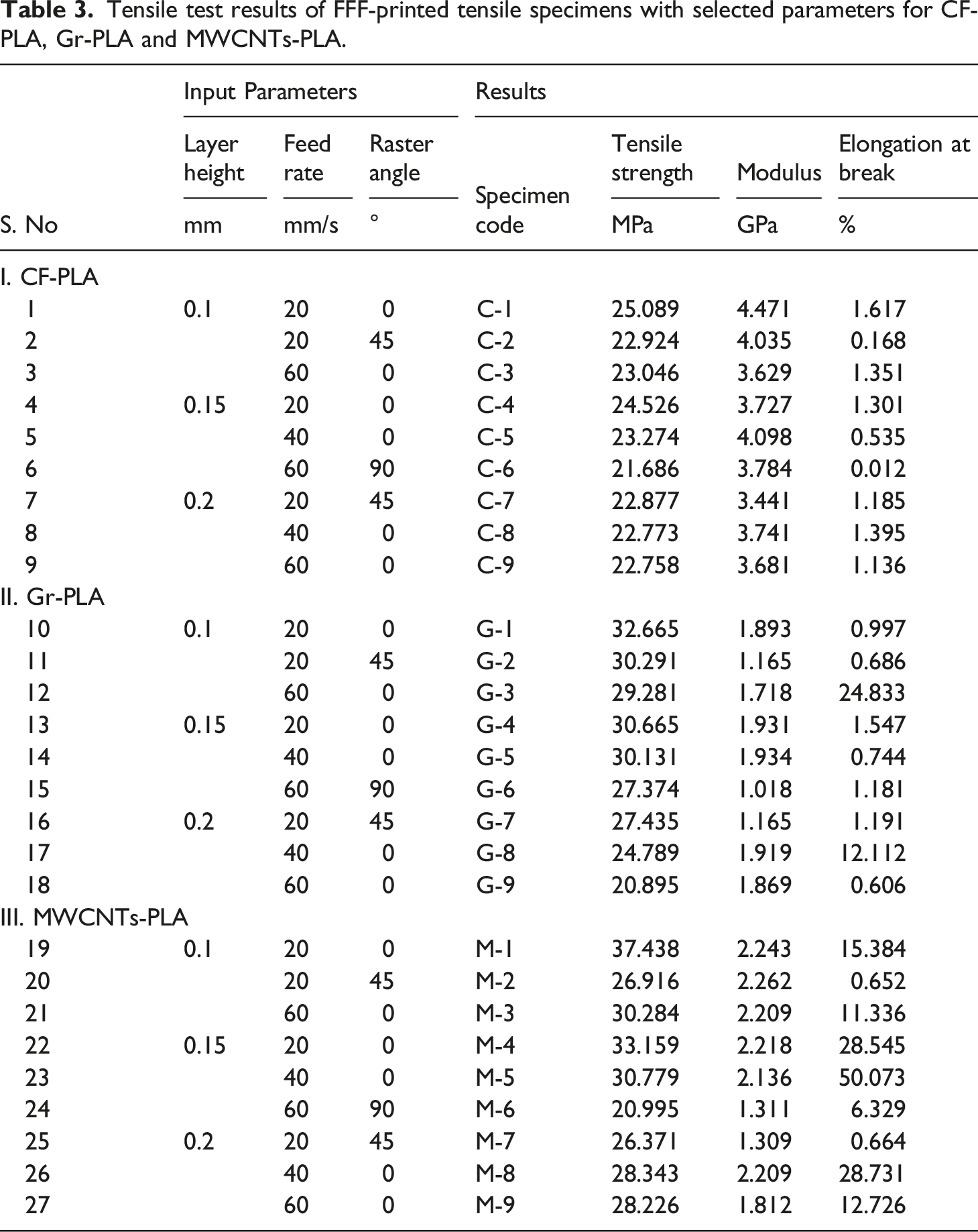
Tensile test results of FFF-printed tensile specimens with selected parameters for CF-PLA, Gr-PLA and MWCNTs-PLA.
The complete research methodology for experimental work is shown in Figure 1. Process flow chart for experimental work.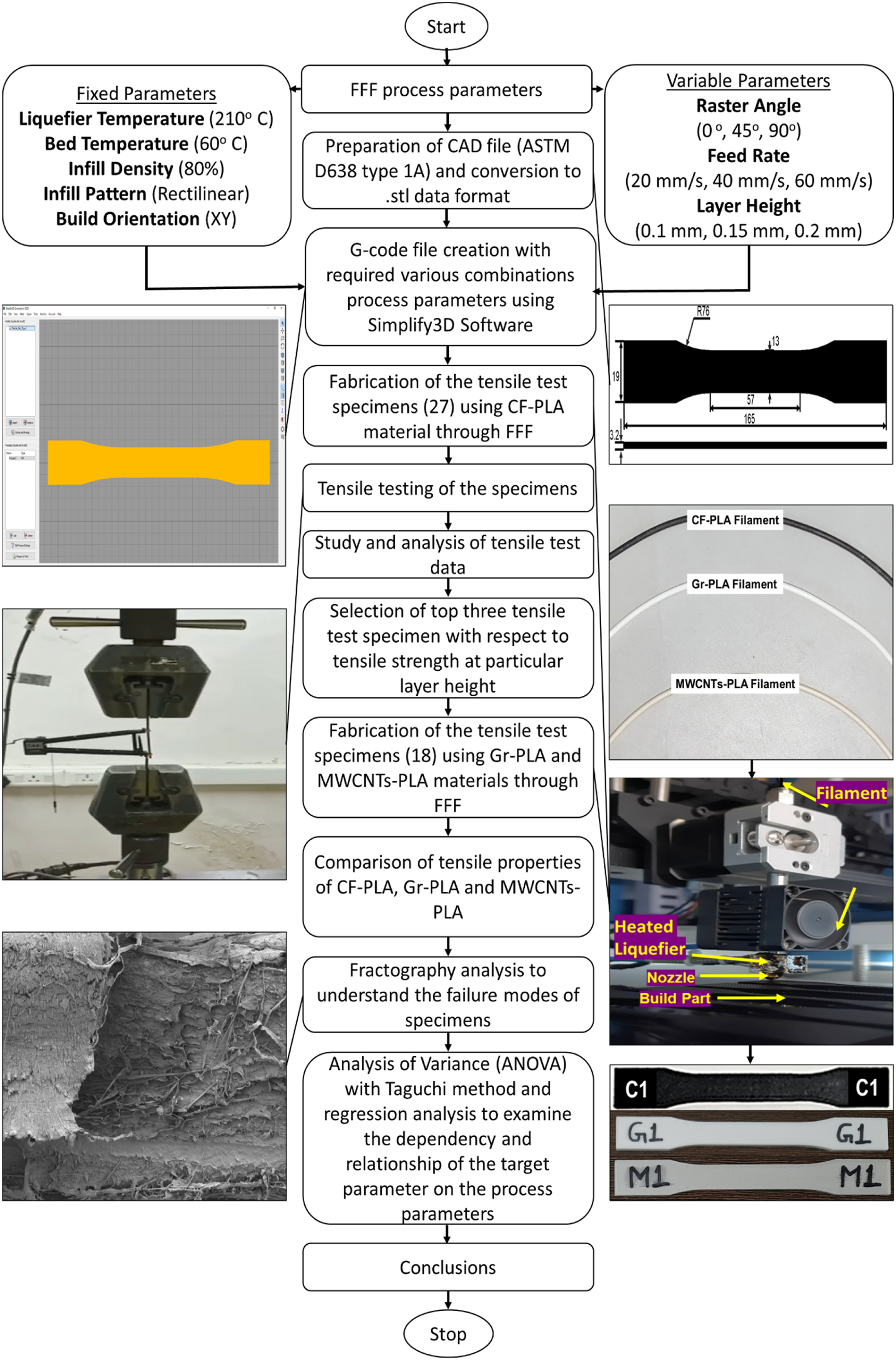
Result and discussion
The total 27 specimens are utilized with the combinations of the selected process parameters viz RA (0°, 45°, 90°), FR (20 mm/s, 40 mm/s, 60 mm/s) and LH (0.1 mm, 0.15 mm, 0.2 mm), Table 2, using the CF-PLA as fabricating material. The variation of stress versus strain is shown in Figure 2 for CF-PLA specimens. Stress strain graph for 27 CF-PLA specimens at different LH. (a) LH 0.1 mm, (b) LH 0.15 mm, (c) LH 0.2 mm.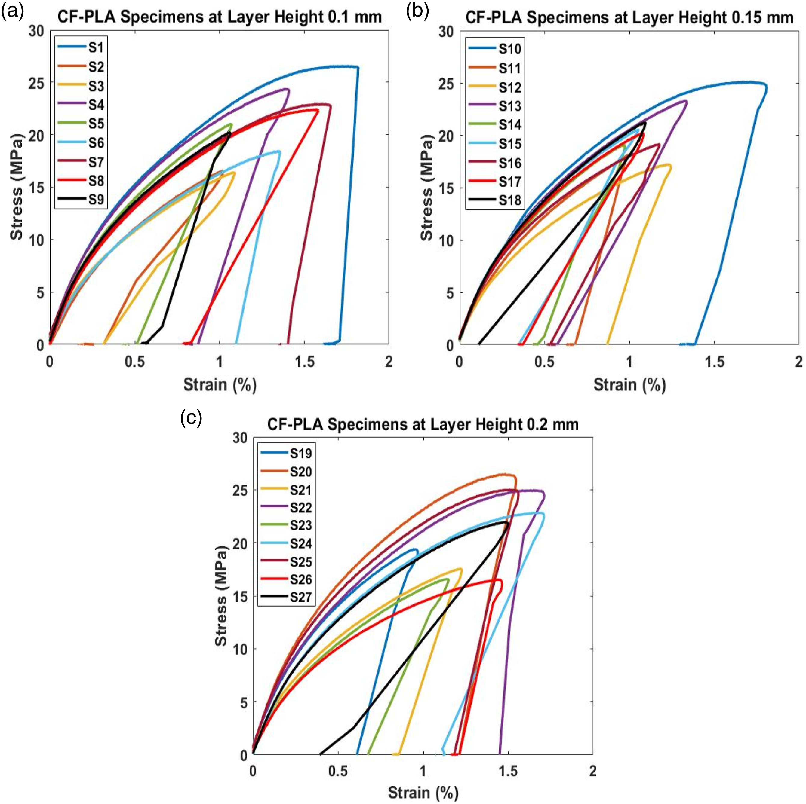
For all CF-PLA tensile test specimens, graphs indicate similar trend and variation. The minimum tensile strength observed is 16.411 MPa with 0.649% elongation at break and maximum tensile strength is 25.089 MPa with 1.617% elongation at break, therefore by altering the various process parameters, tensile strength is enhanced by 52.88%. Now, 9 parameters combination are selected from 27 combinations to analyse performance of other selected fabricating material. Utilizing nine selected process parameters, Table 3, and three fabricating materials (CF-PLA, Gr-PLA and MWCNTs-PLA) tensile testing and analysis of the tensile data is performed in below sections.
Effect of Layer Height
LH is a significant process parameter in the FFF process. In this experiment three values of LH are utilized viz 0.1 mm, 0.15 mm and 0.2 mm as it influences printing time and mechanical qualities of printed parts.
CF-PLA
The tensile strength of the material reduces as LH increases. The tensile strength is 23.046 MPa (C3) with 1.351% elongation at break for LH 0.1 mm (FR = 60 mm/s and RA = 0°) which is 1.27% higher while comparing with the tensile strength of 22.758 MPa (C9) with 1.136% elongation at break for LH 0.2 mm (FR = 60 mm/s and RA = 0°), Figure 3(a). This is because a reduced LH causes a broader bonding surface between layers, which strengthens bond and consequently the capacity to resist more tensile force. Low % elongation at break and low stiffness have also been seen at higher LHs. At FR = 40 mm/s and RA = 0°, tensile strength achieved is 23.274 MPa (C5) with 0.535% elongation at break for LH 0.15 mm which is 2.2% higher while comparing with the tensile strength of 22.773 MPa (C8) with 1.395% elongation at break for LH 0.2 mm, Figure 3(a). An elevation in layer thickness diminishes the interlayer bonding of the FFF-printed CF-PLA material which results in reduced tensile strength. Stress strain graph for tensile test specimens with selected process parameters for different fabricating material (a) CF-PLA, (b) Gr-PLA, (c) MWCNTs-PLA.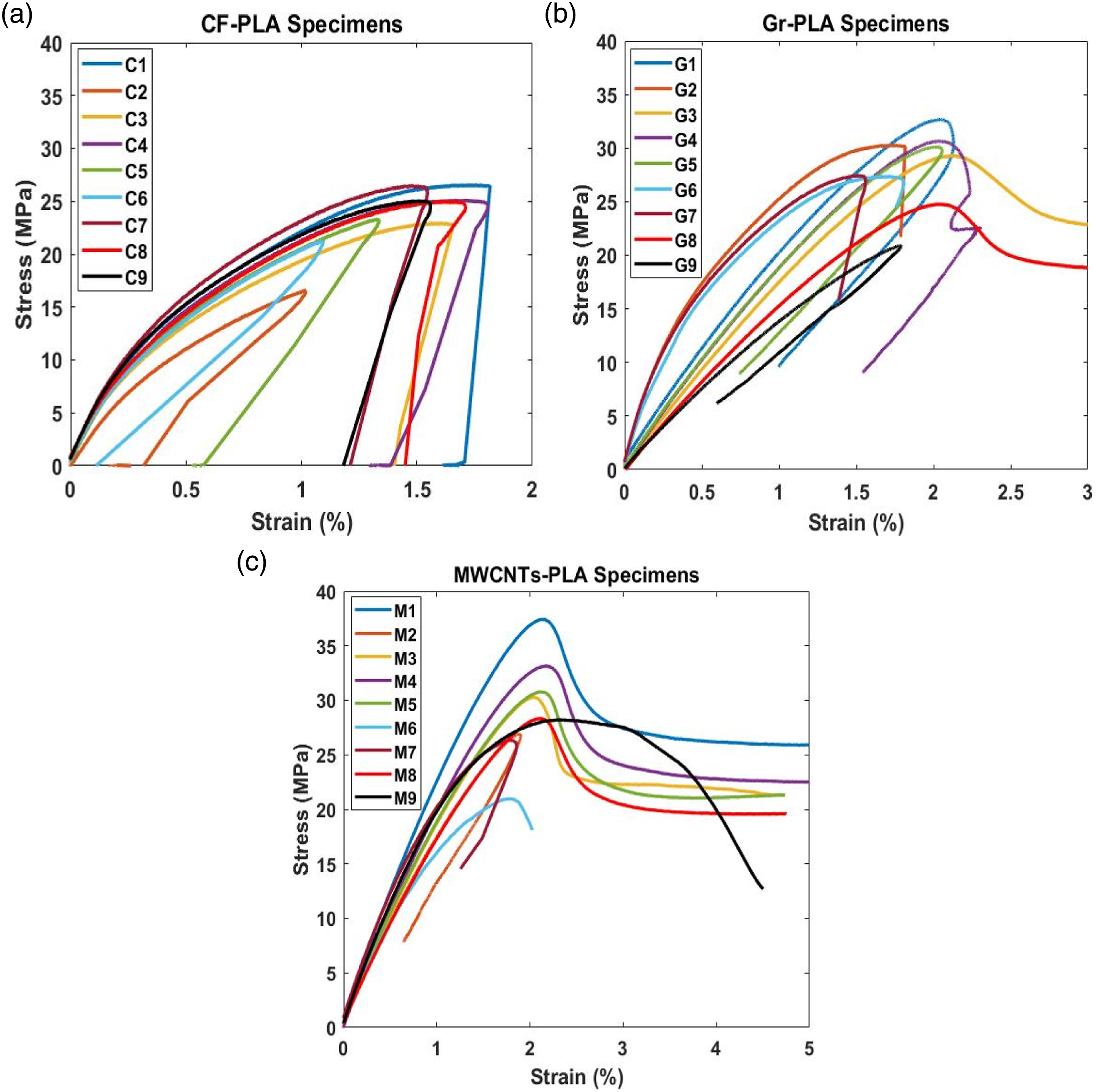
Gr-PLA
At FR = 60 mm/s and RA = 0°, the tensile strength is 20.895 MPa (G9) with 0.606% elongation at break for LH 0.2 mm while for LH 0.1 mm, the tensile strength is enhanced by 40.13% to 29.281 MPa (G3) with 24.833% elongation at break Figure 3(b). The material’s tensile strength is higher at comparatively lower LH. At higher LHs, low percent elongation at break and low stiffness have also been observed. Tensile strength produced for LH 0.15 mm at FR 40 mm/s and RA 0° is 30.131 MPa (G5) with 0.744% elongation at break, which is 21.55% greater than the tensile strength of 24.789 MPa (G8) with 12.11% elongation at break for LH 0.2 mm while maintaining other parameters same, Figure 3(b). Due to weak bonding between the layers, the value of tensile strength falls down.
MWCNTs-PLA
When compared to the tensile strength of 28.226 MPa (M9) with 12.726% elongation at break for LH 0.2 mm (FR = 60 mm/s and RA = 0°), which is enhanced by 0.41% to achieve the tensile strength of 28.343 MPa (M8) with 28.731% elongation at break for LH 0.1 mm (FR = 40 mm/s and RA = 0°), which is 131.74% higher. Tensile strength produced for LH 0.15 mm at FR = 40 mm/s and RA = 0° is 35.779 MPa (M5) with 50.073% elongation at break, which is 26.24% greater than the tensile strength of 28.343 MPa (M8) with 28.731% elongation at break for LH 0.2 mm, Figure 3(c). The interlayer bonding of the FFF-printed Gr-PLA material is weakened when layer thickness is increased, resulting in lower tensile strength.
For fixed value of the process parameters FR and RA, the tensile strength of the specimens falls as the LH increases. The distance between the nozzle and the deposited material rises as the LH increases, resulting in reduced pressure between them. Because the pressure is reduced for the same height, there will be less material deposition and interlayer gaps will widen, resulting in lower interlayer bonding strength and hence lower specimen tensile strength.
Effect of raster angle
The raster angle is another factor that has a significant impact on mechanical characteristics of produced specimens. The inclination of the specimen’s raster with respect to the reference axis is known as the raster angle. In this research, three raster angles (0°,45°,90°) are utilized.
CF-PLA
At LH 0.1 mm and FR 20 mm/s, the tensile strength achieved is 25.089 MPa (C1) with 1.617% elongation at break for RA 0° which is 9.44% higher in comparison with the tensile strength, 22.924 MPa (C2) with 0.168% elongation at break for RA 45°, Figure 3(a). Due to the parallel arrangement of layers, all layers have been laid down parallel to the line of action of the tensile force at 0° RA, and individual layers are capable of sustaining additional load during tensile testing. Because of the perpendicular arrangement of layers to the line of action of the tensile force, the lowest tensile strength achieved is 21.686 MPa (C6) with 0.012% elongation at break at LH 0.15 mm, RA 90°, and FR 60 mm/s, Figure 3(a).
Gr-PLA
For FR 20 mm/s with LH 0.1 mm, the tensile strength, 32.665 MPa (G1) with 0.997% elongation at break with RA 0° because all of the fibres are oriented along the line of action of the tensile force. It is 7.84% higher when RA is changed to 45° and value of tensile strength is reduced to 30.291 MPa (G2) with 0.686% elongation at break, Figure 3(b).
MWCNTs-PLA
At LH 0.1 mm and FR 20 mm/s, the tensile strength achieved is 37.438 MPa (M1) with 15.384% elongation at break for RA 0° which is 4.24% higher in comparison with the tensile strength, 35.916 MPa (M2) with 2.262% elongation at break for RA 45°, Figure 3(c). Due to the parallel arrangement of layers, all layers have been laid down parallel to the line of action of the tensile force at 0° RA, and individual layers are capable of sustaining additional load during tensile testing. At LH 0.15 mm, the lowest tensile strength achieved is 23.995 MPa (M6) with 0.664% elongation at break for RA 90°, and FR 60 mm/s, Figure 3(c). Because of the perpendicular arrangement of layers to the line of action of the tensile force, For a certain FR and LH, the specimen’s maximum strength is at the 0° RA. It’s because there are fewer cavities between the layers at 0° RA, but with other RAs, the number of voids increases, reducing the specimen’s strength. Tensile strength diminishes as the RA increases. Because the shear strength of the neighbouring rasters controls the tensile strength of the specimen, specimens with RA 45° have tensile strength in the range that of RA 0°–90°.
Effect of Feed Rate
FR is a volumetric measurement of the extruded material per second. The pace at which a filament may be extruded is limited by its FR, which is determined by how quickly the filament can physically melt in your hot end. LH is an important factor which has significant impact on the fabricating time and mechanical characteristics of the printed parts. In this experiment three values of FR are utilized viz 20 mm/s, 40 mm/s and 60 mm/s as it influences printing time and mechanical characteristics of FFF-printed parts.
CF-PLA
The tensile strength for FR 60 mm/s is 23.046 MPa (C3) with 1.351% elongation at break at RA 0° and LH 0.1 mm, which is enhanced by 8.86% to the tensile strength of 25.089 MPa (C1) with 1.617% elongation at break for FR 20 mm/s at same RA and LH, Figure 3(a). This is because the voids in the material shrink as the FR grows and the effective cross-sectional area improves. Similarly, at RA 0° and LH 0.15 mm, the tensile strength for FR 40 mm/s, 23.274 MPa (C5), is 7.13% better than the tensile strength for FR 20 mm/s, 24.526 MPa (C4), Figure 3(a).
Gr-PLA
At RA 0° and LH 0.1 mm, the tensile strength for FR 60 mm/s is 29.281 MPa (G3) with 24.833% elongation at break and for FR 20 mm/s 32.665 MPa (G1) with 0.997% elongation at break, Figure 3(b). The value of tensile strength is enhanced by 11.56%. This is because when the FR increases, the voids in the material reduce and the effective cross-sectional area increases. At RA 0° and LH 0.2 mm, tensile strength is 20.895 MPa (G9) with 0.606% elongation at break for FR 60 mm/s and on decreasing the FR, tensile strength is increased by 18.63%–24.789 MPa (G8) with 12.112% elongation at break for FR 40 mm/s, Figure 3(b).
MWCNTs-PLA
At RA 0° and LH 0.15 mm, the tensile strength for FR 40 mm/s, 35.779 MPa (M5) with 50.073% elongation at break, is 1.06% higher than the tensile strength for FR 20 mm/s, 36.159 MPa (M4) with 28.545% elongation at break, Figure 3(c). At RA 0° and LH 0.2 mm, tensile strength, 28.343 MPa (M8) with 28.731% elongation at break for FR 40 mm/s is higher on comparison with the tensile strength of 28.226 MPa (M9) with 12.726% elongation at break for FR 60 mm/s, Figure 3(c).
The tensile strength decreases on increasing FR while maintaining the raster angle and LH constant. Increases in FR or LH, or both, can reduce printing time, however raising LH reduces tensile strength by a higher amount, therefore FR may be a preferable option for printing faster with a little drop in tensile strength.
Fractography
For a better understanding of the fracture mechanism, FESEM (Field Emission Scanning Electron Microscope) was utilised to analyse the fracture surfaces of the tensile specimens.
CF-PLA
Figure 4 and Figure 5 illustrate the effect of RA on the fracture surface of the tensile specimen for CF-PLA specimens. For specimen C1, the failure is mostly due to raster failure because rasters are oriented parallel to the loading direction, resulting in the highest tensile strength for a CF-PLA tensile specimen. The maximum tensile strength, 25.089 MPa, is exhibited for sample C1 with 1.617% elongation at break for RA 0°, FR 20 mm/s and LH 0.1 mm, also depicting a combination of brittle and ductile failure. Fracture surface of the tensile specimen C1 at RA 0°, FR 20 mm/s and LH 0.1 mm for CF-PLA. Fracture surface of the tensile specimen C2 at RA 45°, FR 20 mm/s and LH 0.1 mm for CF-PLA.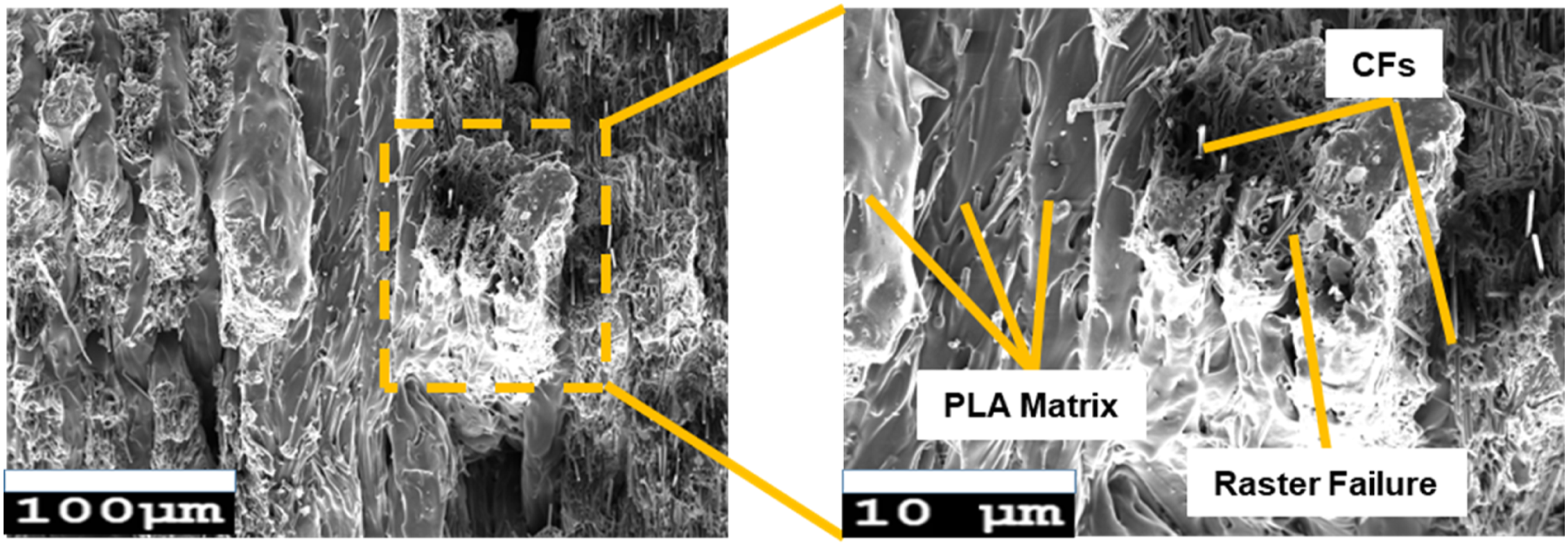
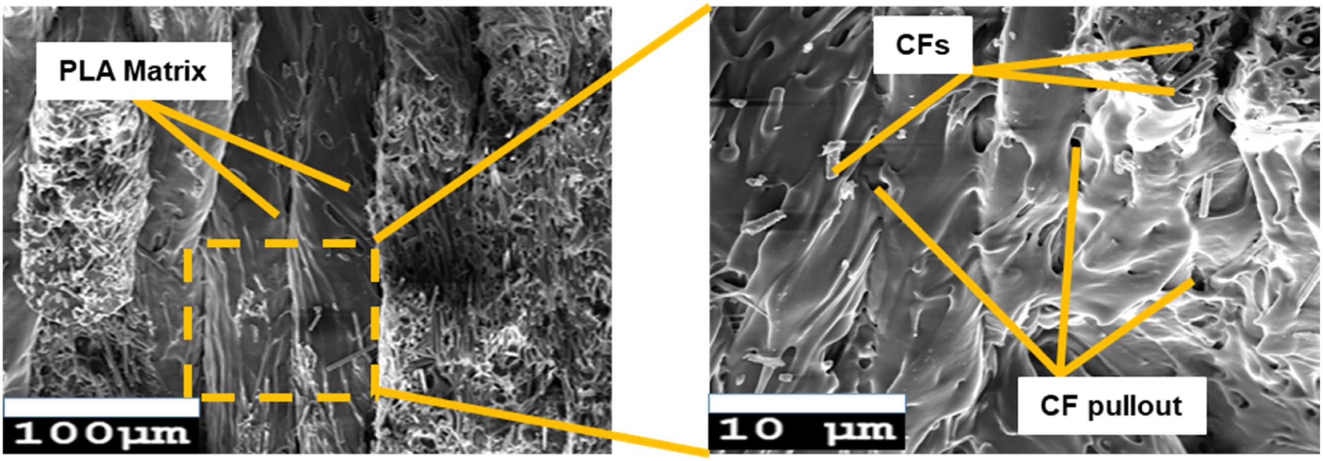
Similarly, for specimen C2, the failure is mostly due to breaking and pulling of CFs, which results in brittle failure and comparatively low tensile strength (22.924 MPa with 0.168% elongation at break for RA 45°, FR 20 mm/s and LH 0.1 mm) while maintaining other process parameters constant.
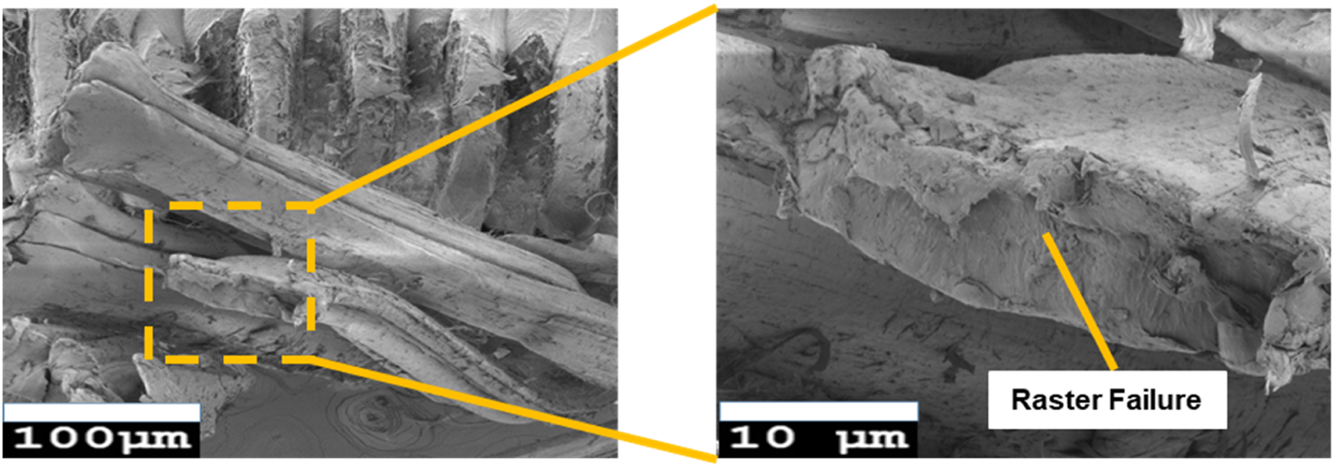
Figure 6 and Figure 7 illustrate the effects of RA and LH on failure modes for CF-PLA specimens. For specimen C3, the failure is due to breaking of CFs and failure of individual rasters because raster orientation matches with the line of action of the applied tensile force, resulting in brittle failure, which results in the tensile strength of 23.046 MPa with 1.131% elongation at break for RA 0°, FR 60 mm/s and LH 0.1 mm. Fracture surface of the tensile specimen C3 at RA 0°, FR 60 mm/s and LH 0.1 mm for CF-PLA. Fracture surface of the tensile specimen C6 at RA 90°, FR 60 mm/s and LH 0.15 mm for CF-PLA.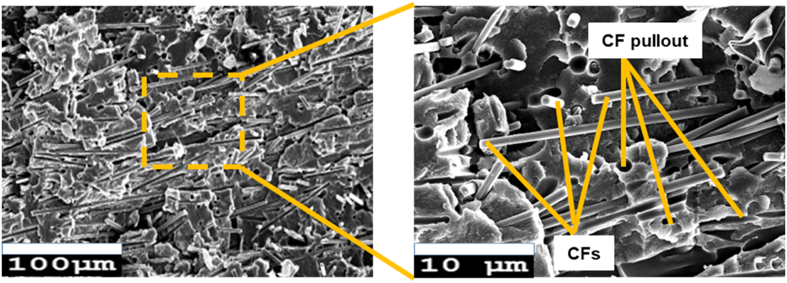
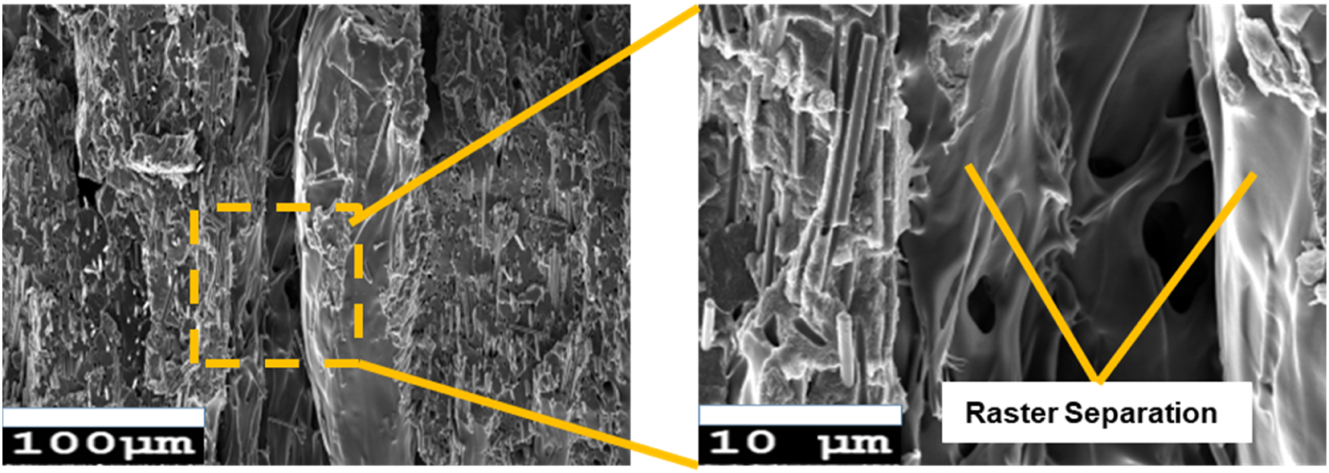
Also, for specimen C6, fracture mode is also detected as a result of weak raster to raster bonding, which results in raster separation and brittle failure of the specimen because of the perpendicular alignment of the raster with respect to the line of action of the tensile force. The explained failure mode results in a tensile strength of 21.686 MPa with 0.012% elongation at break for RA 90°, FR 60 m
Gr-PLA
For Gr-PLA specimens, the impact of RA on the fracture surface of the tensile specimen is depicted in Figure 8 and Figure 9. The SEM analysis of specimen G1 depicts delamination and separation of the rasters, which defines the failure mode of the specimen. The specimen G1 shows brittle failure and less % elongation at break because of the parallel alignment of the raster in the direction of the tensile force, thus exhibiting the maximum tensile strength of 32.665 MPa with 0.997% elongation at break for RA 0°, FR 20 mm/s and LH 0.1 mm. Fracture surface of the tensile specimen G1 at RA 0°, FR 20 mm/s and LH 0.1 mm for Gr-PLA. Fracture surface of the tensile specimen G2 at RA 45°, FR 20 mm/s and LH 0.1 mm for Gr-PLA.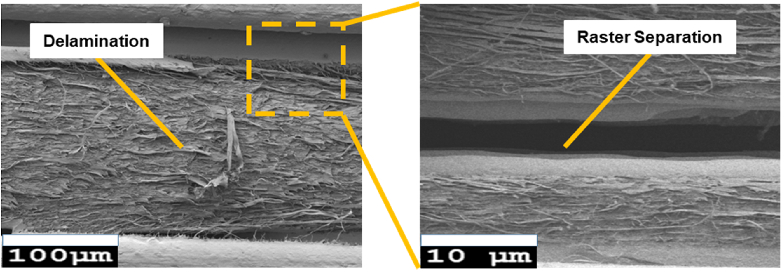
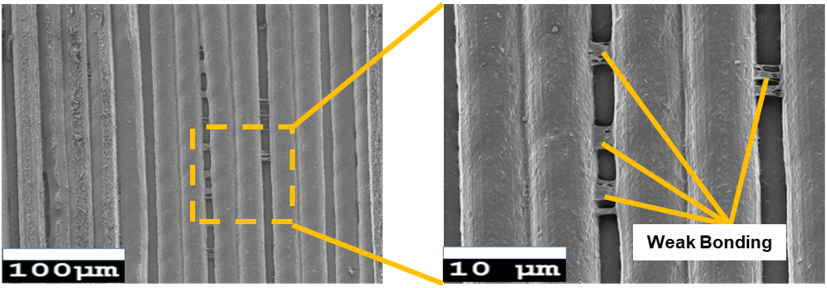
In the same way, specimen G2 exhibits maximal tensile strength but less percent elongation at break because of brittle failure. The failure is mostly due to weak bonding between the rasters, resulting in comparatively low tensile strength for the tensile specimen with RA 0° while maintaining other process parameters constant. It has a tensile strength of 30.291 MPa with 0.686% elongation at break for RA 45°, FR 20 mm/s and LH 0.1 mm.
For Gr-PLA specimens, the impact of RA and LH on failure modes is depicted in Figure 10 and Figure 11. For specimen G3, the failure is mostly due to raster-to-raster bonding failure (because of the higher FR of 60 mm/s), which reduces the tensile strength of the specimen to 29.281 MPa with 24.833% elongation at break for RA 0°, FR 60 mm/s and LH 0.1 mm. The specimen shows ductile failure because it has maximum % elongation at break during tensile testing. Fracture surface of the tensile specimen G3 at RA 0°, FR 60 mm/s and LH 0.1 mm for Gr-PLA. Fracture surface of the tensile specimen G6 at RA 90°, FR 60 mm/s and LH 0.15 mm for Gr-PLA.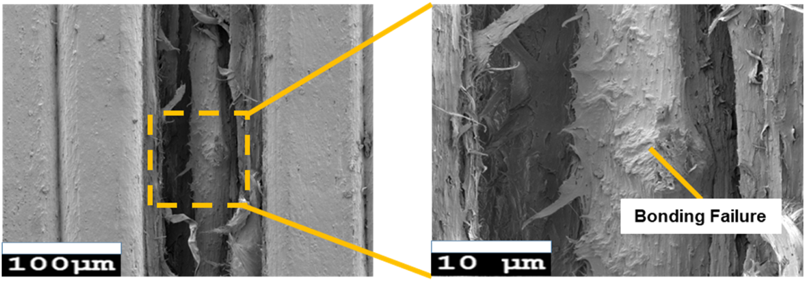
Also, for specimen G6, fracture is also detected as a result of individual raster breaking due to a substantial degree of pulling and necking of individual rasters. Because each fibre bears the force and the consequence of raster-to-raster bonding is minimised, the specimen has a higher rigidity because of the perpendicular alignment of the raster with respect to the line of action of the tensile force. It flaunts a tensile strength of 27.374 MPa with 1.18% elongation at break for RA 90°, FR 60 mm/s and LH 0.15 mm.
MWCNTs-PLA
Figure 12 and Figure 13 demonstrate how RA affects the tensile specimen’s fracture surface for MWCNTs-PLA specimens. For MWCNTs-PLA, specimen M1 depicts ductile failure of the individual rasters after separation because rasters are oriented parallel to the loading direction and results in the highest tensile strength of 37.438 MPa with 15.384% elongation at break for RA 0°, FR 20 mm/s and LH 0.1 mm. It shows ductile failure of the individual rasters after separation because rasters are oriented parallel to the loading direction, depicting the highest tensile strength for MWCNTs-PLA tensile specimen. Fracture surface of the tensile specimen M1 at RA 0°, FR 20 mm/s and LH 0.1 mm for MWCNTs-PLA. Fracture surface of the tensile specimen M2 at RA 45°, FR 20 mm/s and LH 0.1 mm for MWCNTs-PLA.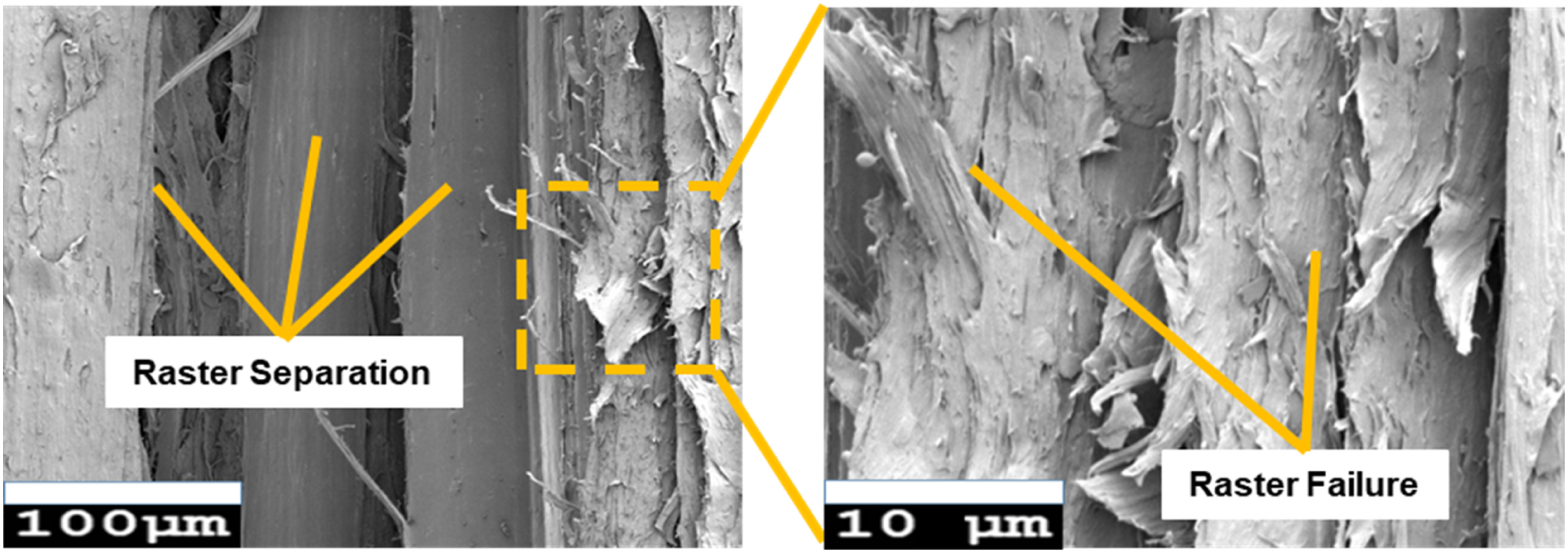
In a similar way, for specimen M2, the presence of voids in the specimen lowers its tensile strength, leading to brittle failure and with a lower tensile strength of 35.916 MPa (M2) with 0.652% elongation at break for RA 45°, FR 20 mm/s and LH 0.1 mm.
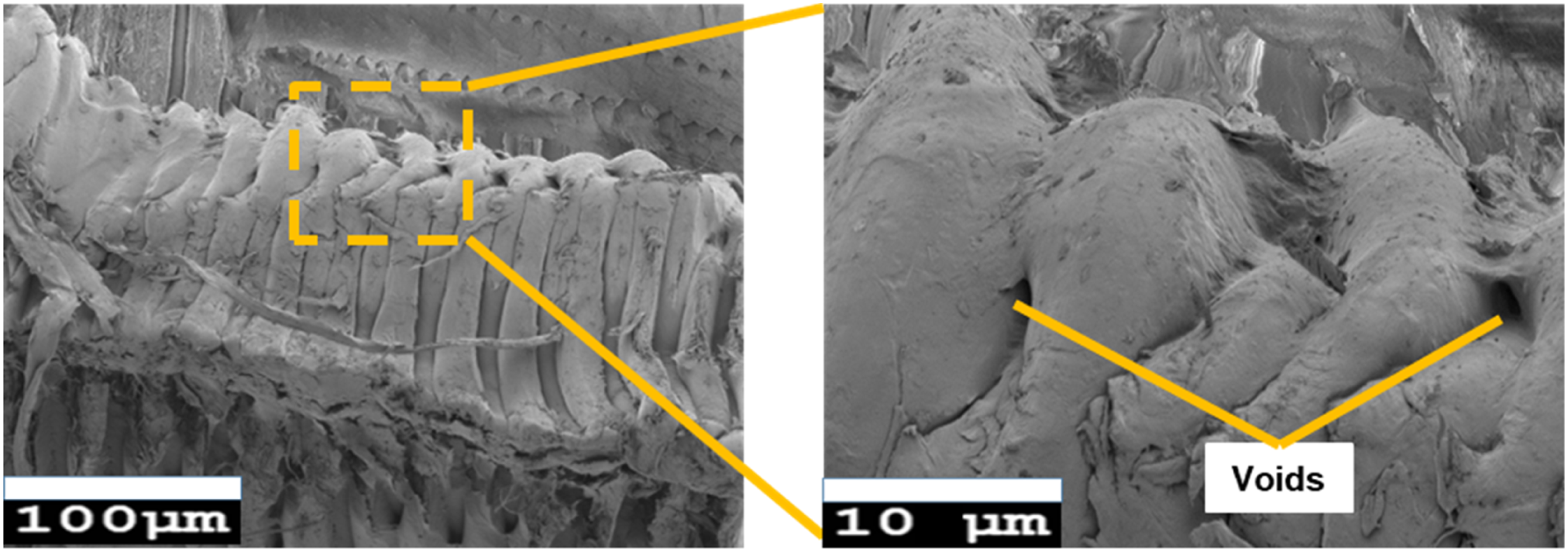
The influence of FR and LH on failure modes is shown for MWCNTs-PLA specimens in Figure 14 and Figure 15. For specimen M3, ductile failure of the individual rasters due to weak bonding between them at the higher FR of 60 mm/s results in a tensile strength of 35.284 MPa with 11.336% elongation at break for RA 0°, FR 60 mm/s and LH 0.1 mm. Fracture surface of the tensile specimen M3 at RA 0°, FR 60 mm/s and LH 0.1 mm for MWCNTs-PLA. Fracture surface of the tensile specimen M5 at RA 0°, FR 40 mm/s and LH 0.15 mm for MWCNTs-PLA.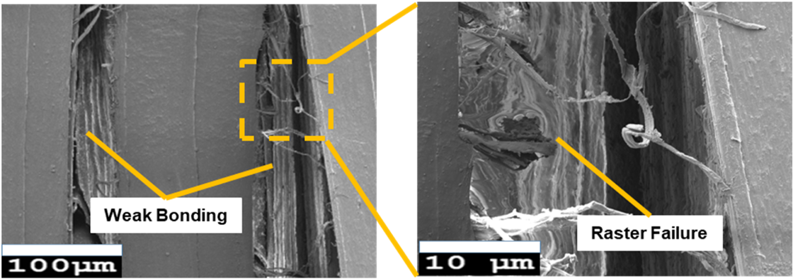
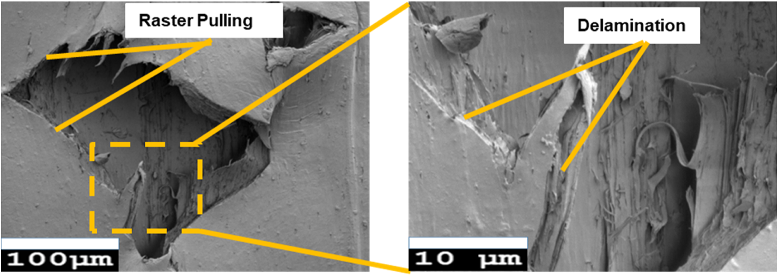
For specimen M5, delamination and pulling of the rasters define the failure mode of the specimen while resulting in a maximum tensile strength of 30.779 MPa (M5) with 50.073% elongation at break for RA 0°, FR 40 mm/s and LH 0.15 mm. The specimen depicts brittle failure and it has a maximum % elongation at break for MWCNTs-PLA with the parallel alignment of the raster in the direction of the line of action of the tensile force.
At RA 0°, FR 20 mm/s and LH 0.1 mm, CF-PLA shows its maximum tensile strength, 25.089 MPa (C1) with maximum elongation at break 1.617%, Gr-PLA exhibited its maximum tensile strength of 32.665 MPa (G1) with 0.997% elongation at break but MWCNTs depicts overall maximum tensile strength, 37.438 MPa (M1) with 15.384% elongation at break which is 49.22% and 14.61% higher in comparison with CF-PLA and Gr-PLA, respectively. Higher extrusion pressure at low LH aids layer formation of a rapid and intimate bond, resulting in increased bond strength and tensile strength. From the micrographs, Figure 16, it is clear that for CF-PLA, all CFs break and pull out of the PLA matrix, resulting in low tensile strength in comparison to the other fabricating materials. For Gr-PLA, raster to raster bonding is weaker than individual raster and delamination, resulting in lower tensile strength. For MWCNTs, the main cause of specimen failure during testing is detected as a result of an individual raster breaking due to a substantial degree of pulling and necking of individual rasters. Because each fibre bears the force and the consequence of raster-to-raster bonding is minimised, the specimen has a higher rigidity, resulting in a higher tensile strength. Fracture surface of the tensile specimen at RA 0°, FR 20 mm/s and LH 0.1 mm for different fabricating material (a) CF-PLA, (b) Gr-PLA, (c) MWCNTs-PLA.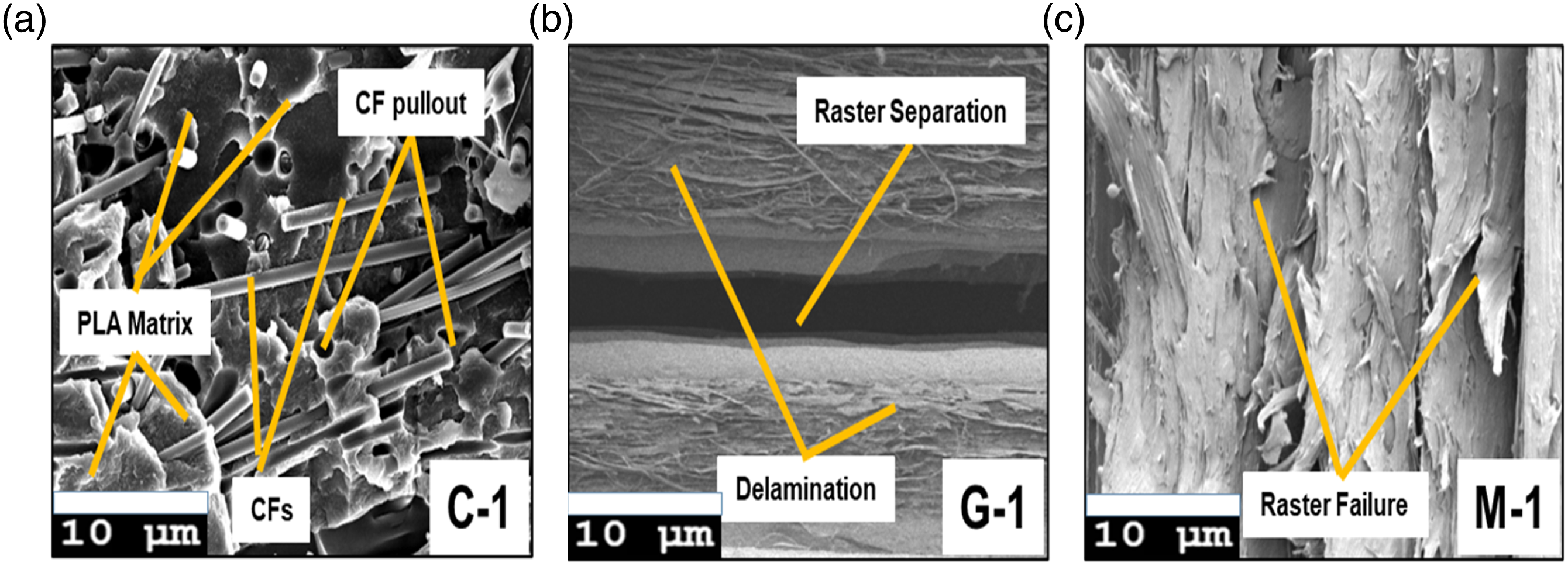
Figure 17 illustrates the different type of voids observed in the fabricated parts using FFF. There are periodic voids due to the raster spreading which are known as Inter-void. 40,41 It is the result of nozzle shape and fused material flow characteristics. On the other hand, interfacial void is occurred due to inadequate bond quality between the rasters of the adjacent layers. 40,41 These voids affect the tensile properties of the fabricated specimen and can be minimised by selecting the proper combination of the FFF process parameters. Different Types of voids detected in FFF-printed parts (a) Schematic diagram, (b) SEM image.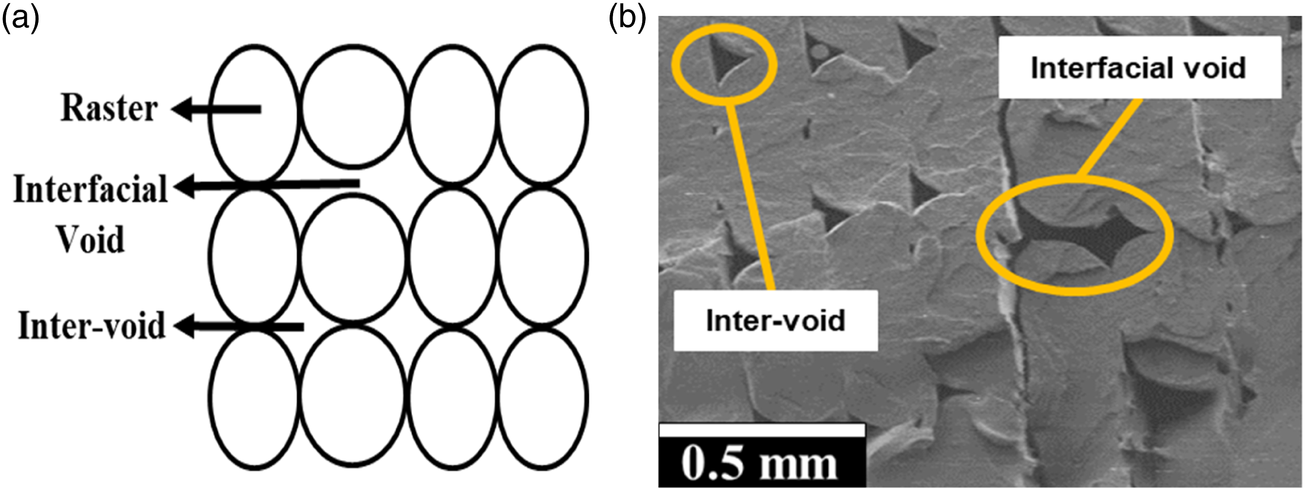
Analysis of Variance (ANOVA)
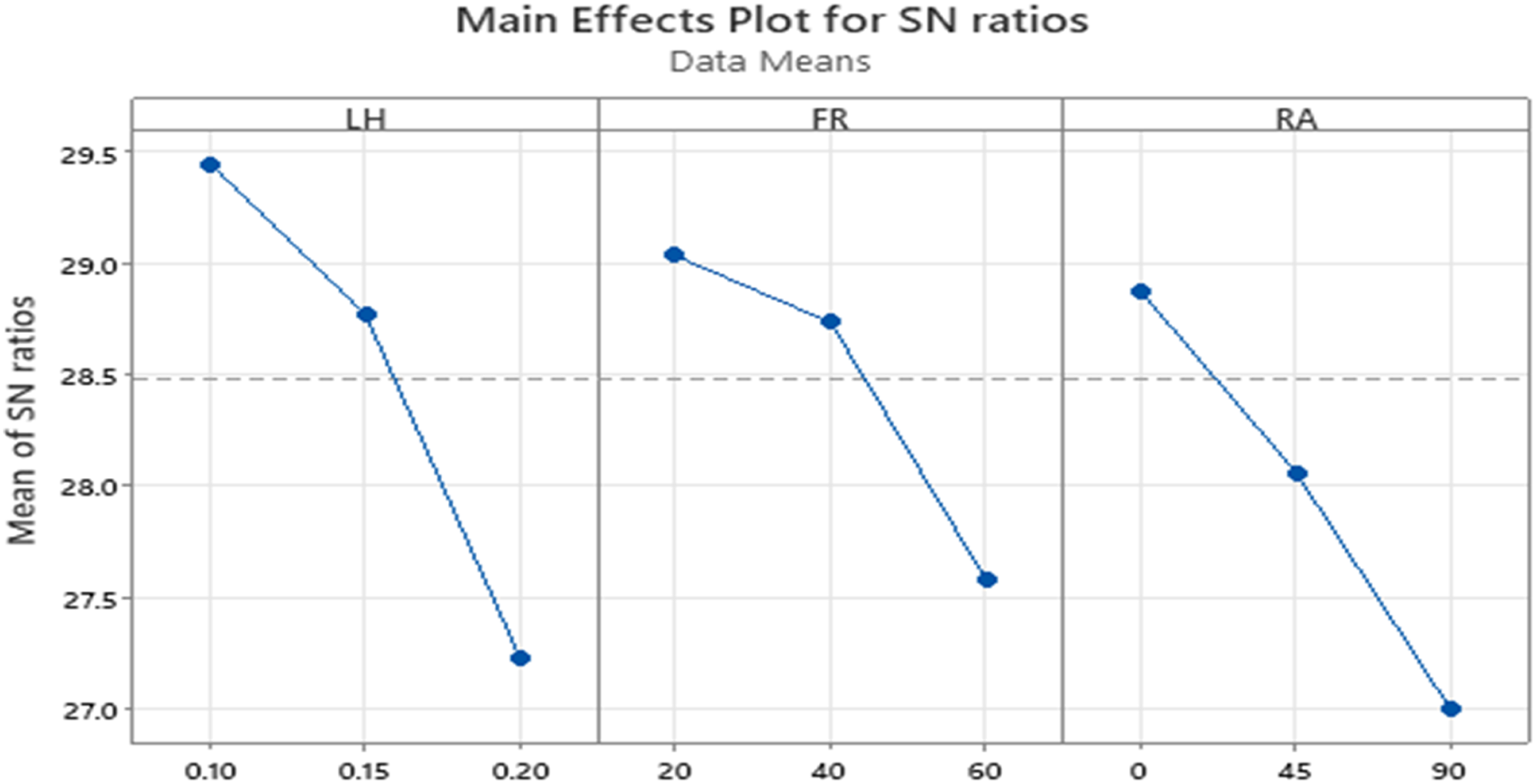
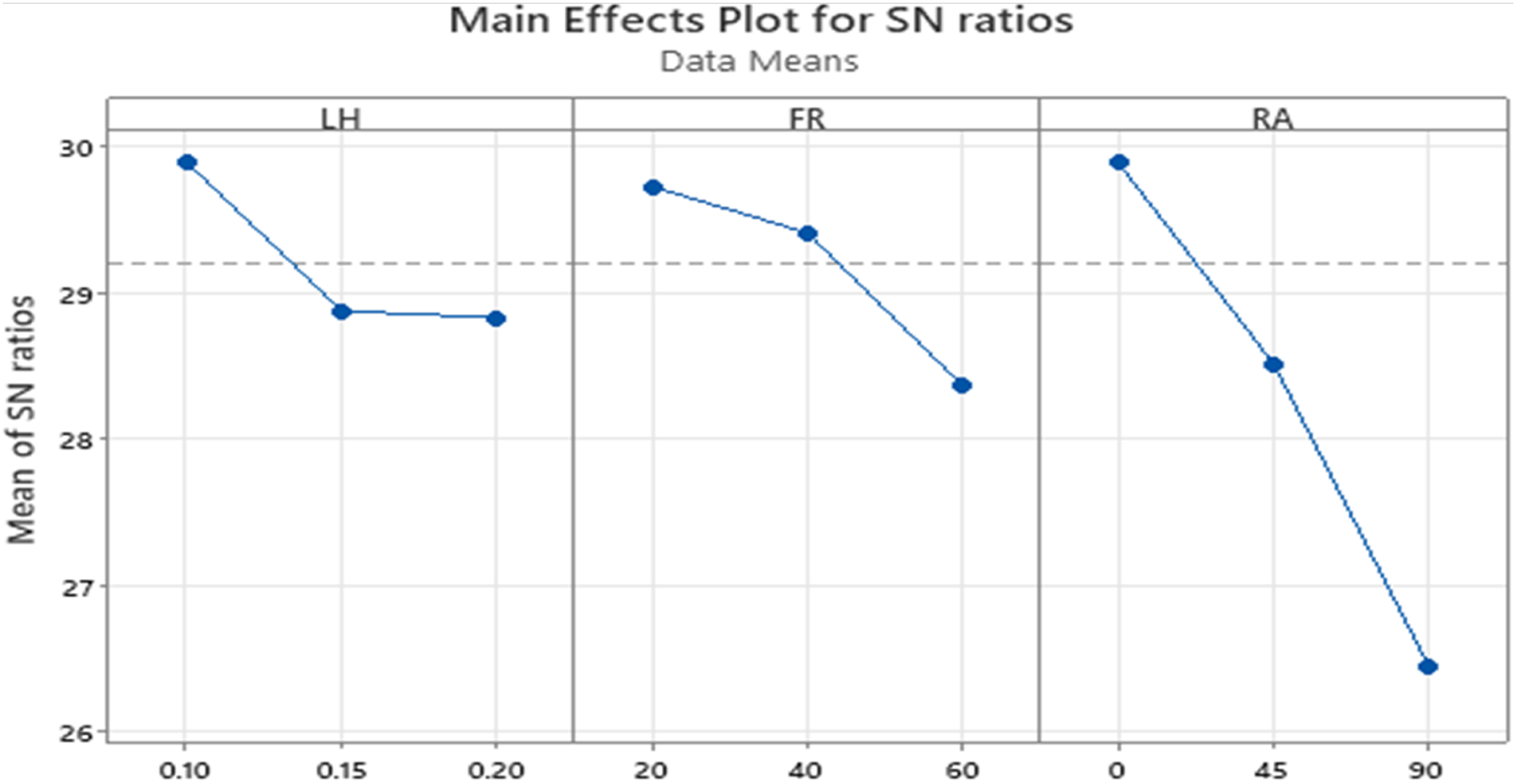
ANOVA study of the process parameters, namely LH, FR, and RA, with three levels each over the response factor, tensile strength of CF-PLA using Taguchi’s L9 array DOE, results in a greater is better main effects plot for signal to noise ratios (SN ratios), as shown in Figure 18, Figure 19 and Figure 20 for CF-PLA, Gr-PLA and MWCNTs-PLA, respectively. The experimental outcomes are investigated using the MINITAB 21 programme. S/N ratios plots of the main effects of the process parameters on the tensile strength for CF-PLA. S/N ratios plots of the main effects of the process parameters on the tensile strength for Gr-PLA. S/N ratios plots of the main effects of the process parameters on the tensile strength for MWCNTs-PLA.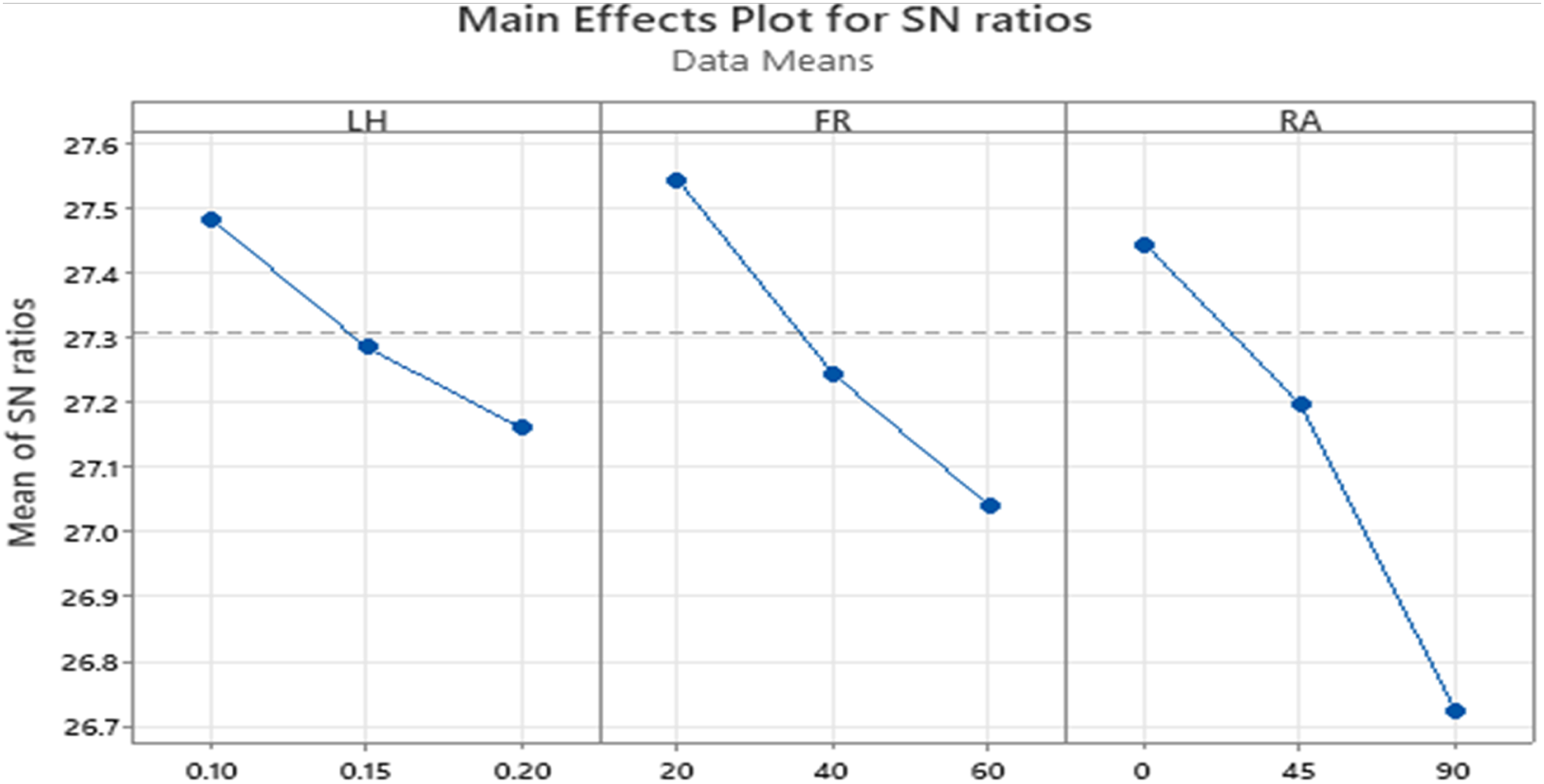
CF-PLA
Analysis of Variance for CF-PLA Tensile strength.
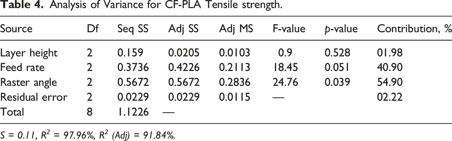
S = 0.11, R 2 = 97.96%, R 2 (Adj) = 91.84%.
Gr-PLA
Analysis of Variance for Gr-PLA Tensile strength.
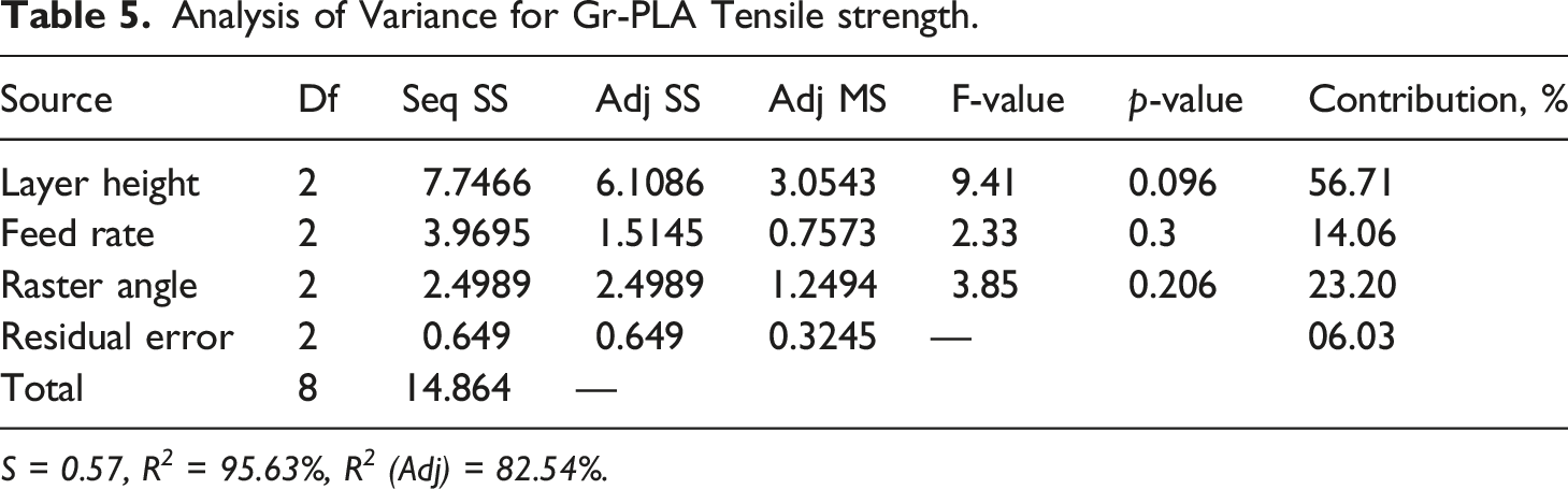
S = 0.57, R 2 = 95.63%, R 2 (Adj) = 82.54%.
MWCNTs-PLA
Analysis of Variance for MWCNTs-PLA Tensile strength.
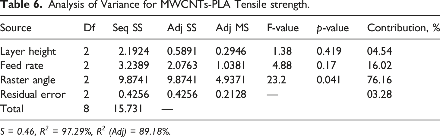
S = 0.46, R 2 = 97.29%, R 2 (Adj) = 89.18%.
The impact of variation in process parameter viz RA, LH and FR to selected target factor viz tensile strength is different for individual fabricating material. When analysing the impact of process variables on tensile strength, LH has maximum contribution of 56.71% followed by RA and FR for Gr-PLA but for CF-PLA and MWCNTs-PLA, RA has maximum contribution of 54.90% and 76.16%, respectively, followed by FR and LH. So based on fabricating material, contribution of different parameters varies, it may be due to the variation and distribution of reinforcing material in the PLA matrix.
The maximum tensile strength achieved is 37.438 MPa at LH 0.1 mm, FR 20 mm/s and RA 0° for the MWCNTs-PLA specimen, which is higher than the results reported by Mensah et al. 42 of 35 MPa for pure PLA. The maximal elastic modulus for the CF-PLA specimen is 4471 MPa at LH 0.1 mm, FR 20 mm/s, and RA 0°, which is 327.44% greater than the elastic modulus of 1046 MPa for pure PLA reported by Mensah et al. 42 The higher the elastic modulus of the composite material, it is more resistant to deformation within the elastic range.
Conclusion
The purpose of this study was to understand and analyse the mechanical characteristics of FFF-printed CF-PLA, Gr-PLA, and MWCNTs-PLA specimens with respect to alterations in the process parameters - RA, FR, and LH. This work outlines the preferred material-parameter combinations for higher strength and ductility. The results indicate that as the LH decreases, the specimens' tensile strength increases. When LH is changed from 0.15 mm to 0.1 mm at FR 20 mm/s and RA 0°, the tensile strength of CF-PLA increases by 2.29%, for Gr-PLA by 6.52%, and 3.54% for MWCNTs-PLA. At LH 0.1 mm, and FR 20 mm/s when RA reduced from 45° to 0°, tensile strength is increased by 9.44% for CF-PLA, 7.84% for Gr-PLA, and 4.24% for MWCNTs-PLA. With the reduction of RA, the specimens' tensile strength improves.
The tensile strength also increases on decreasing FR, it is enhanced by 8.86% for CF-PLA, 11.56% for Gr-PLA and 6.10% for MWCNTs-PLA when LH 0.1 mm, RA 0° and FR decreases from 60 mm/s to 20 mm/s. At LH 0.1 mm, RA 0° and FR 20 mm/s, as a result of individual raster breaking due to a substantial degree of pulling and necking, MWCNTs exhibits overall maximum tensile strength, 37.438 MPa with 15.384% elongation at break which is 49.22% and 14.61% higher respectively, in comparison with CF-PLA, 25.089 MPa with 1.617% elongation at break, and Gr-PLA, 32.665 MPa with 0.997% elongation at break.
The effect of a change in a process parameter on the target factor varies depending on the fabricating material. LH has the highest contribution of 56.71% for Gr-PLA, but RA has the highest contribution of 54.90% and 76.16% for CF-PLA and MWCNTs-PLA, respectively, with all R2 values greater than 95%. At LH 0.15 mm, RA 0° and FR 40 mm/s, MWCNTs exhibits overall maximum elongation at break 50.07% which is 2996.66% and 101.64% higher respectively, in comparison with individual highest elongation at break 1.167% at LH 0.1 mm, RA 0°, FR 20 mm/s and 24.83% at LH 0.1 mm, RA 0° and FR 60 mm/s, for CF-PLA and Gr-PLA, respectively.
Footnotes
Acknowledgements
The authors acknowledge the help from ACMS, IIT Kanpur, India for allowing to perform tensile testing. Support from FESEM lab, Department of Chemistry, DEI is highly appreciated for fractography analysis. We are also thankful to the grant received from AICTE (file no. 8–88/FDC/RPS (POLICY-1)/2019-20).
Declaration of conflicting interests
The author(s) declared no potential conflicts of interest with respect to the research, authorship, and/or publication of this article.
Funding
The author(s) received no financial support for the research, authorship, and/or publication of this article.