
Abstract
The helical spring is one of the most used components in mechanisms but there is little research on the application of 3D printing, also called Additive Manufacturing, to springs. Therefore, the objective of this paper is to derive a model for the stiffness of 3D printed springs. The equation assumes that springs are made of orthotropic material and with a rectangular wire cross-section, that is, die springs. A second version of the equation has also been postulated that accounts for the misalignment of the deposited tracks with respect to the direction of the coils due to the coil pitch. The two models are compared to various springs printed with PLA and ULTEM 9085 and are found to accurately predict the stiffness of real, 3D printed springs. These equations allow the design and manufacturing of helical die springs for applications with few load cycles and that require chemical and radiation resistance, such as in space. The equations are also the first step in the development of models for new kinds of springs, such as linear conical springs or hollow wire die springs.
Keywords
Introduction
3D printing, or Additive Manufacturing (AM), is a manufacturing technology where successive layers of materials are deposited one on top of another to manufacture parts. 1 It is used to make parts quickly while maintaining material waste to a minimum.2,3 The AM process allows the creation of parts with complex geometries that are hard if not impossible to manufacture by conventional means, for example mechanisms that don’t require assembly. 4 AM has a very high degree of design freedom but is limited by the lack of modelling that is still present in many applications. 5
One of the areas that require exploring in view of modelling is 3D printed springs. Springs are a widely used type of mechanical device used to store and release mechanical energy. 6 This paper is concerned with cylindrical helical springs, one of the most common types, of which there are two general varieties: tension and compression. There exists an equation for calculating the spring stiffness from the material and spring properties but it cannot be used with 3D printed springs since materials produced via AM are strongly anisotropic for three reasons.7,8 First, during printing the plastic is deposited in tracks, thus responding to stress differently depending on the direction that the stress is applied. Secondly, inter-layer bonding is stronger compared to bonding between tracks. Finally gaps and porosities can form between tracks, creating areas where the stress response is dissimilar from that of the surrounding material. 9
Therefore, the objective of this paper is to derive an equation for modelling the stiffness of 3D printed springs. The assumption is that springs behave elastically and, although the experimental data used compression springs, the conclusions are valid also for tension springs. Two equations have been derived starting from the assumption that the springs are made of orthotropic material and that they have a rectangular wire cross-section. The first step involves deriving an expression for the torsional rigidity of an orthotropic, rectangular beam. Then the energy stored by a beam undergoing torsion, with length equal to an uncoiled spring, is equated to the energy stored by a spring. Solving for the stiffness results in the first of the two equations that model the stiffness of a 3D printed spring. The second equation comes from rotating the shear moduli by an angle equal to that formed by the spring’s coils. Once both equations are derived, the predicted stiffness values are compared to experimentally measured ones. Two materials are used to print the springs. The bulk are manufactured with Polylactic Acid or Poylactide (PLA) and Fused Filament Fabrication (FFF). A comparison is made with ULTEM 9085 printed with Fused Deposition Modelling (FDM). This high performance thermopolymer is chosen for its strong mechanical properties (www.stratasys.com/materials/search/ultem9085) and the fact that it has been used to manufacture functional parts for aerospace applications.10,11
The paper is structured in the following manner; first the mathematical problem is stated in the section titled Mathematical Problem, then the equation for the stiffness of 3D printed springs is derived (in sections Solving for the stress function and Derivation of the equation for k). The section called Experimental Data discusses the measurement of the shear moduli of the material, and the testing of several printed springs for comparison with the model’s predictions. Finally the reliability of the equations is tested by comparing the calculated stiffness constants to the measured ones in the section titled Comparison of Experimental and Calculated Data.
3D printed springs in the literature
There is little research that applies AM to mechanical springs. Saleh and Ragab 12 studied the effects of geometry on the shear modulus of helical springs manufactured with Ti-6Al-4V via Selective Laser Melting (SLM). They printed various springs with different pitches to verify if changes in the geometry of the material affect the shear modulus. The springs show no signs of supports, likely due to their small size (42.04 mm in length and 22.14 mm in diameter), which could be a problem with bigger springs.
He et al. 13 created an interactive tool that allows users to create and control 3D printed deformable objects with embedded springs and joints. First they tested tensile samples made of PLA to obtain the material properties. Like Saleh and Ragab, they calculated the shear modulus of the material and verified that it gave them good results when varying the spring parameters.
Hoa 14 used 4D printing to manufacture and test curved leaf springs using flat moulds. The springs were manufactured in a flat mould and would acquire their curvature after the fibre laying process was complete. This is different to normal composite springs, which are manufactured in curved moulds, examples of which are leaf springs for auto-mobiles and in prostheses. The results showed that it was possible to use 4D printing to manufacture composite springs with stiffness constants and strengths comparable to composite springs that were manufactured with conventional methods.
There is also literature on springs manufactured with composite materials: optimization of spring performance,15–17 substitution of metal springs with composite ones,18–20 tubular helical spring whose structure is made from multiple laminae of composite material, 21 and optimizing design variables of carbon-fibre reinforced epoxy composite coil springs. 22 There is also a lot of literature on springs with unusual shapes 23 and that use shape memory materials 24 but since here the material is modelled isotropically, the research cannot be used with AM.
The work by Saleh and Ragab, He et al. and Hoa were the only instances of published literature that could be found that made use of AM to produce springs. Composite materials are much closer to materials produced by AM but there are two issues when it comes to applying the techniques for composites to 3D printing. First, in the majority of literature, the materials are modelled as isotropic12,13,15–21 or transversely isotropic,22,25 which is not true of AM, where materials are highly anisotropic.26–28
The second issue is that, with some exceptions,17,20 the research employs a circular wire cross-section 29 due to ease of manufacturing and in calculations. There are two reasons for this not being ideal for AM. First, early testing showed that printing a helical spring with a circular cross-section produced coils that were tear-shaped instead of round, which could compromise the functioning of the spring. A rectangular wire cross-section instead printed with no visible deformations. Second, since 3D printed materials are anisotropic and not radially orthotropic, warping will be present even if the cross-section of the shaft is circular,30–32 unlike with isotropic materials.
Due to the sparsity of published literature on the subject, the conclusion can be made that there is a definite research gap when it comes to the application of AM to springs. Simple material models are proposed in the literature and no detailed study has been made on springs manufactured via AM. Therefore this paper develops a model to predict the stiffness of 3D printed springs and compares the theoretical results to experimental data. The model developed allows easier manufacturing of die springs via AM and is the first step to developing models for springs with unusual shapes that take advantage of AM’s design freedom, such as springs with non-prismatic wires, hollow wire die springs, or linear conical springs. When combined with the advancements that are being made in the field of fibre reinforced thermoplastic composites printed with FFF, 33 the model would allow custom composite springs to be designed and manufactured quickly and easily. The model developed in this research is the first step in the development of design tools such as currently exist for conventional springs. 34
Mathematical problem
The assumption in this paper is that the displacements and rotations are small enough that the spring behaves elastically. Springs obey Hooke’s law
Cross-section of a spring with rectangular wire cross-section showing the spring parameters.
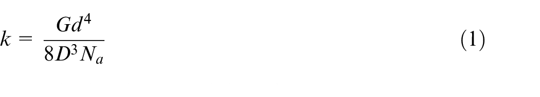
Here G is the shear modulus of the material, D is the diameter of the coils, d is the diameter of the wire, and
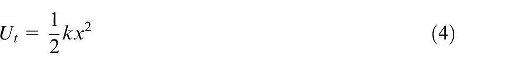
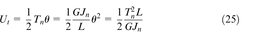
The energy stored by a spring can be written in two ways. From Hooke’s law we have that
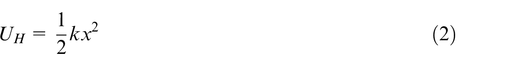
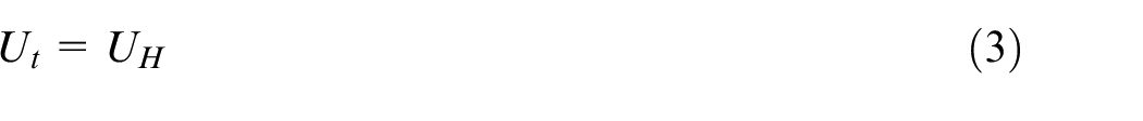
but the spring can also be considered to be a shaft undergoing torsion and therefore gaining torsional energy
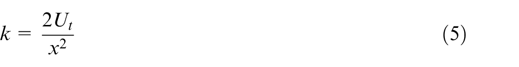
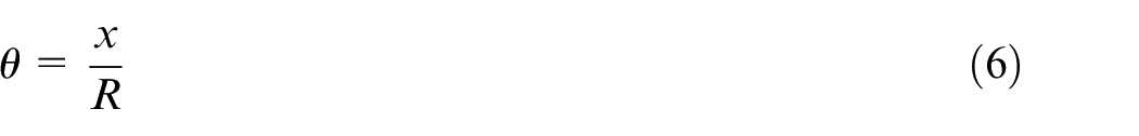
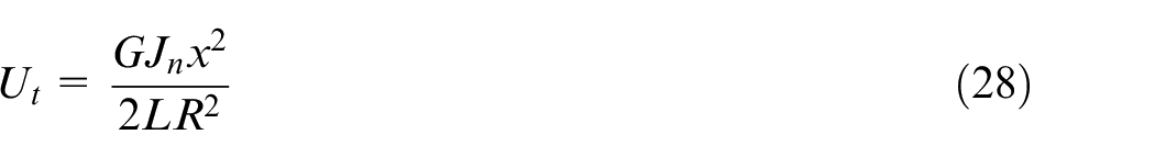
In equation (5) the spring constant is inversely proportional to the square of x, which would mean that k is non linear. This is wrong because within the elastic limit k is a constant for cylindrical helical springs, therefore it is necessary to find a relationship between x and the amount of torsion each part of the spring undergoes. The spring can be considered to be composed of many identical elements as shown in Figure 2, which lie a distance of

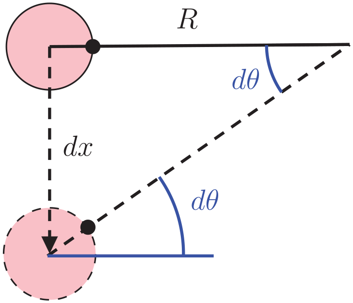
Distance that coils move when a spring is stretched.
so equation (5) becomes
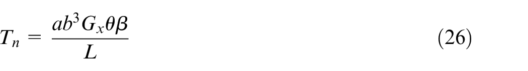
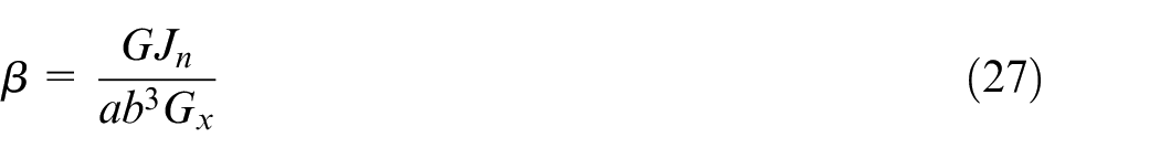
Now an expression for
(i) The material is orthotropic;
(ii) The cross-section is rectangular.
The basic idea is to find a form of
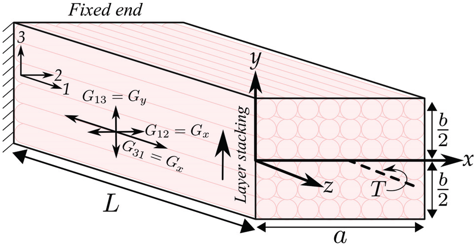
Rectangular prismatic shaft under torsion at one end. The material directions and shear moduli are also shown.
If the cross-section of the beam is regular, an analytical solution can typically be found, otherwise numerical solutions are needed. 38 This is relevant when dealing with 3D printed springs because new types of springs can be made with novel, irregular cross-sections. Fortunately a rectangular cross-section is regular so an analytical solution is possible. A rectangular cross-section produces Dirichlet (or first-type) Boundary Condition (BC)s due to the traction free BCs, where the solution’s boundary values are specified. Therefore, Prandtl’s stress function is more appropriate. 39
Mono-directional in-fill
To simplify the problem an in-fill was chosen for the springs that was constant along the z-axis in Figure 3. Figure 4(a) shows a top-down view of two rings with different in-fills. The commonly used 0/90, or
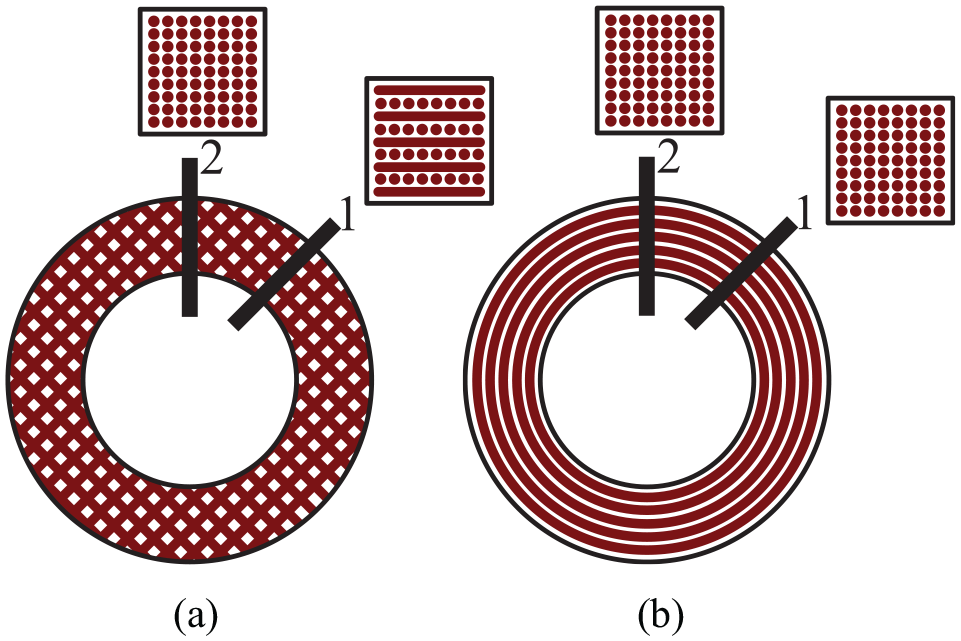
Top-down view of rings showing the differences between in-fills: (a) the cross-section of the
To produce the mono-directional in-fill, the slicing programme is set to produce a high number of contours. The in-fill is more consistent than the
Solving for the stress function
According to Saint-Venant’s torsion theory the displacements are 40


where u, v and w are displacements and
where
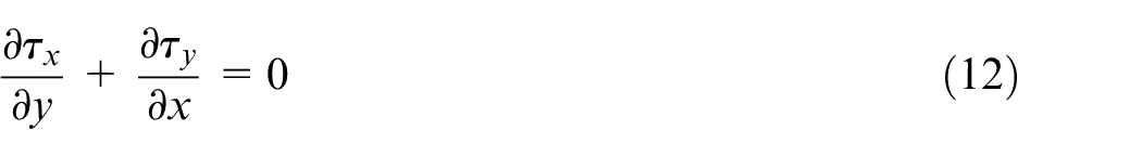
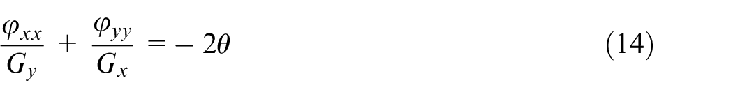
therefore the governing Partial Differential Equation (PDE) to be solved is
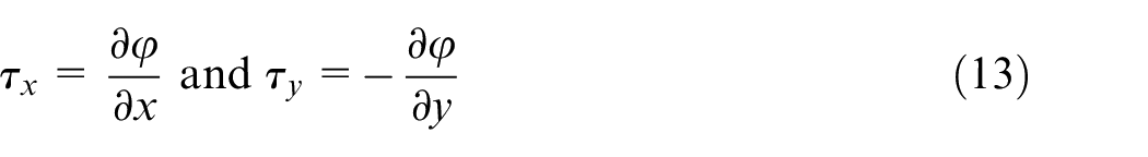
and the traction free BCs are satisfied if
or in other words
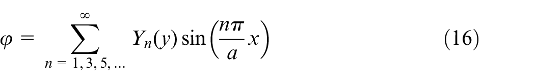
The right hand side of equation (14) can be expanded as a Fourier series between 0 and a so that
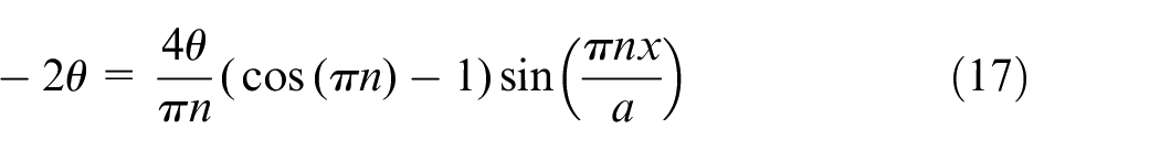
and since
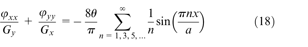
Substituting equations (16) into (18) and working out the differentials gives
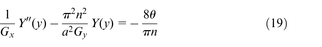
This is a second order Ordinary Differential Equation (ODE) which when solved for
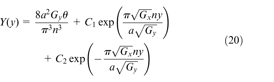
The constants
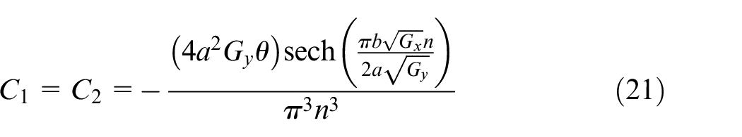
Plugging equations (21) into (20) then the result into equation (16) results in the final expression for the stress function
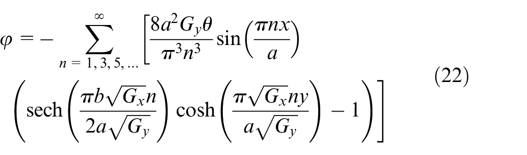
This is dependent on two shear moduli and the width and height of the wire, as wanted.
Torsional rigidity
The torsional rigidity is obtained from the following equation, 42
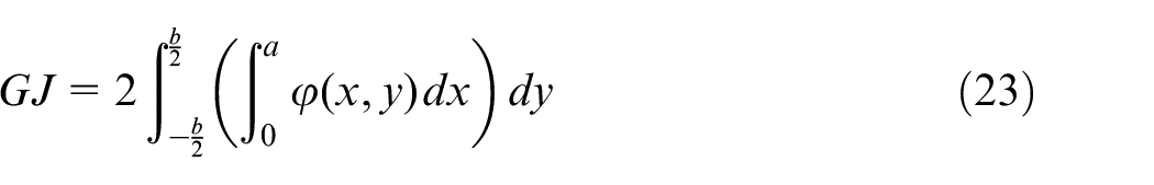
When combined with the fact that
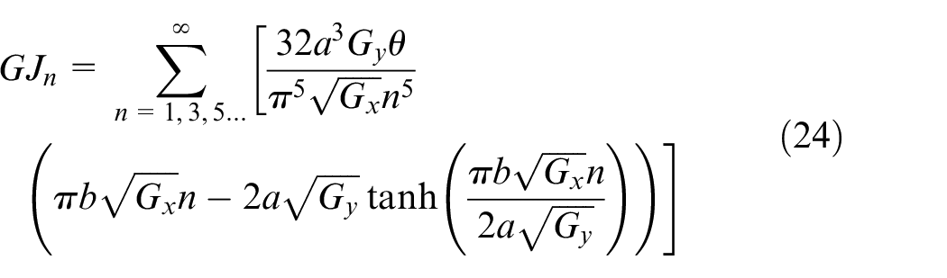
Here the values of
Derivation of the equation for k
Now that an expression for
Here
Plugging
then setting this equal to the energy stored by a spring, setting
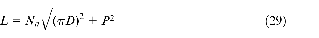
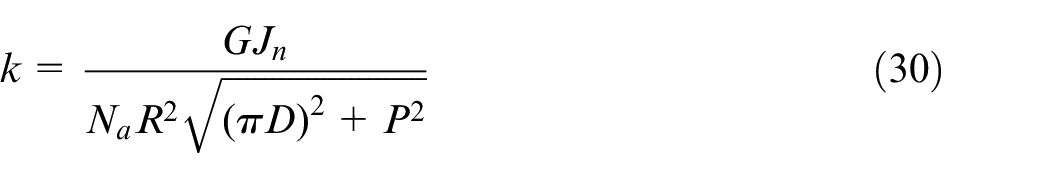
which is the length of a helix and where P is the pitch of the coils. Solving for k gives the final equation,
Shear moduli correction
As previously mentioned, close analysis shows that the cross-section of the spring’s wire is not entirely constant with the mono-directional in-fill. Figure 5(a) shows an idealized cross-section if the material is deposited in rectangles, which is unrealistic but adequate for demonstration. Figure 5(c) shows an approximation of what the spring looks like if it is uncoiled into a shaft and Figure 5(b) shows the cross-section taken on the right of Figure 5(c). At the bottom of the cross-section there is a continuous track, this is a consequence of the slicing where there are parts of each layer that are deposited radially to the axis of the spiral. There are in fact radial sections with different lengths so the cross-section will change throughout a single circle. It is theoretically possible to account for this changing cross-section but it overcomplicates the process of finding an analytical solution for the stress function so has not been considered here. As will be shown later, it was not necessary to take this into account.
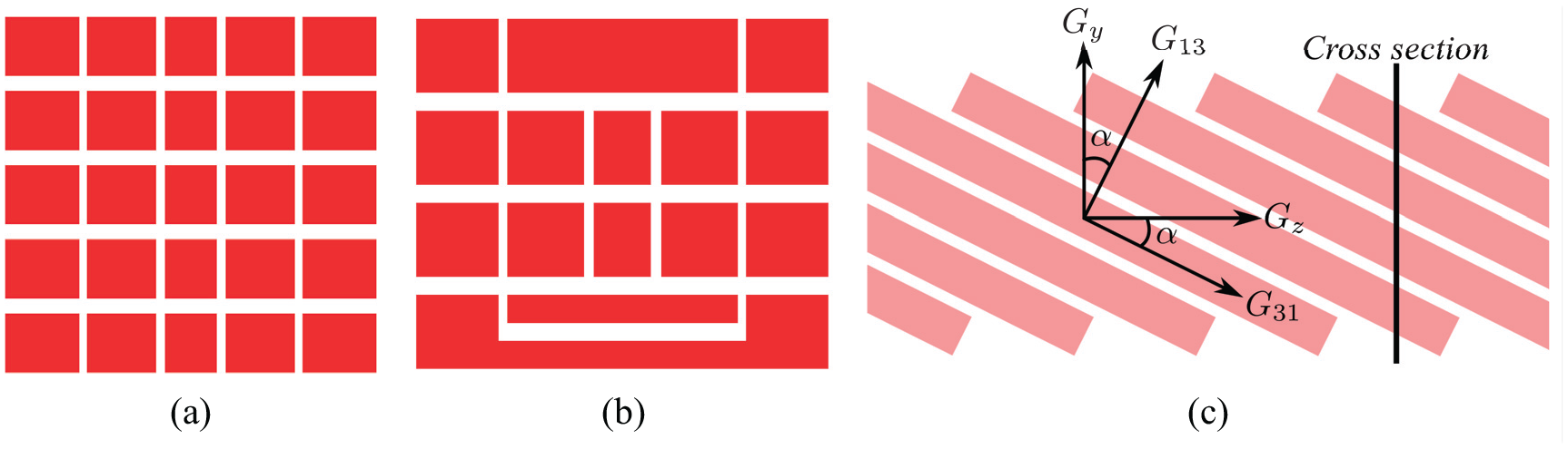
(a) Ideal spring wire cross-section, (b) more realistic cross-section and (c) side view of a more realistic uncoiled spring.
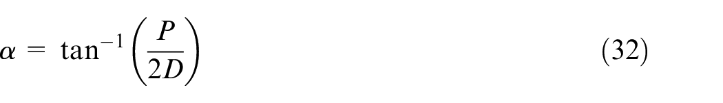
In Figure 5(c), the layers are not aligned to the z axis of Figure 3 and therefore it is possible that the shear moduli of the material need to be rotated onto the shear moduli of the shaft in order to give better predictions. Since the rotation takes place around the x axis in Figure 3,

where the angle
Two versions of equation (30) can therefore be written, one that includes the shear re-alignment so
Experimental data
As previously mentioned, PLA printed on FFF was the main material/printer combination used in this paper. The specific printer used was a Prusa i3 mk3 (www.prusa3d.com/original-prusa-i3-mk3). A Fortus 450 mc by Stratasys was used to print springs with ULTEM 9085.
Shear moduli of PLA
ASTM standard 5379
43
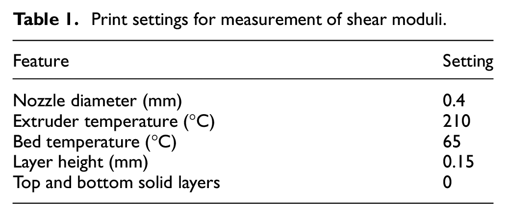
was used to measure the shear moduli and the printer settings can be found in Table 1. Ideally the number of outlines,
Print settings for measurement of shear moduli.
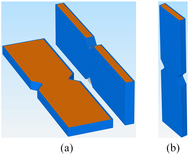
Shear coupons used for measuring the shear moduli of PLA and ULTEM 9085 in the slicing programme: (a)
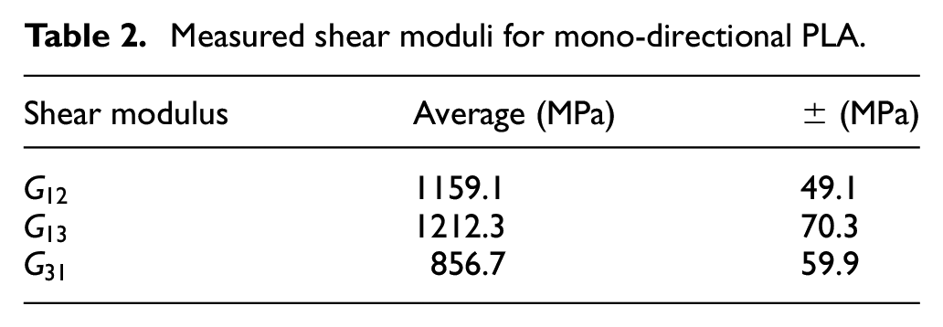
A Shimadzu Universal Testing Machine (UTM) with a 50 kN load cell was used to perform the testing at a constant head speed of 0.5 mm/min. The strain was measured using the Digital Image Correlation (DIC) software GOM Correlate (https://www.gom-correlate.com/) and the results are shown in Table 2. Each modulus is the average of the samples and the error is the standard deviation.
Measured shear moduli for mono-directional PLA.
Shear moduli of ULTEM 9085
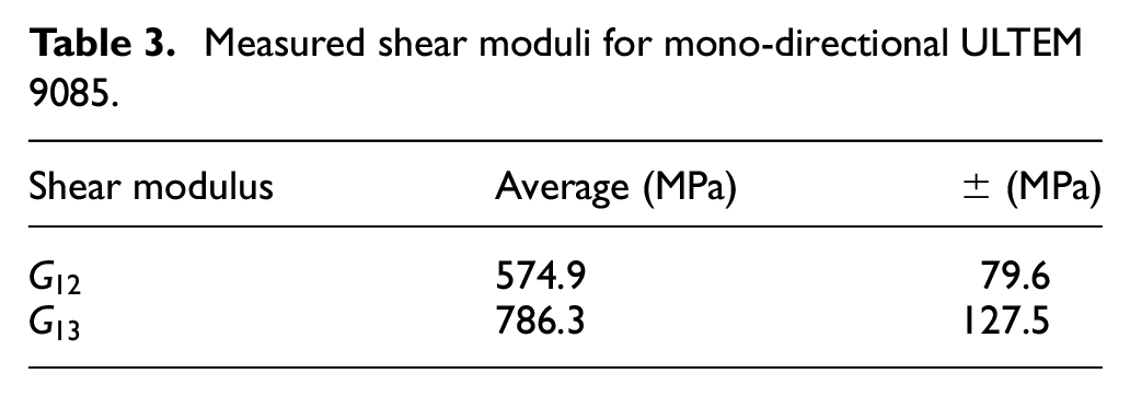
The shear moduli tabulated in Table 3 were measured using the same procedure and testing machine as for PLA.
Measured shear moduli for mono-directional ULTEM 9085.
Spring constants
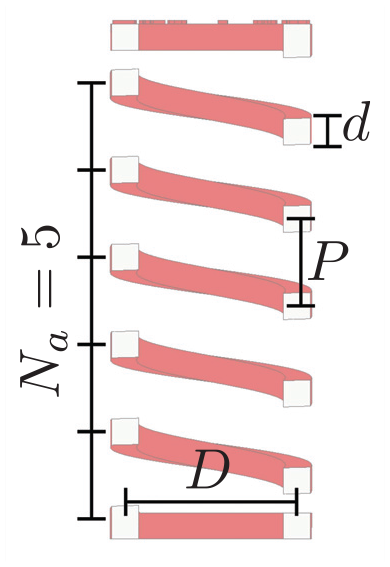
Next the spring constants of 27 PLA springs and 7 ULTEM springs were measured, one sample for every combination of parameters and all samples were compression springs. For PLA the printing parameters were the same as those shown in Table 1 with the only difference being the number of outlines which was set to 10. Three spring parameters were varied with three levels each: d, D and P, shown in Figure 1,
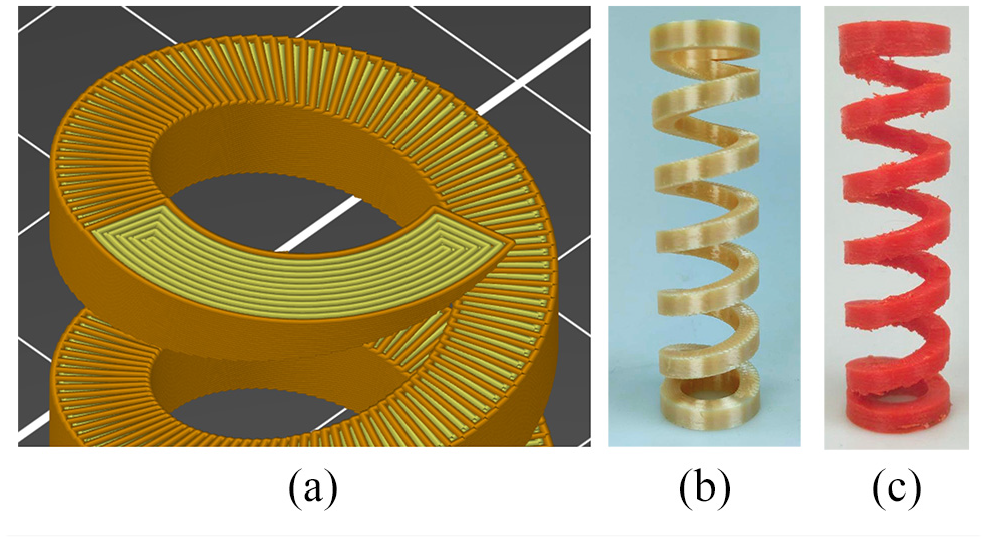
(a) Spring in slicing programme to show material deposition of mono-directional in-fill. Outlines are in orange and tracks for in-fill are in yellow, (b) d5D20P15 ULTEM 9085 spring and (c) d5D20P15 PLA spring.
The springs were compressed by 1 cm from rest over four cycles using a Shimadzu UTM with a 10 kN load cell at 80 mm/min. Figure 8 shows the force-displacement plots for four ULTEM 9085 springs, other springs displayed similar plots. The displacement was 1cm, so as to ensure that the springs did not deform during testing and remained elastic throughout the tests.
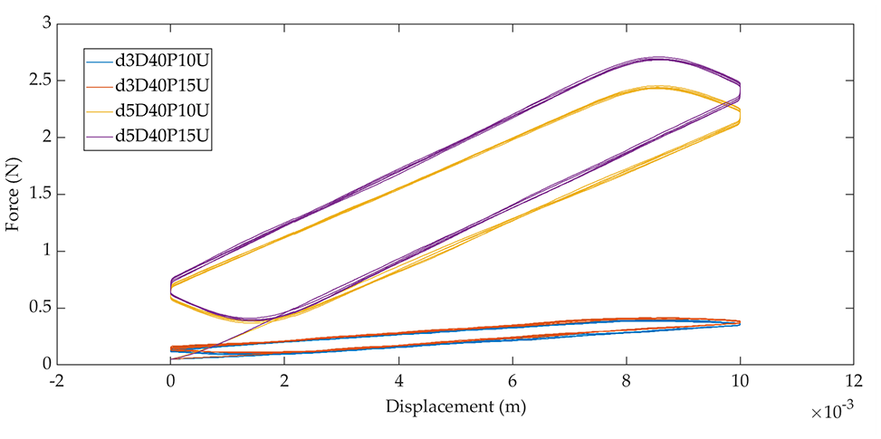
Example force-displacement plots: four ULTEM 9085 springs. Other springs displayed similar plots.
Comparison of experimental and calculated data
PLA
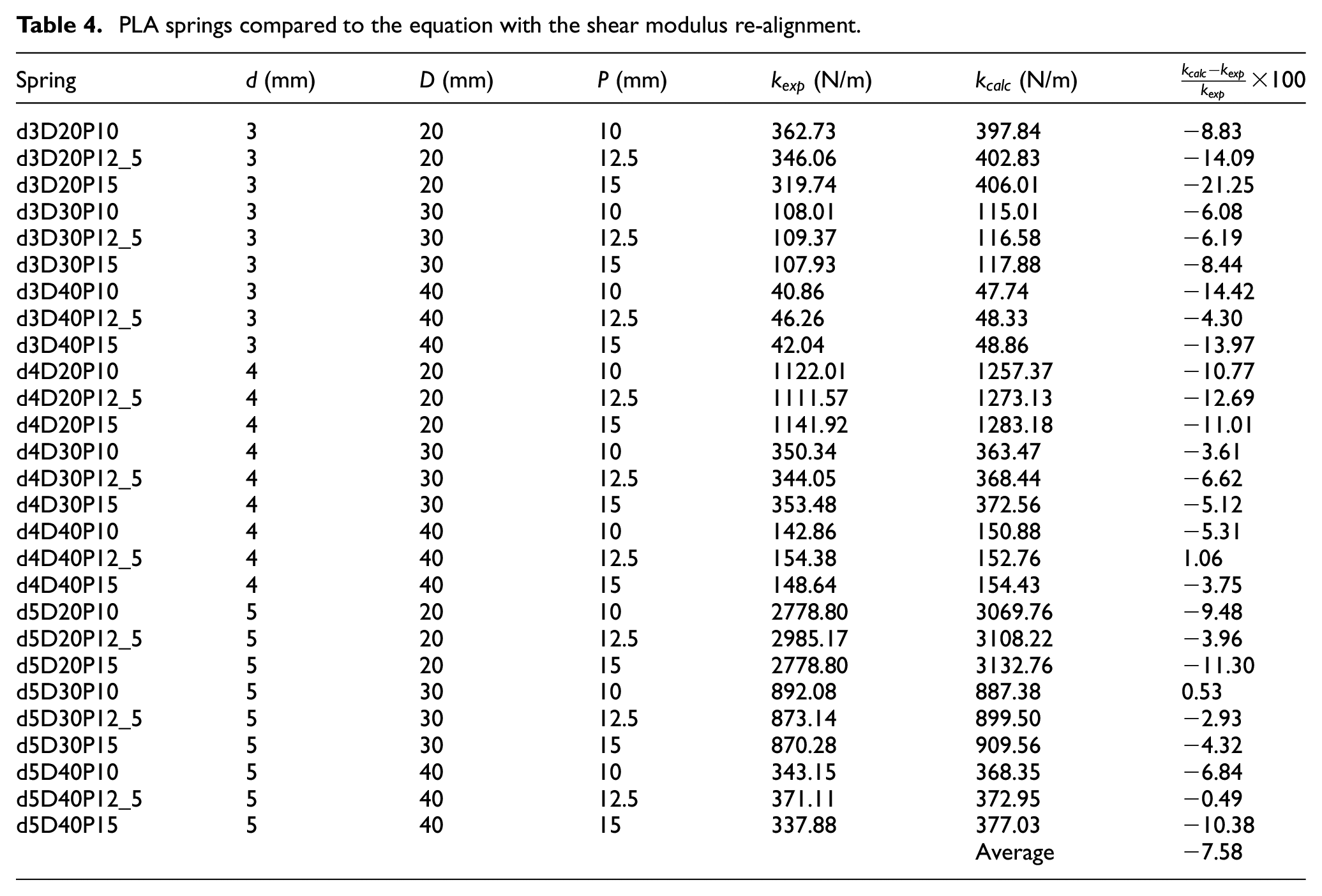
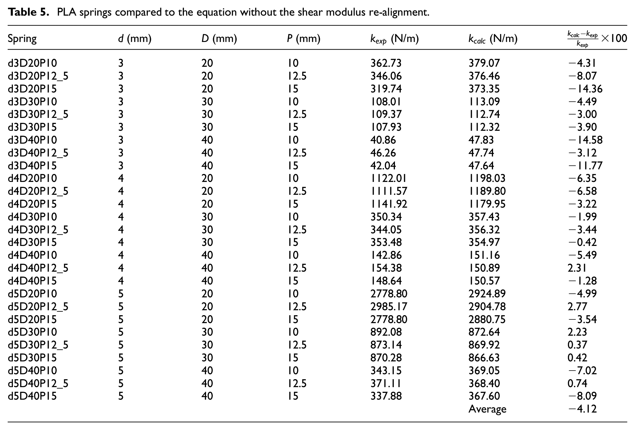
Tables 4 and 5 show the calculated spring stiffnesses with and without the shear re-alignment correction. Figure 9(a) and (b) show plots of the data from Tables 4 and 5. Figure 10 shows a box plot of the data from Tables 4 and 5. As can be seen in the tables, the difference between the experimental and calculated k s is small, the biggest being the d3D20P15 spring which is likely due to some imperfection during printing.
PLA springs compared to the equation with the shear modulus re-alignment.
PLA springs compared to the equation without the shear modulus re-alignment.
Plots of the measured and calculated k s: (a) with the shear re-alignment and (b) without the shear re-alignment.
Three very stiff d5D20P15 springs were also printed and tested, their spring constant being 25,009.50 N/M. Using the equation without the shear re-alignment gives a theoretical stiffness of 24,361 N/m, which is about 3% smaller than the experimental value. This result has not been included in Figure 9 because the value is 10 times greater than the next stiffest springs, thus making the bar chart difficult to read, but has been included in Table 5.
The variability in the experimental data is a consequence of two factors. First, the natural variability of the FFF process, which has been shown to produce parts which lack in dimensional and geometric precision due to the layer-by-layer fabrication of AM.44–46 Second, the printing process has not being optimized for every spring. The same print settings that were used to measure the shear moduli in were used for all PLA springs, which caused the springs to be manufactured with sub-optimal settings. This lead to more erratic mechanical responses, which was expected and compensated for by printing a large number of springs.
The last columns were added to Tables 4 and 5 to show the percentage difference between the calculated and measured k s. The average difference for the formula with the shear re-alignments is −7.58%, while without the shear re-alignment the average difference is only −4.12%. The smaller average difference favours the version of equation (30) without the shear re-alignment. The agreement of the experimental and calculated stiffness values, embodied by the average percentage difference, indicates that both versions of equation (30) are able to predict the spring constant.
A Wilcoxon Rank sum test for independent samples was performed on the two data sets for PLA, experimental and calculated, to determine if one of the two versions of equation (30) predicted values that were different from the experimental ones. The p-value when comparing the experimental and calculated stiffness values with shear re-alignment was 0.2919 at 5% significance level. For no shear re-alignment the p-value was 0.447 at 5% significance level.
Both sets of data failed to reject the null hypothesis that they are samples from continuous distributions with equal medians. Therefore, from this data it is not possible to determine which version of equation (30) gives better predictions, which is something that should be tested in future research.
The influence of the pitch on the spring constant seems negligible, whether looking at the experimental or calculated data. Upon closer inspection, the two versions of equation (30) predict two opposite behaviours, though: with the shear re-alignment k increases with the pitch, whereas without the shear re-alignment the stiffness drops as the pitch grows. This is another aspect that should be investigated in more detail in future research.
ULTEM 9085
A comparison between the experimental and calculated sets of k s for the ULTEM springs is tabulated in Table 6. The version of equation (30) without shear re-alignment was used. As can be seen, the percentage difference is comparable to those in Tables 4 and 5. The same Wilcoxon Rank sum test for independent samples was performed on this set of data. At a significance level of 5%, the p-value was 0.5887, which failed to reject the null hypothesis.
Comparison of calculated and experimental stiffness of ULTEM springs.
Conclusion
The design freedom afforded by 3D printing enables the manufacturing of parts that are difficult or impossible to make with conventional techniques. One way to take full advantage of this technology it to revisit old mechanisms and understand how they can be changed with 3D printing. Therefore, the objective of this paper was to model the stiffness of printed helical springs with rectangular wire cross-section. This necessitated four steps: (1) determining the mathematical problem; (2) derivation of the new equation; (3) gathering experimental data; and (4) comparison of theoretical and experimental values.
The proposed derivation method was first defined by equating the energy stored by a spring to that stored by a shaft under torsion. Assumptions made included that the material was going to be orthotropic, aligned in the direction of the helix, and that the spring wire had a rectangular cross-section. The new equation was derived by equating the energy stored by a beam under torsion to that of a spring. Two versions were created to account for the fact that one of the shear moduli may not be aligned along the coils as assumed. Finally, calculated and experimental spring constants were compared to verify the accuracy of the model. The material and printing method used were PLA with FFF and ULTEM 9085 with FDM. The first round of experiments was performed where the shear moduli of the printed materials were measured using ASTM standard 5379. Following this, various helical compression springs were printed and tested over two cycles at 80 mm/min with 1 cm displacement to measure their stiffness constants. The equations were found to closely predict the experimental results for both PLA and ULTEM 9085, allowing the design of springs without the need for extensive experimentation. The equation without the shear re-alignment has been found to produce satisfactory results using only two shear moduli. Measuring three shear moduli and using the equation with the shear re-alignment could give more accurate results, especially in the case of springs with higher pitch angles.
The proposed model is a novel orthotropic model to analytically calculate the stiffness of helical die springs. The model can be used for any anisotropic material for which the shear moduli can be measured, such as fibre reinforced composite filaments or transversely isotropic materials. Combined with metal AM techniques, the model allows the fast design and manufacturing of custom die springs without the need for winding that can lead to residual stresses.
This research is the basis for the development of models for novel spring designs, such as with varying wire cross-section or shapes other than rectangular and circular, such as triangular or rhombus. The extension of the model to non-linear, conical die springs is on-going and a model for torsion springs will also be developed in the future. Prototypes of spring designs such as with rectangular, hollow wires have been printed and will also be investigated in the future.
Footnotes
Appendix
Acknowledgements
A huge thank you to Simone Kager for all her help.
Author contributions
Enea Sacco: Data curation, Writing – original draft, Conceptualization, Methodology, Formal analysis, Software, Validation. Seung Ki Moon: Conceptualization, Supervision, Writing – review & editing, Funding acquisition.
Declaration of conflicting interests
The author(s) declared no potential conflicts of interest with respect to the research, authorship, and/or publication of this article.
Funding
The author(s) disclosed receipt of the following financial support for the research, authorship, and/or publication of this article: This research was supported by the Singapore Centre for 3D printing (SC3DP), the National Research Foundation, Prime Minister’s Office, Singapore under its Medium-Sized Centre funding scheme, and National Additive Manufacturing Innovation Cluster.